HONDA INTEGRA 1998 4.G Workshop Manual
Manufacturer: HONDA, Model Year: 1998, Model line: INTEGRA, Model: HONDA INTEGRA 1998 4.GPages: 1681, PDF Size: 54.22 MB
Page 831 of 1681
r
Doors
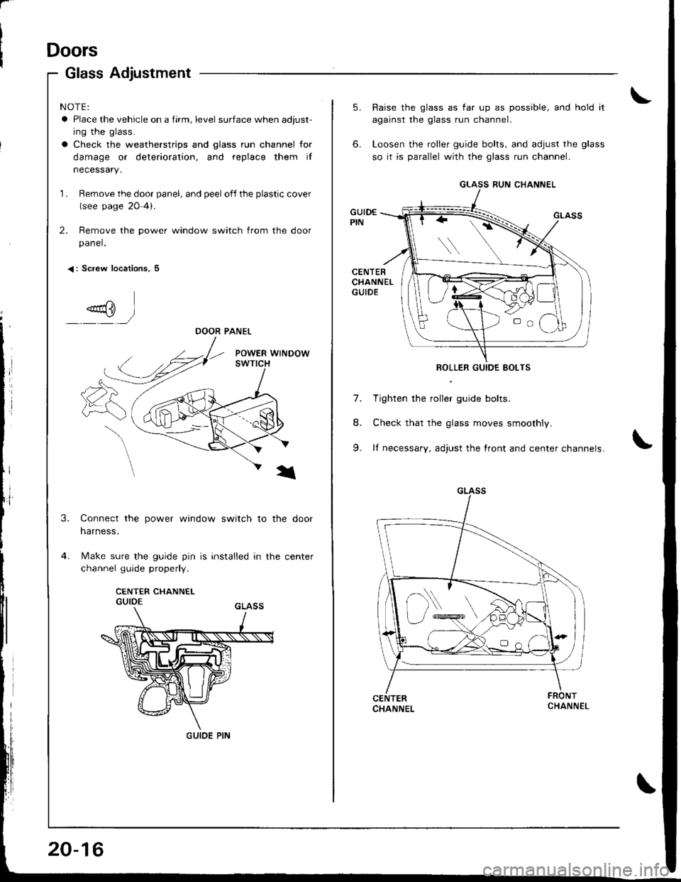
Glass Adjustment
< : Screw locations, 5
"od} l-,/
NOTE:
a Place the vehicle on a firm, level surface when adjust-
ing the glass.
a Check the weatherstrips and glass run channel for
damage or deterioration, and replace them iI
necessarY.
1 . Remove the door panel, and peel off the plastic cover(see page 20 4).
2. Remove the power window switch from the door
panel.
DOOR PANEL
3.Connect the power window switch to the door
harness.
Make sure the guide pin is installed in the center
channel guide properly.
CENTER CHANNELGUIDE
GUIDE PIN
20-16
5. Raise the glass as iar up as possible, and hold it
against the glass run channel.
6. Loosen the roller guide bolts, and adjust the glass
so it is parallel with the glass run channel.
GUID€PIN
CENTEBCHANNELGUIDE
ROLLER GUIDE BOLTS
7. Tighten the roller guide bolts.
8. Check that the glass moves smoothly.
9. It necessary, adjust the lront and center channels.
CHANNEL
GLASS RUN CHANNEL
D\
Page 832 of 1681
'to.
11.
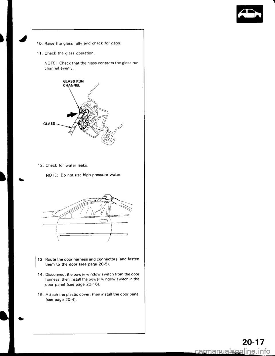
Raise the glass fully and check Ior gaps.
Check the glass operation.
NOTEi Check that the glass contacts the glass run
channel evenly.
12. Check for water leaks.
NOTE: Do not use high-pressure water.
13. Route the door harness and connectors, and fasten
them to the door (see page 2O-5).
Disconnect the power window switch lrom the door
harness, then installthe power window switch in the
door panel (see page 20 l6).
Attach the plastic cover, then install the door panel
(see page 2O-4).
14.
20-17
Page 833 of 1681
Doors
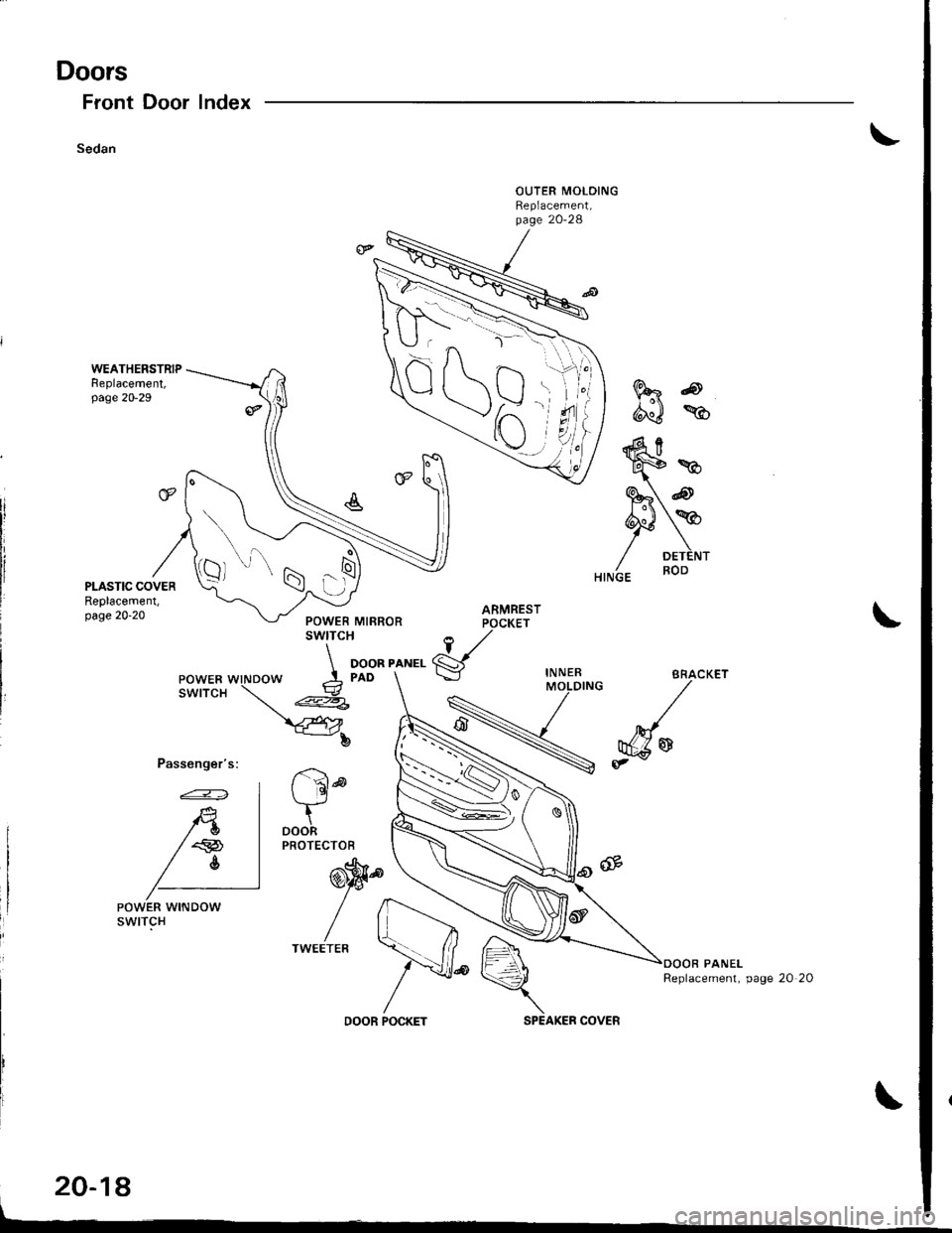
Front Door
Sedan
Index
Passenger's:
FRo
d"J %
ARMRESTPOCKET
1,/
gIN NERMOLDING
r '6ld
tDOORPROTECTOB
@'9.
//
/lTWEETEB
20-18
POWER WINDOWswtTcH
Replacement, page 20 20
DOOR POCKETSPEAKER COVER
\-^\
\
Qt
-N'a x^ l---r z
)r\
s'ti
7t"i
.1\N
J.-ra 1--
o t
:6
w*
S" @
PY/ DETENT
Page 834 of 1681
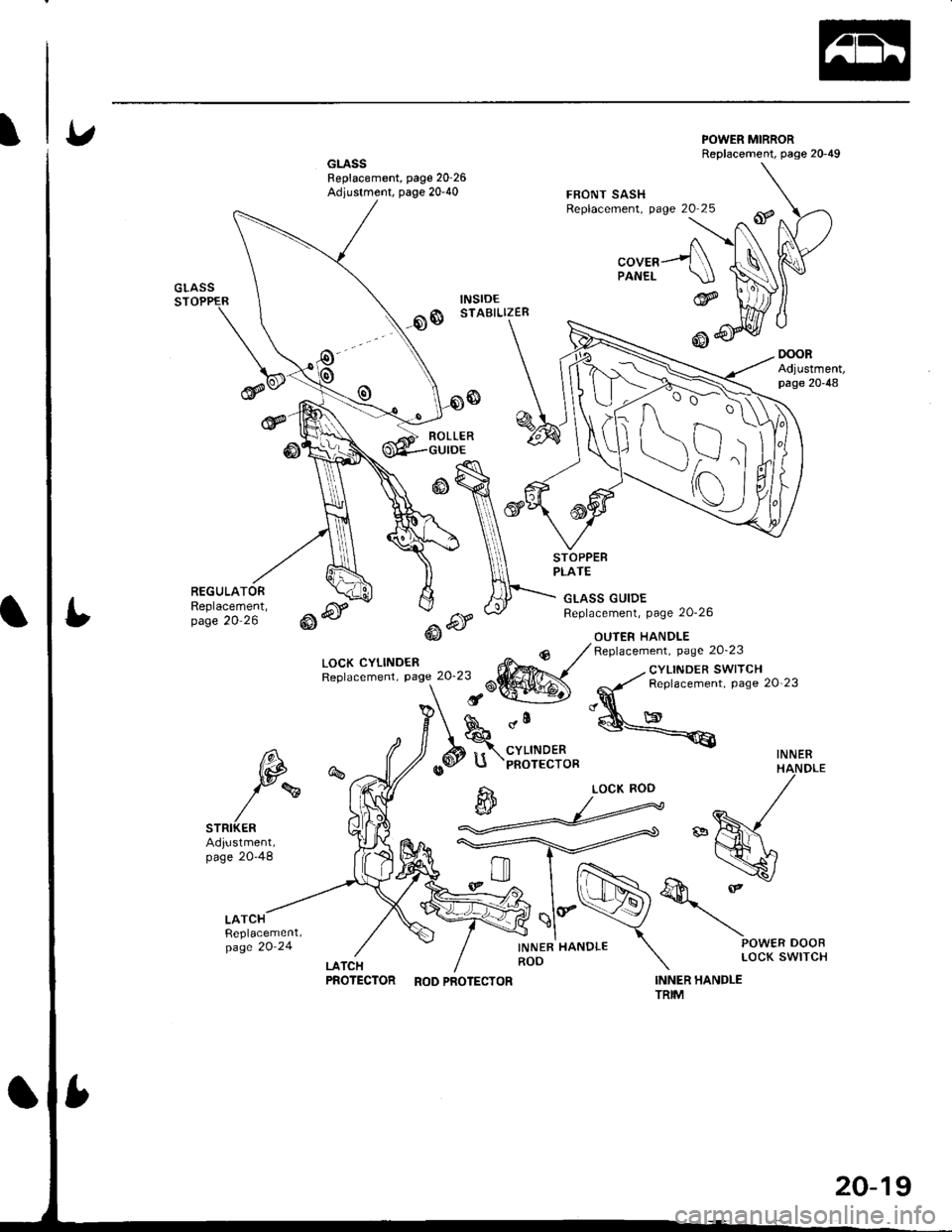
GLASSFeplacement, page 20'26Adjustment, page 20-40
POWER MIRRORReplacement, page 20-49
oooRAdjustment,page 20-48
FBONT SASHReplacement, page 20 25
"oura---f\PANEL \.IJGLASSSTOPPER
@
REGULATORReplacement,page 20 26
ROLLER
LOCK CYLINDENReplacement, Page 20'23
GLASS GUIDEReplacement, page 20-26
OUIER HANDLE
STOPPEBPLATE
@6r-.6f@J
dll
CYLINDERPNOTECTOR
INNER HANDLEROD
Replacement. page 20'23
INNER HANDLETRIM
_. cYLINDER SWITCH
-,y' Replacement. page 20 23
"q
@<€
INNER6\,
tp
)rw
STRIKERAdiustment,page 20-48
%
LATCHReplacement,page 20'24
@
d
LOCK ROD
PROTECTOR RoDPRoTEcToR
20-19
Page 835 of 1681
Doors
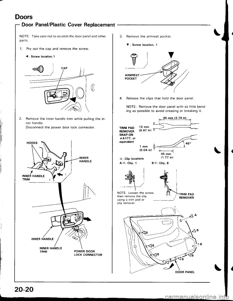
Door Panel/Plastic Cover Replacement
NOTEr Take care not to scratch the door panel and other
parts.
1. Pry out the cap and remove the screw.
< : Screw location,l
I
t'li
I
Remove the inner handle trim while pulling the in-
ner handle.
Disconnect the power door lock connector.
INNER
20-20
3.Remove the armrest pockel.
V: Screw location, 1
TRIM PADREMOVERSNAP-ON#4177, olequivalent
12 mm{0.47 inl T-
'I mm !-'-{0.04 in} I +45 rnm
<: Clip locations
A<: Clip, 1
11.77 inl
B<: Clip, 8
NOTE: Loosen the screw,then remove the clipusing a trim pad orclip remover.
AI
Yv)
ARMRESTPOCKET
4. Release the clips that hold the door panel.
NOTE: Remove the door panel with as little bend-
ing as possible to avoid creasing or breaking it.
95 mm (3.74 in)
Page 836 of 1681
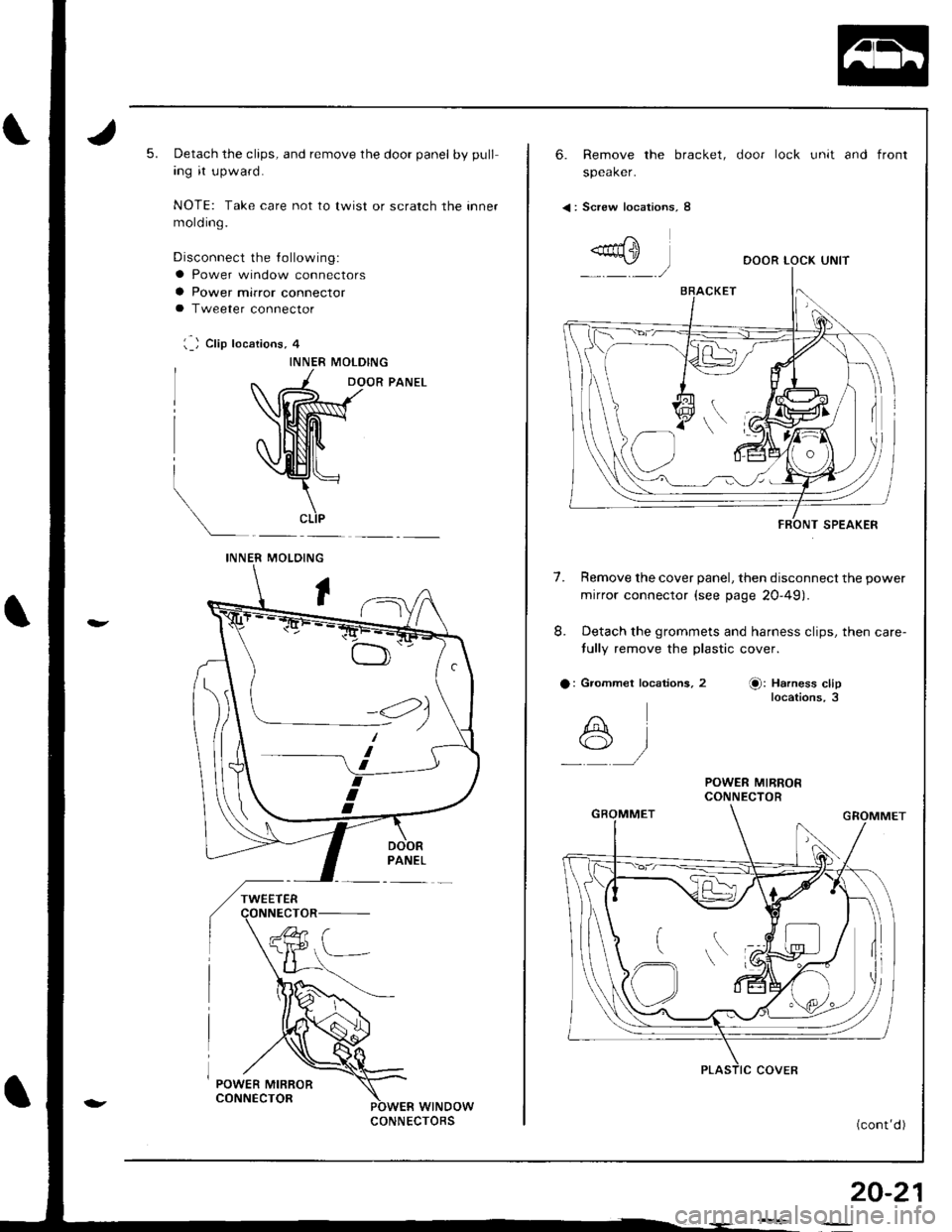
5.Detach the clips, and remove the door panel by pull
ing it upward.
NOTE: Take care not to lwist or scratch the inner
mold ing.
Disconnect the lollowing:
a Power window connectors
a Power mirror connectora Tweeter connector
l._) Clip locations, 4
INNER MOLDING
DOOR PANEL
t
INNERMOLOING
wtNDowCONNECTORS
< : Screw locations, 8
FBONT SPEAKER
6. Remove the bracket, door lock unit and front
speaker.
DOOR LOCK UNIT
7.Remove the cover panel, then disconnect the power
mirror connector (see page 20-49)
Detach the grommets and harness clips, then care-
tully remove the plastic cover.
a: Grommet localions, 2O: Harness cliplocations,3
R
*A-1
POWER MIRRORCONNECTOR
(cont'd )
20-21
::
Page 837 of 1681
Doors
Door Panel/Plastic Cover Replacement (cont'd)
20-22
L--
\
\
\
'10.
uoor ranel/rlasrlc uover heplacen
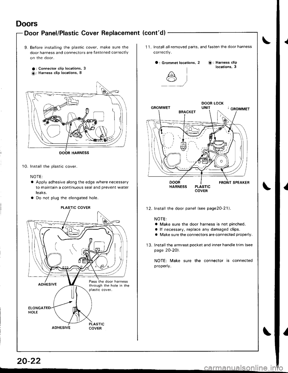
L Be{ore installing the plastic cover, make sure the
door harness and connectors are lastened correctly
on the door.
a: Connector clip locations, 3
O: Harness clip locations, 8
Install the plastic cover.
NOTE:
a Apply adhesive along the edge where necessary
to maintain a continuous seal and prevent water
reaKs.
a Do not plug the elongated hole.
ADHESIVECOVER
PLASTIC COVER
Pass the door harnessthrough the hole in theplastrc cover,
1 '1. Install all removed parts, and tasten the door harness
correctly.
O : Grommet locations,
A*,/
2 Or Harness cliplocations, 3
1)
GROMMET
HARNESS PLASTICCOVER
Install the door panel (see page2o-21).
NOTE:
a Make sure the door harness is not pinched.
a lf necessary, replace any damaged clips.
a Make sure the connectors are connected properly.
Install the armrest pocket and inner handle trim (see
page 2O-2Ol.
NOTE: N4ake sure the connector is connected
properly.
{
{
I
Page 838 of 1681
Outer Handle Replacement
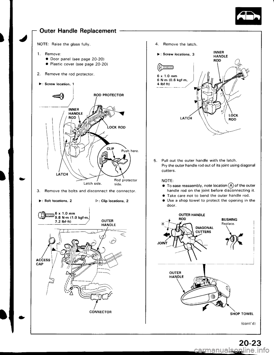
NOTEr Raise the glass jully.
'1. Removel
a Door panel {see page 20-20)
a Plastic cover (see page 20 20)
2. Remove the rod protector.
>: Screw location, 1
-
-
Latch side. side.
3. Remove the bolts and disconnect the connector.
>: Bolt locatiohs, 2
I
f$iT'r.*' 6 x 1.0 mm I\4/l* 9.4 N.m {1.0 ksf.m,i
ryty!! J
>: Clip locations, 2
20-23
- -<--
INNERHANDLE
CONNECTOR
4. Remove the latch.
>: Screw locations, 3
6 x '1.0 mm6 N.m {0.6 kgl4 tbf.tr)
5.Pull out the outer handle with the latch.
Pry the outer handle rod out ol its joint using diagonal
culters.
NOTE:
a To ease reassembly, note location @ of the outer
handle rod on the joint before disconnecting it.
a Take care not to bend the outer handle rod.
a Use a shop towel to protect the opening in the
door.
BUSHINGReplace.
h
SHOP TOWEL
{cont'd )
Page 839 of 1681
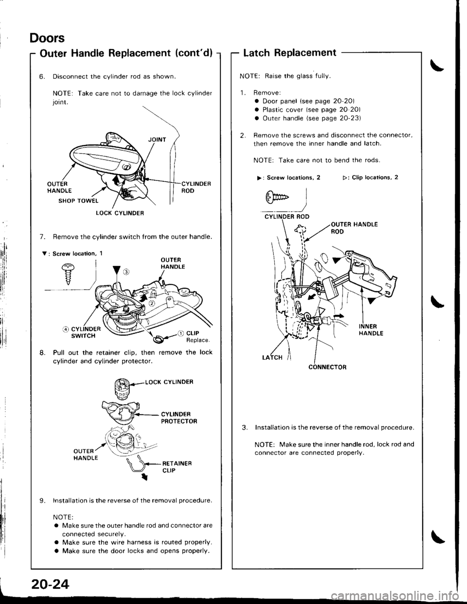
Doors
Outer HandleReplacement (cont'd)
irl
lii
,l
r
LatchReplacement
NOTE: Raise the glass fully.
1. Remove:
a Door panel (see page 20 20)
a Plastic cover (see page 20 20)
a Outer handle (see page 20'23)
2- Remove the screws and disconnect the connector,
then remove the inner handle and latch.
NOTEr Take care not to bend the rods.
> | Screw locations, 2
6bD l
:)CYLINDER ROO
>: Clip locaiions, 2
3.Installation is the reverse of the removal procedure.
NOTE: Make sure the inner handle rod, lock rod and
connector are connected properly.
6.
7.
v:
Disconnect the cylinder rod as shown.
NOTE: Take care not to damage the lock cylinder
Jornt.
OUTERHANDLE
SHOP TOWEL
Remove the cylindef switch from the outer handle.
Pull out the retainer clip, then remove the lock
cylinder and cylinder protector.
8.
L
g--.-.o"*
cYLTNDER
lnstallation is the reverse of the removal procedure.
NOTE:
a Make sure the outer handle rod and connector are
connected securely.
a Make sure the wire harness is routed properly.
a Make sure the door locks and opens properly.
LOCK CYLINOEB
Page 840 of 1681
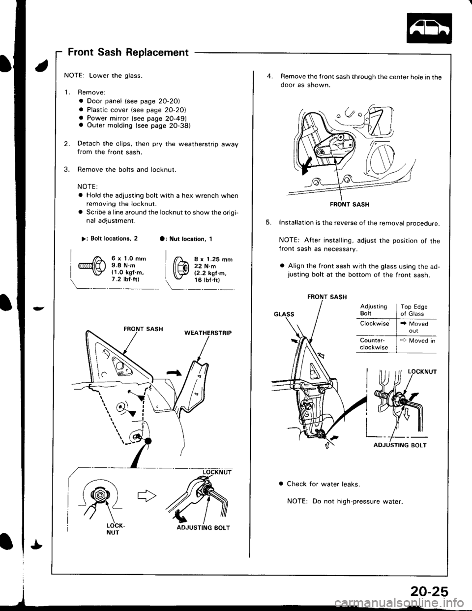
Front Sash Replacement
NOTE: Lower the glass.
1. Removel
. Door panel (see page 20-20)
a Plastic cover (see page 20,20)a Power mirror (see page 20-491a Outer molding (see page 20-381
Detach the clips, then pry the weatherstrip awayfrom the front sash.
Remove the bolts and locknut.
NOTE:
a Hold the adjusting bolt with a hex wrench when
removing the locknut.
a Scribe a line around the locknut to show the origi-
nal adjustment.
>: Bolt locations, 2
| ,f> 6x 1.0 mm
r @lE ) s.8 N.m
| \:Z 11.0 kel.m,
7.2 tbr.ril\-__ - _ -_
a: llut location. 'l
I lX "x r.2s mm
[{,W i,1i;T'-.'\:. ru_'otn'l_
IN
ADJUSTING BOLT
Remove the front sash through the center hole in the
ooor as snown.
FRONT SASH
5. Installation is the reverse of the removal procedure.
NOTE: After installing, adjust the position ol thefront sash as necessary.
a Align the tront sash with the glass using the ad-justing bolt at the bottom of the front sash.
a Check for water leaks.
NOTE: Do not high-pressure water.