INFINITI QX56 2007 Factory Service Manual
Manufacturer: INFINITI, Model Year: 2007, Model line: QX56, Model: INFINITI QX56 2007Pages: 3061, PDF Size: 64.56 MB
Page 1091 of 3061

EC-8
DTC Confirmation Procedure ................................567
Wiring Diagram ......................................................569
Diagnosis Procedure .............................................570
Component Inspection ...........................................572
Removal and Installation .......................................573
DTC P2135 TP SENSOR .................................574
Component Description .........................................574
CONSULT-II Reference Value in Data Monitor
Mode ......................................................................
574
On Board Diagnosis Logic .....................................574
DTC Confirmation Procedure ................................574
Wiring Diagram ......................................................576
Diagnosis Procedure .............................................577
Component Inspection ...........................................579
Removal and Installation .......................................580
DTC P2138 APP SENSOR ..............................581
Component Description .........................................581
CONSULT-II Reference Value in Data Monitor
Mode ......................................................................
581
On Board Diagnosis Logic .....................................581
DTC Confirmation Procedure ................................582
Wiring Diagram ......................................................583
Diagnosis Procedure .............................................584
Component Inspection ...........................................587
Removal and Installation .......................................587
DTC P2A00, P2A03 A/F SENSOR 1 ...............588
Component Description .........................................588
CONSULT-II Reference Value in Data Monitor
Mode ......................................................................
588
On Board Diagnosis Logic .....................................588
DTC Confirmation Procedure ................................588
Wiring Diagram ......................................................590
Diagnosis Procedure .............................................593
Removal and Installation .......................................596
ASCD BRAKE SWITCH ..................................597
Component Description .........................................597
CONSULT-II Reference Value in Data Monitor
Mode ......................................................................
597
Wiring Diagram ......................................................598
Diagnosis Procedure .............................................599
Component Inspection ...........................................602
ASCD INDICATOR ..........................................603
Component Description .........................................603
CONSULT-II Reference Value in Data Monitor
Mode ......................................................................
603
Wiring Diagram ......................................................604
Diagnosis Procedure .............................................604
ELECTRICAL LOAD SIGNAL .........................606
Description .............................................................606
CONSULT-II Reference Value in Data Monitor
Mode ......................................................................
606
Diagnosis Procedure .............................................606
FUEL INJECTOR ..............................................608
Component Description ........................................608
CONSULT-II Reference Value in Data Monitor
Mode .....................................................................
608
Wiring Diagram .....................................................609
Diagnosis Procedure .............................................610
Component Inspection ..........................................612
Removal and Installation .......................................612
FUEL PUMP .....................................................613
Description ............................................................613
CONSULT-II Reference Value in Data Monitor
Mode .....................................................................
613
Wiring Diagram .....................................................614
Diagnosis Procedure .............................................615
Component Inspection ..........................................617
Removal and Installation .......................................618
ICC BRAKE SWITCH .......................................619
Component Description ........................................619
CONSULT-II Reference Value in Data Monitor
Mode .....................................................................
619
Wiring Diagram .....................................................620
Diagnosis Procedure .............................................621
Component Inspection ..........................................624
IGNITION SIGNAL ............................................626
Component Description ........................................626
Wiring Diagram .....................................................627
Diagnosis Procedure .............................................632
Component Inspection ..........................................635
Removal and Installation .......................................637
REFRIGERANT PRESSURE SENSOR ...........638
Component Description ........................................638
Wiring Diagram .....................................................639
Diagnosis Procedure .............................................640
Removal and Installation .......................................642
MIL AND DATA LINK CONNECTOR ...............643
Wiring Diagram .....................................................643
SERVICE DATA AND SPECIFICATIONS
(SDS) ................................................................
645
Fuel Pressure ........................................................645
Idle Speed and Ignition Timing .............................645
Calculated Load Value ..........................................645
Mass Air Flow Sensor ...........................................645
Intake Air Temperature Sensor .............................645
Engine Coolant Temperature Sensor ...................645
A/F Sensor 1 Heater .............................................645
Heated Oxygen sensor 2 Heater ..........................645
Crankshaft Position Sensor (POS) .......................646
Camshaft Position Sensor (PHASE) .....................646
Throttle Control Motor ...........................................646
Fuel Injector ..........................................................646
Fuel Pump .............................................................646
Page 1092 of 3061

INDEX FOR DTC
EC-9
< SERVICE INFORMATION >
C
D
E
F
G
H
I
J
K
L
MA
EC
N
P O
SERVICE INFORMATION
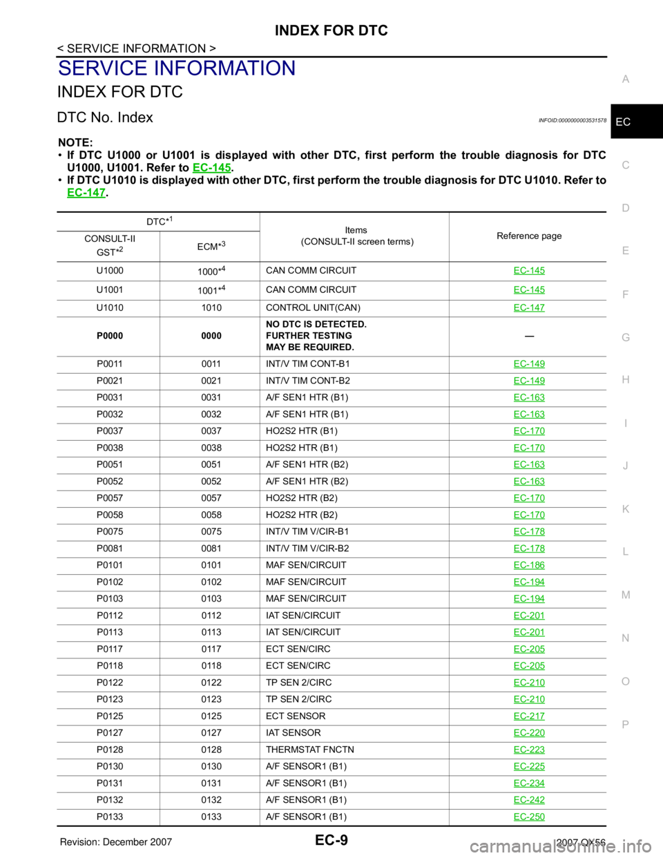
INDEX FOR DTC
DTC No. IndexINFOID:0000000003531578
NOTE:
•If DTC U1000 or U1001 is displayed with other DTC, first perform the trouble diagnosis for DTC
U1000, U1001. Refer to EC-145
.
•If DTC U1010 is displayed with other DTC, first perform the trouble diagnosis for DTC U1010. Refer to
EC-147
.
DTC*1
Items
(CONSULT-II screen terms)Reference page
CONSULT-II
GST*
2ECM*3
U1000
1000*4CAN COMM CIRCUITEC-145
U1001
1001*4CAN COMM CIRCUITEC-145
U1010 1010 CONTROL UNIT(CAN)EC-147
P0000 0000NO DTC IS DETECTED.
FURTHER TESTING
MAY BE REQUIRED.—
P0011 0011 INT/V TIM CONT-B1EC-149
P0021 0021 INT/V TIM CONT-B2EC-149
P0031 0031 A/F SEN1 HTR (B1)EC-163
P0032 0032 A/F SEN1 HTR (B1)EC-163
P0037 0037 HO2S2 HTR (B1)EC-170
P0038 0038 HO2S2 HTR (B1)EC-170
P0051 0051 A/F SEN1 HTR (B2)EC-163
P0052 0052 A/F SEN1 HTR (B2)EC-163
P0057 0057 HO2S2 HTR (B2)EC-170
P0058 0058 HO2S2 HTR (B2)EC-170
P0075 0075 INT/V TIM V/CIR-B1EC-178
P0081 0081 INT/V TIM V/CIR-B2EC-178
P0101 0101 MAF SEN/CIRCUITEC-186
P0102 0102 MAF SEN/CIRCUITEC-194
P0103 0103 MAF SEN/CIRCUITEC-194
P0112 0112 IAT SEN/CIRCUITEC-201
P0113 0113 IAT SEN/CIRCUITEC-201
P0117 0117 ECT SEN/CIRCEC-205
P0118 0118 ECT SEN/CIRCEC-205
P0122 0122 TP SEN 2/CIRCEC-210
P0123 0123 TP SEN 2/CIRCEC-210
P0125 0125 ECT SENSOREC-217
P0127 0127 IAT SENSOREC-220
P0128 0128 THERMSTAT FNCTNEC-223
P0130 0130 A/F SENSOR1 (B1)EC-225
P0131 0131 A/F SENSOR1 (B1)EC-234
P0132 0132 A/F SENSOR1 (B1)EC-242
P0133 0133 A/F SENSOR1 (B1)EC-250
Page 1093 of 3061

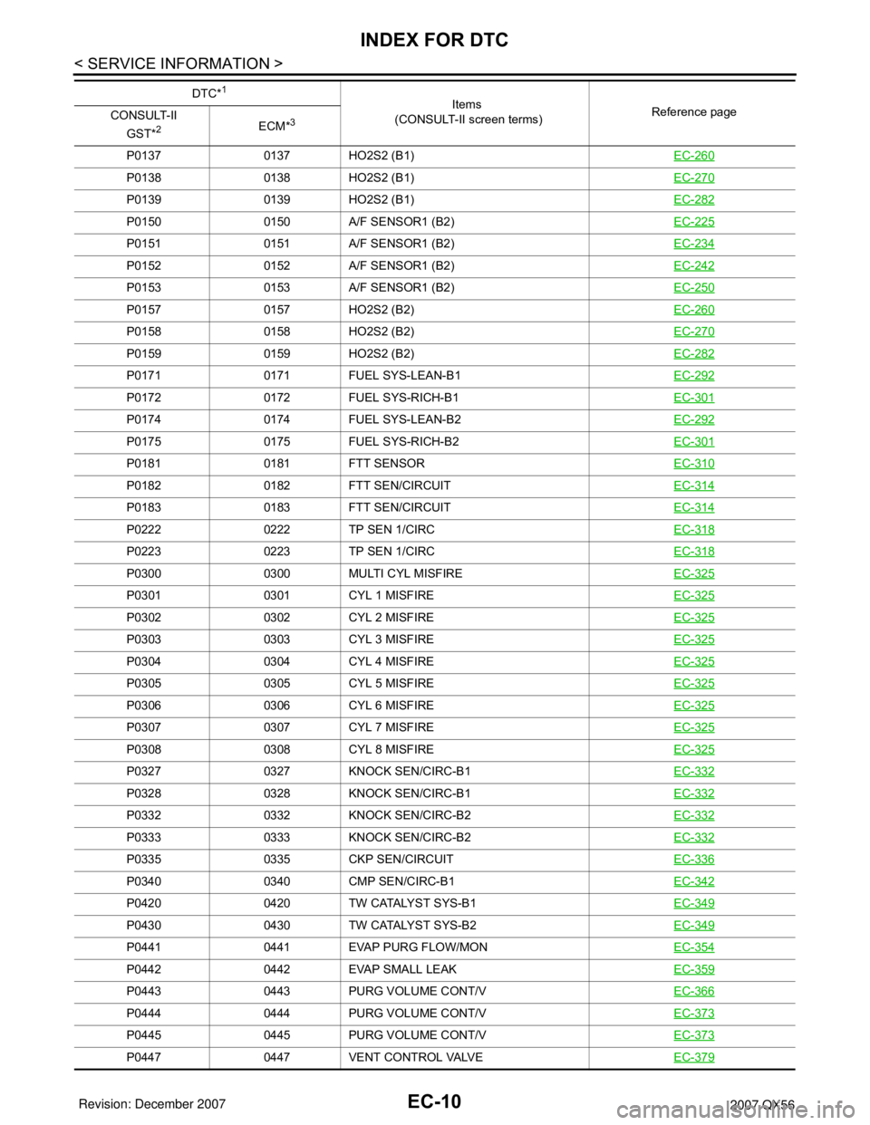
EC-10
< SERVICE INFORMATION >
INDEX FOR DTC
P0137 0137 HO2S2 (B1)EC-260
P0138 0138 HO2S2 (B1)EC-270
P0139 0139 HO2S2 (B1)EC-282
P0150 0150 A/F SENSOR1 (B2)EC-225
P0151 0151 A/F SENSOR1 (B2)EC-234
P0152 0152 A/F SENSOR1 (B2)EC-242
P0153 0153 A/F SENSOR1 (B2)EC-250
P0157 0157 HO2S2 (B2)EC-260
P0158 0158 HO2S2 (B2)EC-270
P0159 0159 HO2S2 (B2)EC-282
P0171 0171 FUEL SYS-LEAN-B1EC-292
P0172 0172 FUEL SYS-RICH-B1EC-301
P0174 0174 FUEL SYS-LEAN-B2EC-292
P0175 0175 FUEL SYS-RICH-B2EC-301
P0181 0181 FTT SENSOREC-310
P0182 0182 FTT SEN/CIRCUITEC-314
P0183 0183 FTT SEN/CIRCUITEC-314
P0222 0222 TP SEN 1/CIRCEC-318
P0223 0223 TP SEN 1/CIRCEC-318
P0300 0300 MULTI CYL MISFIREEC-325
P0301 0301 CYL 1 MISFIREEC-325
P0302 0302 CYL 2 MISFIREEC-325
P0303 0303 CYL 3 MISFIREEC-325
P0304 0304 CYL 4 MISFIREEC-325
P0305 0305 CYL 5 MISFIREEC-325
P0306 0306 CYL 6 MISFIREEC-325
P0307 0307 CYL 7 MISFIREEC-325
P0308 0308 CYL 8 MISFIREEC-325
P0327 0327 KNOCK SEN/CIRC-B1EC-332
P0328 0328 KNOCK SEN/CIRC-B1EC-332
P0332 0332 KNOCK SEN/CIRC-B2EC-332
P0333 0333 KNOCK SEN/CIRC-B2EC-332
P0335 0335 CKP SEN/CIRCUITEC-336
P0340 0340 CMP SEN/CIRC-B1EC-342
P0420 0420 TW CATALYST SYS-B1EC-349
P0430 0430 TW CATALYST SYS-B2EC-349
P0441 0441 EVAP PURG FLOW/MONEC-354
P0442 0442 EVAP SMALL LEAKEC-359
P0443 0443 PURG VOLUME CONT/VEC-366
P0444 0444 PURG VOLUME CONT/VEC-373
P0445 0445 PURG VOLUME CONT/VEC-373
P0447 0447 VENT CONTROL VALVEEC-379
DTC*1
Items
(CONSULT-II screen terms)Reference page
CONSULT-II
GST*
2ECM*3
Page 1094 of 3061

INDEX FOR DTC
EC-11
< SERVICE INFORMATION >
C
D
E
F
G
H
I
J
K
L
MA
EC
N
P OP0448 0448 VENT CONTROL VALVEEC-386
P0451 0451 EVAP SYS PRES SENEC-392
P0452 0452 EVAP SYS PRES SENEC-395
P0453 0453 EVAP SYS PRES SENEC-401
P0455 0455 EVAP GROSS LEAKEC-408
P0456 0456 EVAP VERY SML LEAKEC-415
P0460 0460 FUEL LEV SEN SLOSHEC-423
P0461 0461 FUEL LEVEL SENSOREC-425
P0462 0462 FUEL LEVL SEN/CIRCEC-427
P0463 0463 FUEL LEVL SEN/CIRCEC-427
P0500 0500
VEH SPEED SEN/CIRC*5EC-429
P0506 0506 ISC SYSTEMEC-431
P0507 0507 ISC SYSTEMEC-433
P0550 0550 PW ST P SEN/CIRCEC-435
P0603 0603 ECM BACK UP/CIRCUITEC-440
P0605 0605 ECMEC-444
P0643 0643 SENSOR POWER/CIRCEC-447
P0700 0700 TCMAT- 9 8
P0705 0705 PNP SW/CIRCAT- 9 9
P0710 0710 ATF TEMP SEN/CIRCAT- 11 9
P0720 0720
VEH SPD SEN/CIR AT*5AT- 1 0 5
P0740 0740 TCC SOLENOID/CIRCAT- 111
P0744 0744 A/T TCC S/V FNCTNAT- 11 3
P0745 0745 L/PRESS SOL/CIRCAT- 11 5
P0850 0850 P-N POS SW/CIRCUITEC-452
P1140 1140 INTK TIM S/CIRC-B1EC-457
P1145 1145 INTK TIM S/CIRC-B2EC-457
P1148 1148 CLOSED LOOP-B1EC-466
P1168 1168 CLOSED LOOP-B2EC-466
P1211 1211 TCS C/U FUNCTNEC-467
P1212 1212 TCS/CIRCEC-468
P1217 1217 ENG OVER TEMPEC-469
P1225 1225 CTP LEARNINGEC-477
P1226 1226 CTP LEARNINGEC-479
P1421 1421 COLD START CONTROLEC-481
P1550 1550 BAT CURRENT SENSOREC-483
P1551 1551 BAT CURRENT SENSOREC-489
P1552 1552 BAT CURRENT SENSOREC-489
P1553 1553 BAT CURRENT SENSOREC-495
P1554 1554 BAT CURRENT SENSOREC-501
P1564 1564 ASCD SWEC-507 (Models with ICC)
EC-513
(Models with ASCD) DTC*
1
Items
(CONSULT-II screen terms)Reference page
CONSULT-II
GST*
2ECM*3
Page 1095 of 3061

EC-12
< SERVICE INFORMATION >
INDEX FOR DTC
*1: 1st trip DTC No. is the same as DTC No.
*2: This number is prescribed by SAE J2012.
*3: In Diagnostic Test Mode II (Self-diagnostic results), this number is controlled by NISSAN.
*4: The troubleshooting for this DTC needs CONSULT-II.
*5: When the fail-safe operations for both self-diagnoses occur, the MIL illuminates.
*6: 2WD models
*7: Models with ICC
Alphabetical IndexINFOID:0000000003531579
NOTE:
•If DTC U1000 or U1001 is displayed with other DTC, first perform the trouble diagnosis for DTC
U1000, U1001. Refer to EC-145
.
P1568 1568
ICC COMMAND VALUE*7EC-519
P1572 1572 ASCD BRAKE SWEC-520 (Models with ICC)
EC-528
(Models with ASCD)
P1574 1574
ASCD VHL SPD SEN*
6EC-535 (Models with ICC)
EC-537
(Models with ASCD)
P1610 - P1615 1610 - 1615 NATS MALFUNCTIONBL-116
P1710 1710 ATF TEMP SEN/CIRCAT- 11 9
P1730 1730 A/T INTERLOCKAT- 1 2 6
P1752 1752 I/C SOLENOID/CIRCAT- 1 3 0
P1754 1754 I/C SOLENOID FNCTNAT- 1 3 2
P1757 1757 FR/B SOLENOID/CIRCAT- 1 3 4
P1759 1759 FR/B SOLENOID FNCTAT- 1 3 6
P1762 1762 D/C SOLENOID/CIRCAT- 1 3 8
P1764 1764 D/C SOLENOID FNCTNAT- 1 4 0
P1767 1767 HLR/C SOL/CIRCAT- 1 4 2
P1769 1769 HLR/C SOL FNCTNAT- 1 4 4
P1772 1772 LC/B SOLENOID/CIRCAT- 1 4 6
P1774 1774 LC/B SOLENOID FNCTAT- 1 4 8
P1805 1805 BRAKE SW/CIRCUITEC-539
P2100 2100 ETC MOT PWREC-543
P2101 2101 ETC FUNCTION/CIRCEC-548
P2103 2103 ETC MOT PWREC-543
P2118 2118 ETC MOTEC-554
P2119 2119 ETC ACTREC-559
P2122 2122 APP SEN 1/CIRCEC-561
P2123 2123 APP SEN 1/CIRCEC-561
P2127 2127 APP SEN 2/CIRCEC-567
P2128 2128 APP SEN 2/CIRCEC-567
P2135 2135 TP SENSOREC-574
P2138 2138 APP SENSOREC-581
P2A00 2A00 A/F SENSOR1 (B1)EC-588
P2A03 2A03 A/F SENSOR1 (B2)EC-588
DTC*1
Items
(CONSULT-II screen terms)Reference page
CONSULT-II
GST*
2ECM*3
Page 1096 of 3061

INDEX FOR DTC
EC-13
< SERVICE INFORMATION >
C
D
E
F
G
H
I
J
K
L
MA
EC
N
P O
•If DTC U1010 is displayed with other DTC, first perform the trouble diagnosis for DTC U1010. Refer to
EC-147
.
Items
(CONSULT-II screen terms)DTC*
1
Reference page
CONSULT-II
GST*
2ECM*3
A/F SEN1 HTR (B1) P0031 0031EC-163
A/F SEN1 HTR (B1) P0032 0032EC-163
A/F SEN1 HTR (B2) P0051 0051EC-163
A/F SEN1 HTR (B2) P0052 0052EC-163
A/F SENSOR1 (B1) P0130 0130EC-225
A/F SENSOR1 (B1) P0131 0131EC-234
A/F SENSOR1 (B1) P0132 0132EC-242
A/F SENSOR1 (B1) P0133 0133EC-250
A/F SENSOR1 (B1) P2A00 2A00EC-588
A/F SENSOR1 (B2) P0150 0150EC-225
A/F SENSOR1 (B2) P0151 0151EC-234
A/F SENSOR1 (B2) P0152 0152EC-242
A/F SENSOR1 (B2) P0153 0153EC-250
A/F SENSOR1 (B2) P2A03 2A03EC-588
A/T INTERLOCK P1730 1730AT- 1 2 6
A/T TCC S/V FNCTN P0744 0744AT- 11 3
APP SEN 1/CIRC P2122 2122EC-561
APP SEN 1/CIRC P2123 2123EC-561
APP SEN 2/CIRC P2127 2127EC-567
APP SEN 2/CIRC P2128 2128EC-567
APP SENSOR P2138 2138EC-581
ASCD BRAKE SW P1572 1572EC-520 (Models with ICC)
EC-528
(Models with ASCD)
ASCD SW P1564 1564EC-507
(Models with ICC)
EC-513
(Models with ASCD)
ASCD VHL SPD SEN*
6P1574 1574EC-535 (Models with ICC)
EC-537
(Models with ASCD)
BAT CURRENT SENSOR P1550 1550EC-483
BAT CURRENT SENSOR P1551 1551EC-489
BAT CURRENT SENSOR P1552 1552EC-489
BAT CURRENT SENSOR P1553 1553EC-495
BAT CURRENT SENSOR P1554 1554EC-501
ATF TEMP SEN/CIRC P0710 0710AT- 11 9
BRAKE SW/CIRCUIT P1805 1805EC-539
CAN COMM CIRCUIT U1000
1000*4EC-145
CAN COMM CIRCUIT U1001
1001*4EC-145
CKP SEN/CIRCUIT P0335 0335EC-336
CLOSED LOOP-B1 P1148 1148EC-466
CLOSED LOOP-B2 P1168 1168EC-466
CMP SEN/CIRC-B1 P0340 0340EC-342
COLD START CONTROL P1421 1421EC-481
Page 1097 of 3061

EC-14
< SERVICE INFORMATION >
INDEX FOR DTC
CONTROL UNIT(CAN) U1010 1010EC-147
CTP LEARNING P1225 1225EC-477
CTP LEARNING P1226 1226EC-479
CYL 1 MISFIRE P0301 0301EC-325
CYL 2 MISFIRE P0302 0302EC-325
CYL 3 MISFIRE P0303 0303EC-325
CYL 4 MISFIRE P0304 0304EC-325
CYL 5 MISFIRE P0305 0305EC-325
CYL 6 MISFIRE P0306 0306EC-325
CYL 7 MISFIRE P0307 0307EC-325
CYL 8 MISFIRE P0308 0308EC-325
D/C SOLENOID FNCTN P1764 1764AT- 1 4 0
D/C SOLENOID/CIRC P1762 1762AT- 1 3 8
ECM P0605 0605EC-444
ECM BACK UP/CIRCUIT P0603 0603EC-440
ECT SEN/CIRC P0117 0117EC-205
ECT SEN/CIRC P0118 0118EC-205
ECT SENSOR P0125 0125EC-217
ENG OVER TEMP P1217 1217EC-469
ETC ACTR P2119 2119EC-559
ETC FUNCTION/CIRC P2101 2101EC-548
ETC MOT P2118 2118EC-554
ETC MOT PWR P2100 2100EC-543
ETC MOT PWR P2103 2103EC-543
EVAP GROSS LEAK P0455 0455EC-408
EVAP PURG FLOW/MON P0441 0441EC-354
EVAP SMALL LEAK P0442 0442EC-359
EVAP SYS PRES SEN P0451 0451EC-392
EVAP SYS PRES SEN P0452 0452EC-395
EVAP SYS PRES SEN P0453 0453EC-401
EVAP VERY SML LEAK P0456 0456EC-415
FR/B SOLENOID FNCT P1759 1759AT- 1 3 6
FR/B SOLENOID/CIRC P1757 1757AT- 1 3 4
FTT SEN/CIRCUIT P0182 0182EC-314
FTT SEN/CIRCUIT P0183 0183EC-314
FTT SENSOR P0181 0181EC-310
FUEL LEV SEN SLOSH P0460 0460EC-423
FUEL LEVEL SENSOR P0461 0461EC-425
FUEL LEVL SEN/CIRC P0462 0462EC-427
FUEL LEVL SEN/CIRC P0463 0463EC-427
FUEL SYS-LEAN-B1 P0171 0171EC-292
FUEL SYS-LEAN-B2 P0174 0174EC-292
Items
(CONSULT-II screen terms)DTC*
1
Reference page
CONSULT-II
GST*
2ECM*3
Page 1098 of 3061

INDEX FOR DTC
EC-15
< SERVICE INFORMATION >
C
D
E
F
G
H
I
J
K
L
MA
EC
N
P OFUEL SYS-RICH-B1 P0172 0172EC-301
FUEL SYS-RICH-B2 P0175 0175EC-301
HLR/C SOL FNCTN P1769 1769AT- 1 4 4
HLR/C SOL/CIRC P1767 1767AT- 1 4 2
HO2S2 (B1) P0137 0137EC-260
HO2S2 (B1) P0138 0138EC-270
HO2S2 (B1) P0139 0139EC-282
HO2S2 (B2) P0157 0157EC-260
HO2S2 (B2) P0158 0158EC-270
HO2S2 (B2) P0159 0159EC-282
HO2S2 HTR (B1) P0037 0037EC-170
HO2S2 HTR (B1) P0038 0038EC-170
HO2S2 HTR (B2) P0057 0057EC-170
HO2S2 HTR (B2) P0058 0058EC-170
I/C SOLENOID FNCTN P1754 1754AT- 1 3 2
I/C SOLENOID/CIRC P1752 1752AT- 1 3 0
IAT SEN/CIRCUIT P0112 0112EC-201
IAT SEN/CIRCUIT P0113 0113EC-201
IAT SENSOR P0127 0127EC-220
ICC COMMAND VALUE*7P1568 1568EC-519
INT/V TIM CONT-B1 P0011 0011EC-149
INT/V TIM CONT-B2 P0021 0021EC-149
INT/V TIM V/CIR-B1 P0075 0075EC-178
INT/V TIM V/CIR-B2 P0081 0081EC-178
INTK TIM S/CIRC-B1 P1140 1140EC-457
INTK TIM S/CIRC-B2 P1145 1145EC-457
ISC SYSTEM P0506 0506EC-431
ISC SYSTEM P0507 0507EC-433
KNOCK SEN/CIRC-B1 P0327 0327EC-332
KNOCK SEN/CIRC-B1 P0328 0328EC-332
KNOCK SEN/CIRC-B2 P0332 0332EC-332
KNOCK SEN/CIRC-B2 P0333 0333EC-332
L/PRESS SOL/CIRC P0745 0745AT- 11 5
LC/B SOLENOID FNCT P1774 1774AT- 1 4 8
LC/B SOLENOID/CIRC P1772 1772AT- 1 4 6
MAF SEN/CIRCUIT P0101 0101EC-186
MAF SEN/CIRCUIT P0102 0102EC-194
MAF SEN/CIRCUIT P0103 0103EC-194
MULTI CYL MISFIRE P0300 0300EC-325
NATS MALFUNCTION P1610 - P1615 1610 - 1615BL-116
NO DTC IS DETECTED.
FURTHER TESTING
MAY BE REQUIRED.P0000 0000 — Items
(CONSULT-II screen terms)DTC*
1
Reference page
CONSULT-II
GST*
2ECM*3
Page 1099 of 3061

EC-16
< SERVICE INFORMATION >
INDEX FOR DTC
*1: 1st trip DTC No. is the same as DTC No.
*2: This number is prescribed by SAE J2012.
*3: In Diagnostic Test Mode II (Self-diagnostic results), this number is controlled by NISSAN.
*4: The troubleshooting for this DTC needs CONSULT-II.
*5: When the fail-safe operations for both self-diagnoses occur, the MIL illuminates.
*6: 2WD models
*7: Models with ICCP-N POS SW/CIRCUIT P0850 0850EC-452
PNP SW/CIRC P0705 0705AT- 9 9
PURG VOLUME CONT/V P0443 0443EC-366
PURG VOLUME CONT/V P0444 0444EC-373
PURG VOLUME CONT/V P0445 0445EC-373
PW ST P SEN/CIRC P0550 0550EC-435
SENSOR POWER/CIRC P0643 0643EC-447
TCC SOLENOID/CIRC P0740 0740AT- 111
TCM P0700 0700AT- 9 8
TCS C/U FUNCTN P1211 1211EC-467
TCS/CIRC P1212 1212EC-468
THERMSTAT FNCTN P0128 0128EC-223
TP SEN 1/CIRC P0222 0222EC-318
TP SEN 1/CIRC P0223 0223EC-318
TP SEN 2/CIRC P0122 0122EC-210
TP SEN 2/CIRC P0123 0123EC-210
TP SENSOR P2135 2135EC-574
TW CATALYST SYS-B1 P0420 0420EC-349
TW CATALYST SYS-B2 P0430 0430EC-349
VEH SPD SEN/CIR AT*5P0720 0720AT- 1 0 5
VEH SPEED SEN/CIRC*5P0500 0500EC-429
VENT CONTROL VALVE P0447 0447EC-379
VENT CONTROL VALVE P0448 0448EC-386
Items
(CONSULT-II screen terms)DTC*
1
Reference page
CONSULT-II
GST*
2ECM*3
Page 1100 of 3061

PRECAUTIONS
EC-17
< SERVICE INFORMATION >
C
D
E
F
G
H
I
J
K
L
MA
EC
N
P O
PRECAUTIONS
Precaution for Supplemental Restraint System (SRS) "AIR BAG" and "SEAT BELT
PRE-TENSIONER"
INFOID:0000000003531580
The Supplemental Restraint System such as “AIR BAG” and “SEAT BELT PRE-TENSIONER”, used along
with a front seat belt, helps to reduce the risk or severity of injury to the driver and front passenger for certain
types of collision. This system includes seat belt switch inputs and dual stage front air bag modules. The SRS
system uses the seat belt switches to determine the front air bag deployment, and may only deploy one front
air bag, depending on the severity of a collision and whether the front occupants are belted or unbelted.
Information necessary to service the system safely is included in the SRS and SB section of this Service Man-
ual.
WARNING:
• To avoid rendering the SRS inoperative, which could increase the risk of personal injury or death in
the event of a collision which would result in air bag inflation, all maintenance must be performed by
an authorized NISSAN/INFINITI dealer.
• Improper maintenance, including incorrect removal and installation of the SRS, can lead to personal
injury caused by unintentional activation of the system. For removal of Spiral Cable and Air Bag
Module, see the SRS section.
• Do not use electrical test equipment on any circuit related to the SRS unless instructed to in this
Service Manual. SRS wiring harnesses can be identified by yellow and/or orange harnesses or har-
ness connectors.
On Board Diagnosis (OBD) System of Engine and A/TINFOID:0000000003531581
The ECM has an on board diagnostic system. It will light up the malfunction indicator lamp (MIL) to warn the
driver of a malfunction causing emission deterioration.
CAUTION:
• Be sure to turn the ignition switch OFF and disconnect the negative battery cable before any repair
or inspection work. The open/short circuit of related switches, sensors, solenoid valves, etc. will
cause the MIL to light up.
• Be sure to connect and lock the connectors securely after work. A loose (unlocked) connector will
cause the MIL to light up due to the open circuit. (Be sure the connector is free from water, grease,
dirt, bent terminals, etc.)
• Certain systems and components, especially those related to OBD, may use a new style slide-lock-
ing type harness connector. For description and how to disconnect, refer to PG-66
.
• Be sure to route and secure the harnesses properly after work. The interference of the harness with
a bracket, etc. may cause the MIL to light up due to the short circuit.
• Be sure to connect rubber tubes properly after work. A misconnected or disconnected rubber tube
may cause the MIL to light up due to the malfunction of the EVAP system or fuel injection system,
etc.
• Be sure to erase the unnecessary malfunction information (repairs completed) from the ECM and
TCM (Transmission control module) before returning the vehicle to the customer.
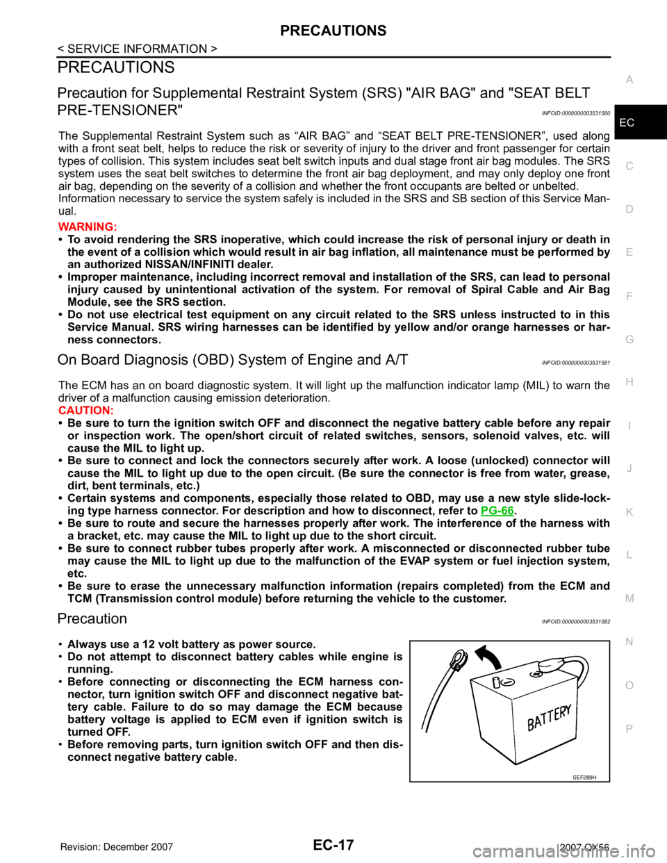
PrecautionINFOID:0000000003531582
•Always use a 12 volt battery as power source.
•Do not attempt to disconnect battery cables while engine is
running.
•Before connecting or disconnecting the ECM harness con-
nector, turn ignition switch OFF and disconnect negative bat-
tery cable. Failure to do so may damage the ECM because
battery voltage is applied to ECM even if ignition switch is
turned OFF.
•Before removing parts, turn ignition switch OFF and then dis-
connect negative battery cable.
SEF289H