check engine ISUZU KB P190 2007 Workshop Repair Manual
[x] Cancel search | Manufacturer: ISUZU, Model Year: 2007, Model line: KB P190, Model: ISUZU KB P190 2007Pages: 6020, PDF Size: 70.23 MB
Page 3829 of 6020

Automatic Transmission – 4L60E – Electrical Diagnosis Page 7C2–43
Step Action Yes No
5 Perform the following procedure to verify the repair:
1 On Tech 2 select: Diagnostic Trouble Codes / Clear Engine & Transmission
DTCs.
2 Follow the instructions on Tech 2 and clear any DTCs.
3 Start the engine.
4 On Tech 2 select:
Diagnostic Trouble Codes / Read DTC Information.
Have any of the DTCs in this procedure set? Go to Step 2 Go to Step 6
6 On Tech 2 select:
Diagnostic Trouble Codes / Read DTC Information.
Does Tech 2 display any DTCs you have not diagnosed? Refer to
4.8 Diagnostic Trouble Code List System OK
When all diagnosis and repairs are completed, check the
system for correct operation.
4.13 DTC P0711 to P0713 – Transmission
Fluid Temperature Sensor
DTC Description
This diagnostic procedure supports the following DTCs:
• DTC P0711 – Transmission Fluid Temperature (TFT) Sensor Performance,
• DTC P0712 – Transmission Fluid Temperature (TFT) Sensor Circuit Low Voltage, and
• DTC P0713 – Transmission Fluid Temperature (TFT) Sensor Circuit High Voltage.
Circuit Description
The automatic transmission fluid temperature (TFT) sensor is part of the automatic transmission fluid pressure (TFP)
manual valve position switch. The automatic TFT sensor is a negative coefficient thermistor. The transmission control
module (TCM) supplies a 5 volt reference signal to the sensor and measures the voltage drop in the circuit. W hen the
transmission fluid is cold, the sensor resistance is high and the TCM detects high signal voltage. As the fluid temperature
increases, the resistance of the sensor decreases, which lowers the signal voltage. This diagnostic monitors the TFT
circuit. The circuit may be functional, but not in the normal operating range. This diagnostic indicates stuck, erratic,
intermittent, skewed, or inaccurate values, indicating poor system performance. The TFT range is -40 – 151°C.
Refer to 2 W iring Diagrams and Connector Chart to aid in diagnosis.
Conditions for Running the DTC
DTC P0711
• No DTC P0117, P0118, P0722 or P0723.
• DTC P0711 has not passed in the current ignition cycle.
• The engine run time is greater than 5 seconds.
• The transmission fluid temperature is -39 – 149°C.
• For conditions 1 and 2 in Conditions for Setting the DTC, the engine coolant temperature is greater than 70°C and
has changed by at least 50°C since start-up.
• For conditions 1 and 2 in Conditions for Setting the DTC, the TCC slip speed is 120 r.p.m. or greater for
600 seconds (10 minutes) cumulatively.
DTC P0712
The engine run time is greater than 5 seconds.
BACK TO CHAPTER INDEX
TO MODEL INDEX
ISUZU KB P190 2007
Page 3831 of 6020
Automatic Transmission – 4L60E – Electrical Diagnosis Page 7C2–45
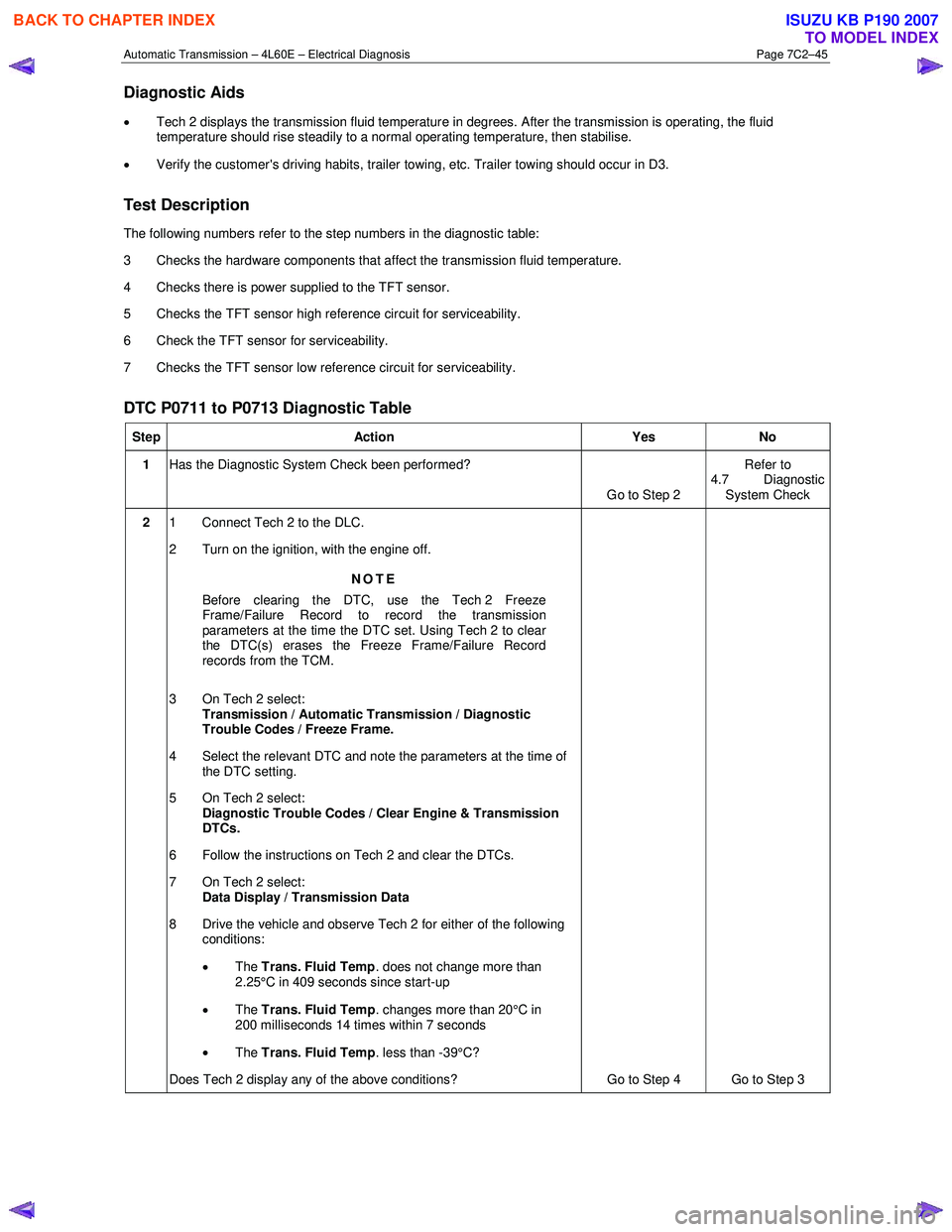
Diagnostic Aids
• Tech 2 displays the transmission fluid temperature in degrees. After the transmission is operating, the fluid
temperature should rise steadily to a normal operating temperature, then stabilise.
• Verify the customer's driving habits, trailer towing, etc. Trailer towing should occur in D3.
Test Description
The following numbers refer to the step numbers in the diagnostic table:
3 Checks the hardware components that affect the transmission fluid temperature.
4 Checks there is power supplied to the TFT sensor.
5 Checks the TFT sensor high reference circuit for serviceability.
6 Check the TFT sensor for serviceability.
7 Checks the TFT sensor low reference circuit for serviceability.
DTC P0711 to P0713 Diagnostic Table
Step Action Yes No
1 Has the Diagnostic System Check been performed?
Go to Step 2 Refer to
4.7 Diagnostic System Check
2 1 Connect Tech 2 to the DLC.
2 Turn on the ignition, with the engine off.
NOTE
Before clearing the DTC, use the Tech 2 Freeze
Frame/Failure Record to record the transmission
parameters at the time the DTC set. Using Tech 2 to clear
the DTC(s) erases the Freeze Frame/Failure Record
records from the TCM.
3 On Tech 2 select: Transmission / Automatic Transmission / Diagnostic
Trouble Codes / Freeze Frame.
4 Select the relevant DTC and note the parameters at the time of the DTC setting.
5 On Tech 2 select:
Diagnostic Trouble Codes / Clear Engine & Transmission
DTCs.
6 Follow the instructions on Tech 2 and clear the DTCs.
7 On Tech 2 select: Data Display / Transmission Data
8 Drive the vehicle and observe Tech 2 for either of the following conditions:
• The Trans. Fluid Temp . does not change more than
2.25°C in 409 seconds since start-up
• The Trans. Fluid Temp . changes more than 20°C in
200 milliseconds 14 times within 7 seconds
• The Trans. Fluid Temp . less than -39°C?
Does Tech 2 display any of the above conditions? Go to Step 4 Go to Step 3
BACK TO CHAPTER INDEX
TO MODEL INDEX
ISUZU KB P190 2007
Page 3833 of 6020
Automatic Transmission – 4L60E – Electrical Diagnosis Page 7C2–47
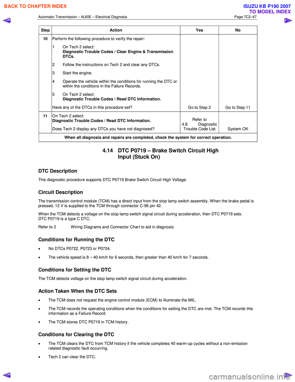
Step Action Yes No
10 Perform the following procedure to verify the repair:
1 On Tech 2 select: Diagnostic Trouble Codes / Clear Engine & Transmission
DTCs.
2 Follow the instructions on Tech 2 and clear any DTCs.
3 Start the engine.
4 Operate the vehicle within the conditions for running the DTC or within the conditions in the Failure Records.
5 On Tech 2 select:
Diagnostic Trouble Codes / Read DTC Information.
Have any of the DTCs in this procedure set? Go to Step 2 Go to Step 11
11 On Tech 2 select:
Diagnostic Trouble Codes / Read DTC Information.
Does Tech 2 display any DTCs you have not diagnosed? Refer to
4.8 Diagnostic Trouble Code List System OK
When all diagnosis and repairs are completed, check the
system for correct operation.
4.14 DTC P0719 – Brake Switch Circuit High
Input (Stuck On)
DTC Description
This diagnostic procedure supports DTC P0719 Brake Switch Circuit High Voltage.
Circuit Description
The transmission control module (TCM) has a direct input from the stop lamp switch assembly. W hen the brake pedal is
pressed, 12 V is supplied to the TCM through connector C-96 pin 42.
W hen the TCM detects a voltage on the stop lamp switch signal circuit during acceleration, then DTC P0719 sets.
DTC P0719 is a type C DTC.
Refer to 2 W iring Diagrams and Connector Chart to aid in diagnosis.
Conditions for Running the DTC
• No DTCs P0722, P0723 or P0724.
• The vehicle speed is 8 – 40 km/h for 6 seconds, then greater than 40 km/h for 7 seconds.
Conditions for Setting the DTC
The TCM detects voltage on the stop lamp switch signal circuit during acceleration.
Action Taken When the DTC Sets
•
The TCM does not request the engine control module (ECM) to illuminate the MIL.
• The TCM records the operating conditions when the conditions for setting the DTC are met. The TCM records this
information as a Failure Record.
• The TCM stores DTC P0719 in TCM history.
Conditions for Clearing the DTC
• The TCM clears the DTC from TCM history if the vehicle completes 40 warm-up cycles without a non-emission
related diagnostic fault occurring.
• Tech 2 can clear the DTC.
BACK TO CHAPTER INDEX
TO MODEL INDEX
ISUZU KB P190 2007
Page 3834 of 6020
Automatic Transmission – 4L60E – Electrical Diagnosis Page 7C2–48
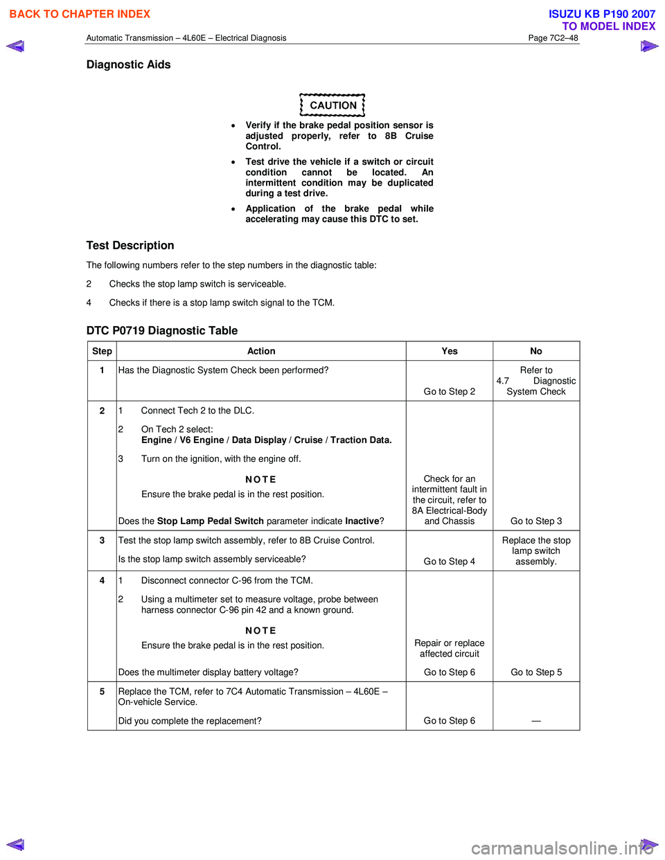
Diagnostic Aids
• Verify if the brake pedal position sensor is
adjusted properly, refer to 8B Cruise
Control.
• Test drive the vehicle if a switch or circuit
condition cannot be located. An
intermittent condition may be duplicated
during a test drive.
• Application of the brake pedal while
accelerating may cause this DTC to set.
Test Description
The following numbers refer to the step numbers in the diagnostic table:
2 Checks the stop lamp switch is serviceable.
4 Checks if there is a stop lamp switch signal to the TCM.
DTC P0719 Diagnostic Table
Step Action Yes No
1 Has the Diagnostic System Check been performed?
Go to Step 2 Refer to
4.7 Diagnostic System Check
2 1 Connect Tech 2 to the DLC.
2 On Tech 2 select: Engine / V6 Engine / Data Display / Cruise / Traction Data.
3 Turn on the ignition, with the engine off.
NOTE
Ensure the brake pedal is in the rest position.
Does the Stop Lamp Pedal Switch parameter indicate Inactive? Check for an
intermittent fault in
the circuit, refer to
8A Electrical-Body and Chassis Go to Step 3
3 Test the stop lamp switch assembly, refer to 8B Cruise Control.
Is the stop lamp switch assembly serviceable? Go to Step 4 Replace the stop
lamp switch
assembly.
4 1 Disconnect connector C-96 from the TCM.
2 Using a multimeter set to measure voltage, probe between harness connector C-96 pin 42 and a known ground.
NOTE
Ensure the brake pedal is in the rest position.
Does the multimeter display battery voltage? Repair or replace
affected circuit
Go to Step 6 Go to Step 5
5
Replace the TCM, refer to 7C4 Automatic Transmission – 4L60E –
On-vehicle Service.
Did you complete the replacement? Go to Step 6
—
BACK TO CHAPTER INDEX
TO MODEL INDEX
ISUZU KB P190 2007
Page 3835 of 6020

Automatic Transmission – 4L60E – Electrical Diagnosis Page 7C2–49
Step Action Yes No
6 Perform the following procedure to verify the repair:
1 On Tech 2 select: Diagnostic Trouble Codes / Clear Engine & Transmission
DTCs
2 Follow the instructions on Tech 2 and clear any DTCs.
3 Operate the vehicle under the following conditions:
• Turn on the ignition, with the engine off for at least
2 seconds.
• Start the vehicle and idle for 5 seconds.
• Drive in D4 from 0 – 60 km/h 8 times in 1 ignition cycle.
4 On Tech 2 select:
Diagnostic Trouble Codes / Read DTC Information.
Has DTC P0719 set? Go to Step 2 Go to Step 7
7 On Tech 2 select:
Diagnostic Trouble Codes / Read DTC Information.
Does Tech 2 display any DTCs you have not diagnosed? Refer to
4.8 Diagnostic Trouble Code List System OK
When all diagnosis and repairs are completed, check the
system for correct operation.
4.15 DTC P0722 – Vehicle Speed Sensor
Circuit Low Voltage
DTC Description
This diagnostic procedure supports DTC P0722 Vehicle Speed Sensor Circuit Low Voltage.
Circuit Description
The vehicle speed sensor (VSS) provides vehicle speed information to the transmission control module (TCM). The VSS
is a permanent magnet generator. The sensor is mounted in the extension housing facing the rear internal gear which is
splined to the output shaft assembly. As the output shaft and internal gear rotate, the toothed rotor of the internal gear
produces AC voltage as the rotor teeth pass through the magnetic field of the sensor. The AC voltage level and the
number of pulses increase as the speed of the vehicle increases. The TCM converts the voltage to vehicle speed. The
TCM uses the output shaft speed signal to determine shift timing and torque converter clutch (TCC) scheduling.
If the TCM detects no vehicle speed when there is engine speed in a drive gear range, then DTC P0722 sets.
DTC P0722 is a type B DTC.
Refer to 2 W iring Diagrams and Connector Chart to aid in diagnosis.
Conditions for Running the DTC
• No DTCs P0723, P1810, P1815 or P1816.
• Ignition voltage is 8 – 18 V.
• TFT is -40°C – 150°C.
• The engine run time is greater than 5 seconds.
• The throttle position is greater than 12 percent.
• The engine torque is 108 – 882 Nm.
Conditions for Setting the DTC
The transmission output shaft speed is less than 50 r.p.m. for 3 seconds.
BACK TO CHAPTER INDEX
TO MODEL INDEX
ISUZU KB P190 2007
Page 3836 of 6020
Automatic Transmission – 4L60E – Electrical Diagnosis Page 7C2–50
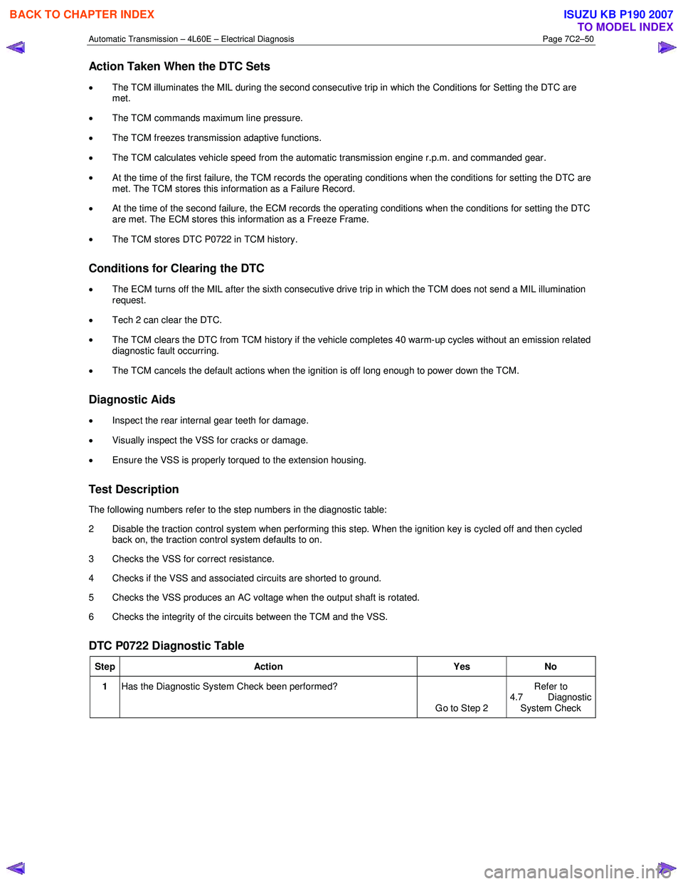
Action Taken When the DTC Sets
• The TCM illuminates the MIL during the second consecutive trip in which the Conditions for Setting the DTC are
met.
• The TCM commands maximum line pressure.
• The TCM freezes transmission adaptive functions.
• The TCM calculates vehicle speed from the automatic transmission engine r.p.m. and commanded gear.
• At the time of the first failure, the TCM records the operating conditions when the conditions for setting the DTC are
met. The TCM stores this information as a Failure Record.
• At the time of the second failure, the ECM records the operating conditions when the conditions for setting the DTC
are met. The ECM stores this information as a Freeze Frame.
• The TCM stores DTC P0722 in TCM history.
Conditions for Clearing the DTC
• The ECM turns off the MIL after the sixth consecutive drive trip in which the TCM does not send a MIL illumination
request.
• Tech 2 can clear the DTC.
• The TCM clears the DTC from TCM history if the vehicle completes 40 warm-up cycles without an emission related
diagnostic fault occurring.
• The TCM cancels the default actions when the ignition is off long enough to power down the TCM.
Diagnostic Aids
• Inspect the rear internal gear teeth for damage.
• Visually inspect the VSS for cracks or damage.
• Ensure the VSS is properly torqued to the extension housing.
Test Description
The following numbers refer to the step numbers in the diagnostic table:
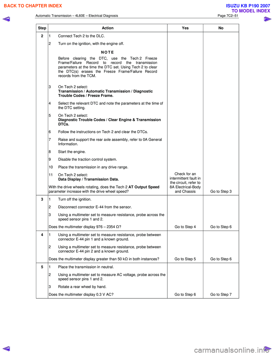
2 Disable the traction control system when performing this step. W hen the ignition key is cycled off and then cycled back on, the traction control system defaults to on.
3 Checks the VSS for correct resistance.
4 Checks if the VSS and associated circuits are shorted to ground.
5 Checks the VSS produces an AC voltage when the output shaft is rotated.
6 Checks the integrity of the circuits between the TCM and the VSS.
DTC P0722 Diagnostic Table
Step Action Yes No
1 Has the Diagnostic System Check been performed?
Go to Step 2 Refer to
4.7 Diagnostic System Check
BACK TO CHAPTER INDEX
TO MODEL INDEX
ISUZU KB P190 2007
Page 3837 of 6020
Automatic Transmission – 4L60E – Electrical Diagnosis Page 7C2–51
Step Action Yes No
2 1 Connect Tech 2 to the DLC.
2 Turn on the ignition, with the engine off.
NOTE
Before clearing the DTC, use the Tech 2 Freeze
Frame/Failure Record to record the transmission
parameters at the time the DTC set. Using Tech 2 to clear
the DTC(s) erases the Freeze Frame/Failure Record
records from the TCM.
3 On Tech 2 select: Transmission / Automatic Transmission / Diagnostic
Trouble Codes / Freeze Frame.
4 Select the relevant DTC and note the parameters at the time of the DTC setting.
5 On Tech 2 select:
Diagnostic Trouble Codes / Clear Engine & Transmission
DTCs.
6 Follow the instructions on Tech 2 and clear the DTCs.
7 Raise and support the rear axle assembly, refer to 0A General Information.
8 Start the engine.
9 Disable the traction control system.
10 Place the transmission in any drive range.
11 On Tech 2 select: Data Display / Transmission Data.
W ith the drive wheels rotating, does the Tech 2 AT Output Speed
parameter increase with the drive wheel speed? Check for an
intermittent fault in the circuit, refer to
8A Electrical-Body and Chassis Go to Step 3
3 1 Turn off the ignition.
2 Disconnect connector E-44 from the sensor.
3 Using a multimeter set to measure resistance, probe across the speed sensor pins 1 and 2.
Does the multimeter display 976 – 2354 Ω? Go to Step 4 Go to Step 6
4 1 Using a multimeter set to measure resistance, probe between
connector E-44 pin 1 and a known ground.
2 Using a multimeter set to measure resistance, probe between connector E-44 pin 2 and a known ground.
Does the multimeter display greater than 50 k Ω in both instances? Go to Step 5 Go to Step 6
5 1 Place the transmission in neutral.
2 Using a multimeter set to measure AC voltage, probe across the speed sensor pins 1 and 2.
3 Rotate a rear wheel by hand.
Does the multimeter display 0.3 V AC? Go to Step 6 Go to Step 7
BACK TO CHAPTER INDEX
TO MODEL INDEX
ISUZU KB P190 2007
Page 3838 of 6020

Automatic Transmission – 4L60E – Electrical Diagnosis Page 7C2–52
Step Action Yes No
6 1 Disconnect connector C-96 from the TCM.
2 Test circuits speed sensor circuits (between C-96 pin 16 and E-44 pin 2; C-96 pin 41 and E-44 pin 1) for the following
conditions:
• Short to ground
• Open circuit
• Short together
Did you find and correct the condition? Go to Step 9 Go to Step 8
7 Replace the vehicle speed sensor, refer to 7C4 Automatic
Transmission – 4L60E – On-vehicle Service.
Did you complete the replacement? Go to Step 9 —
8 Replace the TCM, refer to 7C4 Automatic Transmission – 4L60E –
On-vehicle Service.
Did you complete the replacement? Go to Step 9 —
9 Perform the following procedure to verify the repair:
1 On Tech 2 select: Diagnostic Trouble Codes / Clear Engine & Transmission
DTCs.
2 Follow the instructions on Tech 2 and clear any DTCs.
3 Operate the vehicle so the transmission output speed is greater than 500 r.p.m. for 3 seconds.
4 On Tech 2 select:
Diagnostic Trouble Codes / Read DTC Information.
Has DTC P0722 set? Go to Step 2 Go to Step 9
10 On Tech 2 select:
Diagnostic Trouble Codes / Read DTC Information.
Does Tech 2 display any DTCs you have not diagnosed? Refer to
4.8 Diagnostic Trouble Code List System OK
When all diagnosis and repairs are completed, check the system for correct operation.
4.16 DTC P0723 – Vehicle Speed Sensor
Circuit Intermittent
DTC Description
This diagnostic procedure supports DTC P0723 Vehicle Speed Sensor Circuit Intermittent.
Circuit Description
The vehicle speed sensor (VSS) provides vehicle speed information to the transmission control module (TCM). The VSS
is a permanent magnet generator. The sensor is mounted in the extension housing facing the rear internal gear which is
splined to the output shaft assembly. As the output shaft and internal gear rotate, the toothed rotor of the internal gear
produces AC voltage as the rotor teeth pass through the magnetic field of the sensor. The AC voltage level and the
number of pulses increase as the speed of the vehicle increases. The TCM converts the voltage to vehicle speed. The
TCM uses the output shaft speed signal to determine shift timing and torque converter clutch (TCC) scheduling.
If the TCM detects an unrealistic drop in output shaft speed, DTC P0723 sets. DTC P0723 is a type B DTC.
Refer to 2 W iring Diagrams and Connector Chart to aid in diagnosis.
Conditions for Running the DTC
• No DTCs P0722, P1810, P1815 or P1816.
BACK TO CHAPTER INDEX
TO MODEL INDEX
ISUZU KB P190 2007
Page 3839 of 6020
Automatic Transmission – 4L60E – Electrical Diagnosis Page 7C2–53
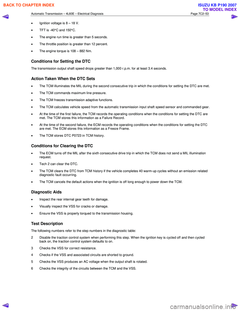
• Ignition voltage is 8 – 18 V.
• TFT is -40°C and 150°C.
• The engine run time is greater than 5 seconds.
• The throttle position is greater than 12 percent.
• The engine torque is 108 – 882 Nm.
Conditions for Setting the DTC
The transmission output shaft speed drops greater than 1,000 r.p.m. for at least 3.4 seconds.
Action Taken When the DTC Sets
• The TCM illuminates the MIL during the second consecutive trip in which the conditions for setting the DTC are met.
• The TCM commands maximum line pressure.
• The TCM freezes transmission adaptive functions.
• The TCM calculates vehicle speed from the automatic transmission input shaft speed sensor and commanded gear.
• At the time of the first failure, the TCM records the operating conditions when the conditions for setting the DTC are
met. The TCM stores this information as a Failure Record.
• At the time of the second failure, the ECM records the operating conditions when the conditions for setting the DTC
are met. The ECM stores this information as a Freeze Frame.
• The TCM stores DTC P0723 in TCM history.
Conditions for Clearing the DTC
• The ECM turns off the MIL after the sixth consecutive drive trip in which the TCM does not send a MIL illumination
request.
• Tech 2 can clear the DTC.
• The TCM clears the DTC from TCM history if the vehicle completes 40 warm-up cycles without an emission related
diagnostic fault occurring.
• The TCM cancels the default actions when the ignition is off long enough to power down the TCM.
Diagnostic Aids
•
Inspect the rear internal gear teeth for damage.
• Visually inspect the VSS for cracks or damage.
• Ensure the VSS is properly torqued to the transmission housing.
Test Description
The following numbers refer to the step numbers in the diagnostic table:
2 Disable the traction control system when performing this step. W hen the ignition key is cycled off and then cycled back on, the traction control system defaults to on.
3 Checks the VSS for correct resistance.
4 Checks if the VSS and associated circuits are shorted to ground.
5 Checks the VSS produces an AC voltage when the output shaft is rotated.
6 Checks the integrity of the circuits between the TCM and the VSS.
BACK TO CHAPTER INDEX
TO MODEL INDEX
ISUZU KB P190 2007
Page 3840 of 6020
Automatic Transmission – 4L60E – Electrical Diagnosis Page 7C2–54
DTC P0723 Diagnostic Table
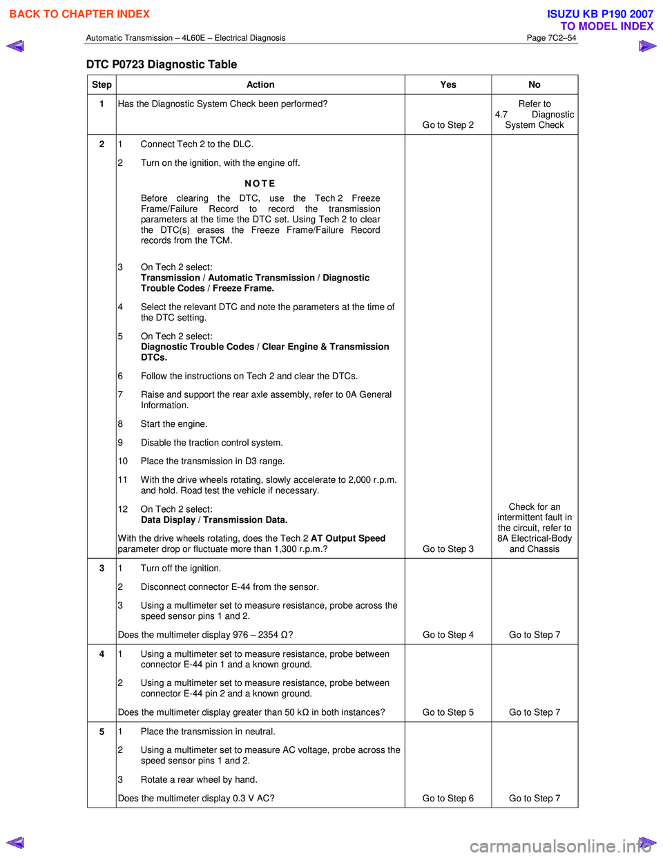
Step Action Yes No
1 Has the Diagnostic System Check been performed?
Go to Step 2 Refer to
4.7 Diagnostic System Check
2 1 Connect Tech 2 to the DLC.
2 Turn on the ignition, with the engine off.
NOTE
Before clearing the DTC, use the Tech 2 Freeze
Frame/Failure Record to record the transmission
parameters at the time the DTC set. Using Tech 2 to clear
the DTC(s) erases the Freeze Frame/Failure Record
records from the TCM.
3 On Tech 2 select: Transmission / Automatic Transmission / Diagnostic
Trouble Codes / Freeze Frame.
4 Select the relevant DTC and note the parameters at the time of the DTC setting.
5 On Tech 2 select:
Diagnostic Trouble Codes / Clear Engine & Transmission
DTCs.
6 Follow the instructions on Tech 2 and clear the DTCs.
7 Raise and support the rear axle assembly, refer to 0A General Information.
8 Start the engine.
9 Disable the traction control system.
10 Place the transmission in D3 range.
11 With the drive wheels rotating, slowly accelerate to 2,000 r.p.m. and hold. Road test the vehicle if necessary.
12 On Tech 2 select: Data Display / Transmission Data.
W ith the drive wheels rotating, does the Tech 2 AT Output Speed
parameter drop or fluctuate more than 1,300 r.p.m.? Go to Step 3 Check for an
intermittent fault in the circuit, refer to
8A Electrical-Body and Chassis
3 1 Turn off the ignition.
2 Disconnect connector E-44 from the sensor.
3 Using a multimeter set to measure resistance, probe across the speed sensor pins 1 and 2.
Does the multimeter display 976 – 2354 Ω? Go to Step 4 Go to Step 7
4 1 Using a multimeter set to measure resistance, probe between
connector E-44 pin 1 and a known ground.
2 Using a multimeter set to measure resistance, probe between connector E-44 pin 2 and a known ground.
Does the multimeter display greater than 50 k Ω in both instances? Go to Step 5 Go to Step 7
5 1 Place the transmission in neutral.
2 Using a multimeter set to measure AC voltage, probe across the speed sensor pins 1 and 2.
3 Rotate a rear wheel by hand.
Does the multimeter display 0.3 V AC? Go to Step 6 Go to Step 7
BACK TO CHAPTER INDEX
TO MODEL INDEX
ISUZU KB P190 2007