ISUZU KB P190 2007 Workshop Repair Manual
Manufacturer: ISUZU, Model Year: 2007, Model line: KB P190, Model: ISUZU KB P190 2007Pages: 6020, PDF Size: 70.23 MB
Page 2621 of 6020
Engine Mechanical – V6 Page 6A1–142
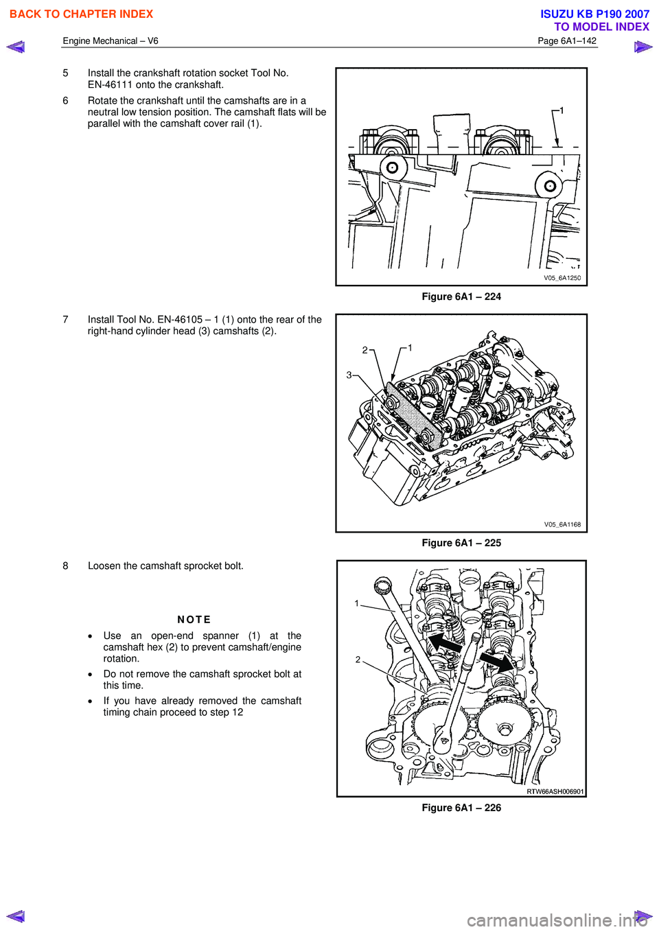
5 Install the crankshaft rotation socket Tool No.
EN-46111 onto the crankshaft.
6 Rotate the crankshaft until the camshafts are in a neutral low tension position. The camshaft flats will be
parallel with the camshaft cover rail (1).
Figure 6A1 – 224
7 Install Tool No. EN-46105 – 1 (1) onto the rear of the right-hand cylinder head (3) camshafts (2).
Figure 6A1 – 225
8 Loosen the camshaft sprocket bolt.
NOTE
• Use an open-end spanner (1) at the
camshaft hex (2) to prevent camshaft/engine
rotation.
• Do not remove the camshaft sprocket bolt at
this time.
• If you have already removed the camshaft
timing chain proceed to step 12
Figure 6A1 – 226
BACK TO CHAPTER INDEX
TO MODEL INDEX
ISUZU KB P190 2007
Page 2622 of 6020
Engine Mechanical – V6 Page 6A1–143
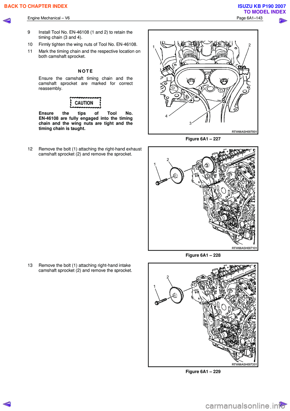
9 Install Tool No. EN-46108 (1 and 2) to retain the
timing chain (3 and 4).
10 Firmly tighten the wing nuts of Tool No. EN-46108.
11 Mark the timing chain and the respective location on both camshaft sprocket.
NOTE
Ensure the camshaft timing chain and the
camshaft sprocket are marked for correct
reassembly.
CAUTION
Ensure the tips of Tool No.
EN-46108 are fully engaged into the timing
chain and the wing nuts are tight and the
timing chain is taught.
Figure 6A1 – 227
12 Remove the bolt (1) attaching the right-hand exhaust camshaft sprocket (2) and remove the sprocket.
Figure 6A1 – 228
13 Remove the bolt (1) attaching right-hand intake camshaft sprocket (2) and remove the sprocket.
Figure 6A1 – 229
BACK TO CHAPTER INDEX
TO MODEL INDEX
ISUZU KB P190 2007
Page 2623 of 6020
Engine Mechanical – V6 Page 6A1–144
Left-hand Side
1 Remove the left-hand camshaft cover, refer to 3.12 Camshaft Cover.
2 Remove the camshaft position sensors, refer to 6C1-3 Engine Management – V6 – Service Operations.
3 Remove the camshaft position actuator solenoids, refer to 6C1-3 Engine Management – V6 – Service Operations.
4 Remove the crankshaft balancer assembly, refer to 3.13 Crankshaft Balancer Assembly.
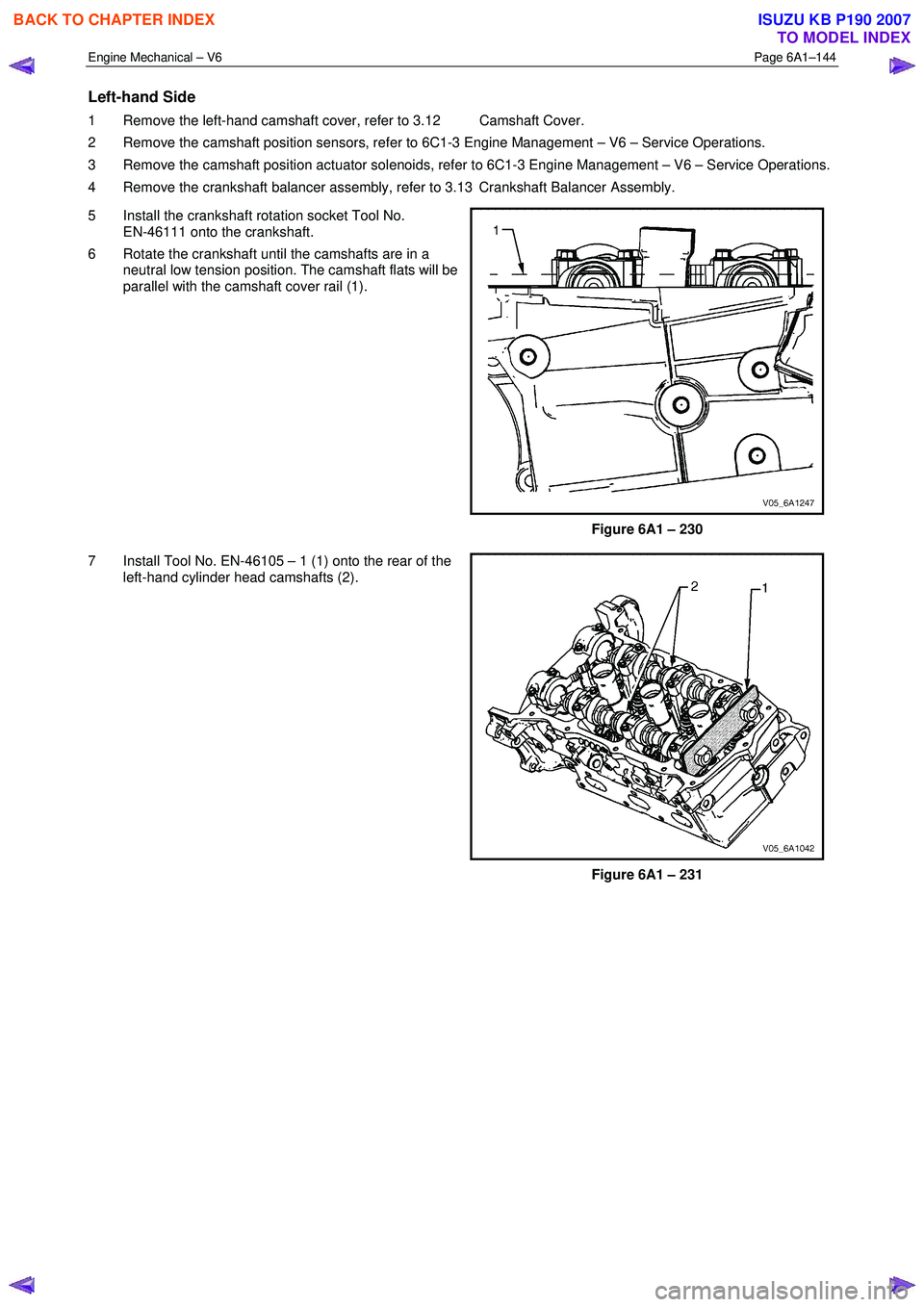
5 Install the crankshaft rotation socket Tool No. EN-46111 onto the crankshaft.
6 Rotate the crankshaft until the camshafts are in a neutral low tension position. The camshaft flats will be
parallel with the camshaft cover rail (1).
Figure 6A1 – 230
7 Install Tool No. EN-46105 – 1 (1) onto the rear of the left-hand cylinder head camshafts (2).
Figure 6A1 – 231
BACK TO CHAPTER INDEX
TO MODEL INDEX
ISUZU KB P190 2007
Page 2624 of 6020
Engine Mechanical – V6 Page 6A1–145
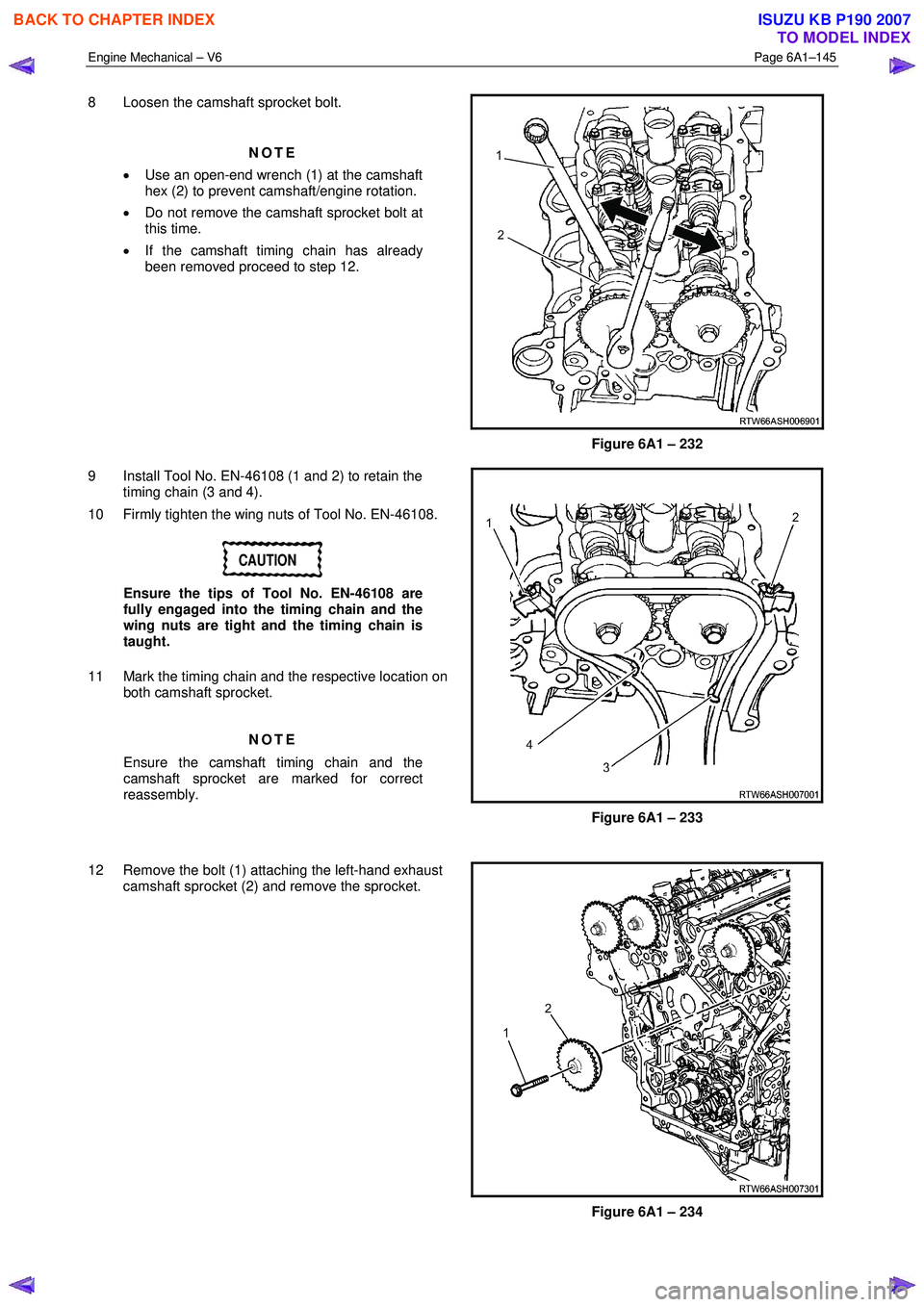
8 Loosen the camshaft sprocket bolt.
NOTE
• Use an open-end wrench (1) at the camshaft
hex (2) to prevent camshaft/engine rotation.
• Do not remove the camshaft sprocket bolt at
this time.
• If the camshaft timing chain has already
been removed proceed to step 12.
Figure 6A1 – 232
9 Install Tool No. EN-46108 (1 and 2) to retain the timing chain (3 and 4).
10 Firmly tighten the wing nuts of Tool No. EN-46108.
CAUTION
Ensure the tips of Tool No. EN-46108 are
fully engaged into the timing chain and the
wing nuts are tight and the timing chain is
taught.
11 Mark the timing chain and the respective location on both camshaft sprocket.
NOTE
Ensure the camshaft timing chain and the
camshaft sprocket are marked for correct
reassembly.
Figure 6A1 – 233
12 Remove the bolt (1) attaching the left-hand exhaust camshaft sprocket (2) and remove the sprocket.
Figure 6A1 – 234
BACK TO CHAPTER INDEX
TO MODEL INDEX
ISUZU KB P190 2007
Page 2625 of 6020
Engine Mechanical – V6 Page 6A1–146
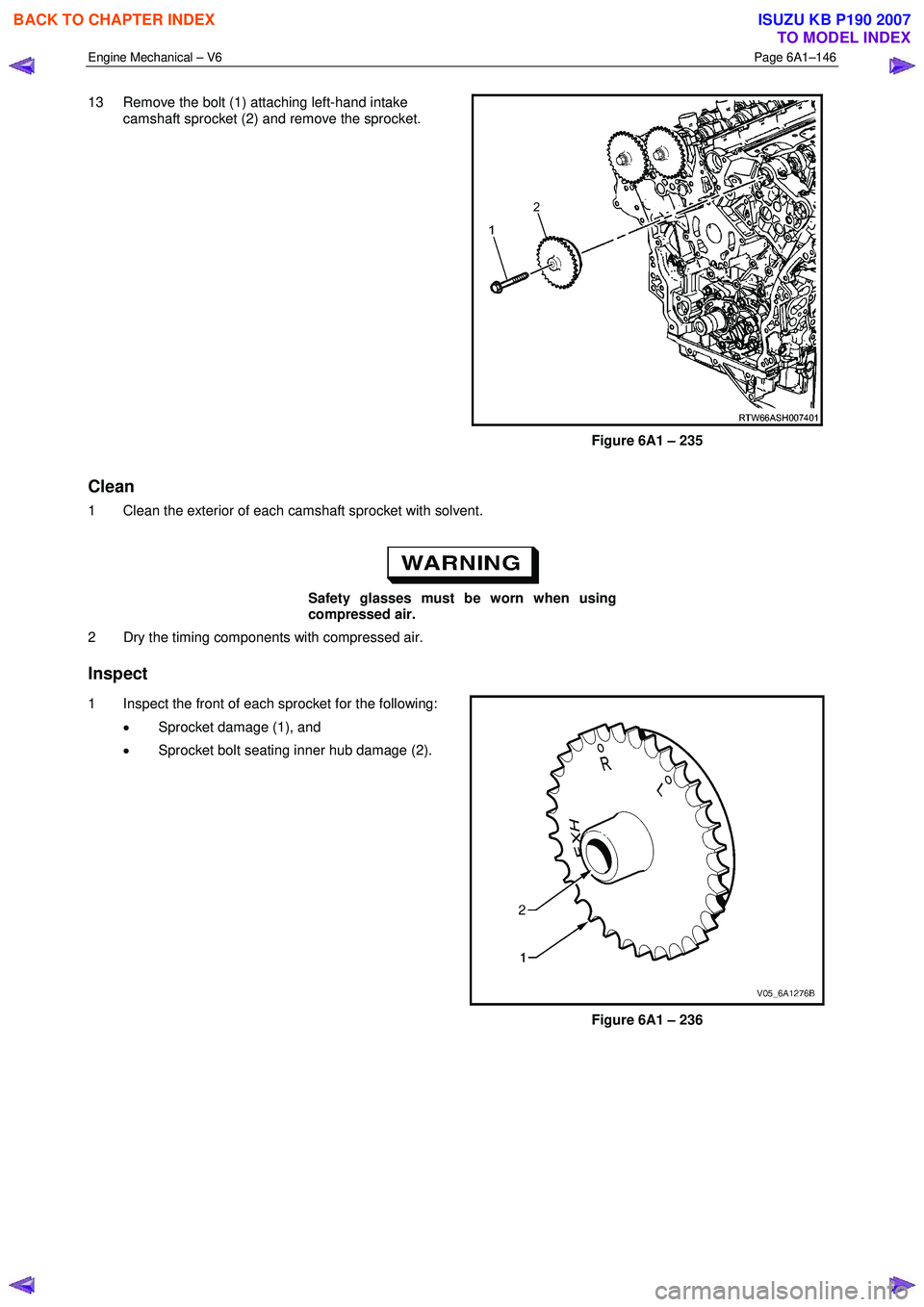
13 Remove the bolt (1) attaching left-hand intake
camshaft sprocket (2) and remove the sprocket.
Figure 6A1 – 235
Clean
1 Clean the exterior of each camshaft sprocket with solvent.
Safety glasses must be worn when using
compressed air.
2 Dry the timing components with compressed air.
Inspect
1 Inspect the front of each sprocket for the following:
• Sprocket damage (1), and
• Sprocket bolt seating inner hub damage (2).
Figure 6A1 – 236
BACK TO CHAPTER INDEX
TO MODEL INDEX
ISUZU KB P190 2007
Page 2626 of 6020

Engine Mechanical – V6 Page 6A1–147
2 Inspect the back of each sprocket for the following:
• Sprocket damage (1),
• Camshaft locating pin damage (2) and,
• Camshaft seating/sealing inner hub flange
damage (3),
NOTE
These checks apply to both the inlet and
exhaust camshaft sprockets.
Figure 6A1 – 237
Reinstall
Reinstallation of the camshaft sprockets is the reverse of the removal procedure, noting the following:
1 Align the sprockets and timing chain with the marks made during removal.
2 Tighten the camshaft sprocket bolts to the correct torque specification.
Camshaft sprocket attaching
bolt torque specification ..........................49.0 – 67.0 Nm
3 Remove the timing chain retention tools.
3.19 Camshaft
Remove
Right-hand Side
1 Remove the right-hand cylinder head camshaft sprockets, refer to 3.18 Camshaft Sprocket.
2 Remove the Tool No. EN-46105 – 1 (1) from the right- hand cylinder head camshafts (2).
NOTE
Tool No. EN-46105 was installed as part of the
right-hand cylinder head camshaft sprocket
removal procedure.
Figure 6A1 – 238
BACK TO CHAPTER INDEX
TO MODEL INDEX
ISUZU KB P190 2007
Page 2627 of 6020
Engine Mechanical – V6 Page 6A1–148
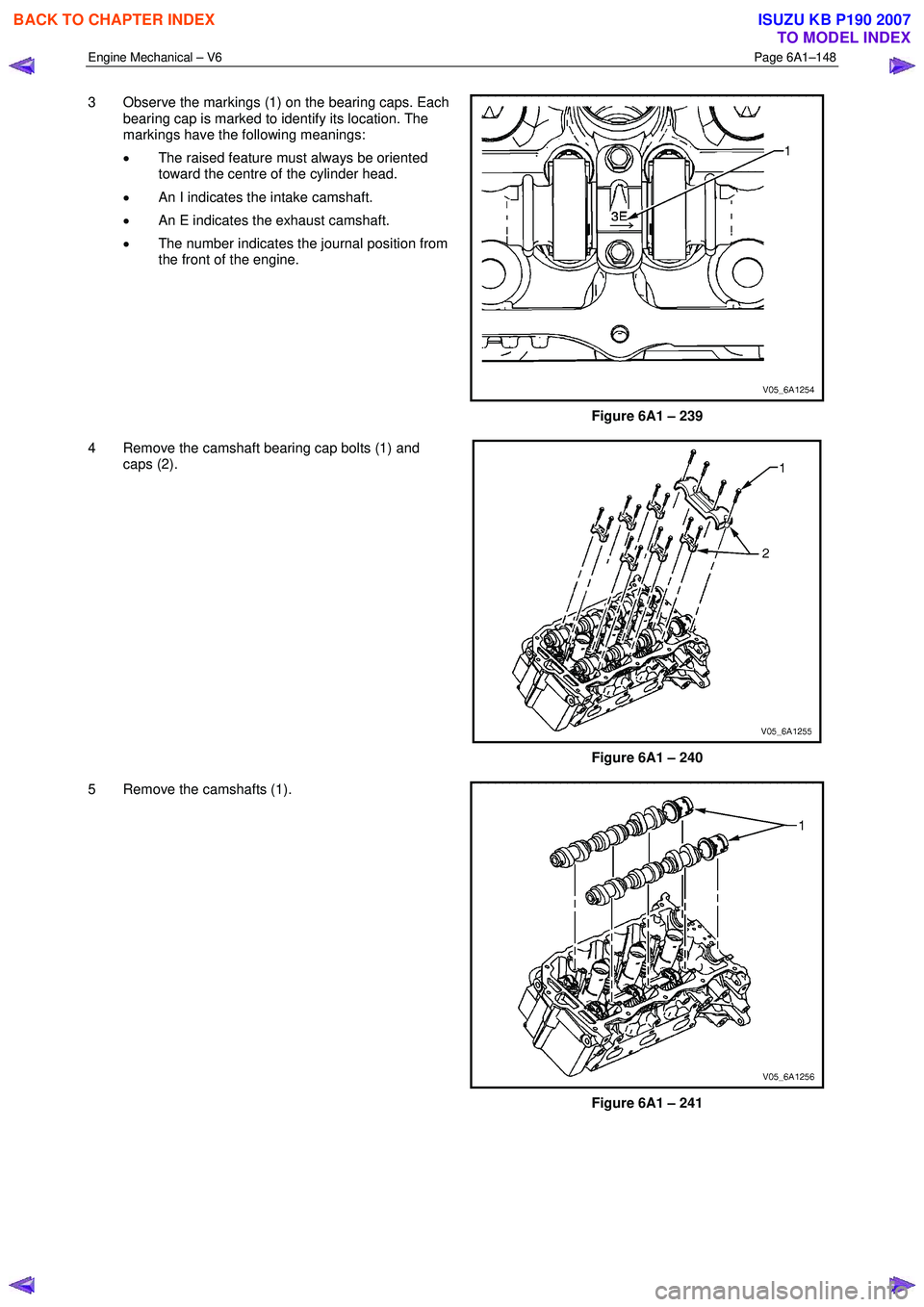
3 Observe the markings (1) on the bearing caps. Each
bearing cap is marked to identify its location. The
markings have the following meanings:
• The raised feature must always be oriented
toward the centre of the cylinder head.
• An I indicates the intake camshaft.
• An E indicates the exhaust camshaft.
• The number indicates the journal position from
the front of the engine.
Figure 6A1 – 239
4 Remove the camshaft bearing cap bolts (1) and caps (2).
Figure 6A1 – 240
5 Remove the camshafts (1).
Figure 6A1 – 241
BACK TO CHAPTER INDEX
TO MODEL INDEX
ISUZU KB P190 2007
Page 2628 of 6020
Engine Mechanical – V6 Page 6A1–149
Left-hand Side
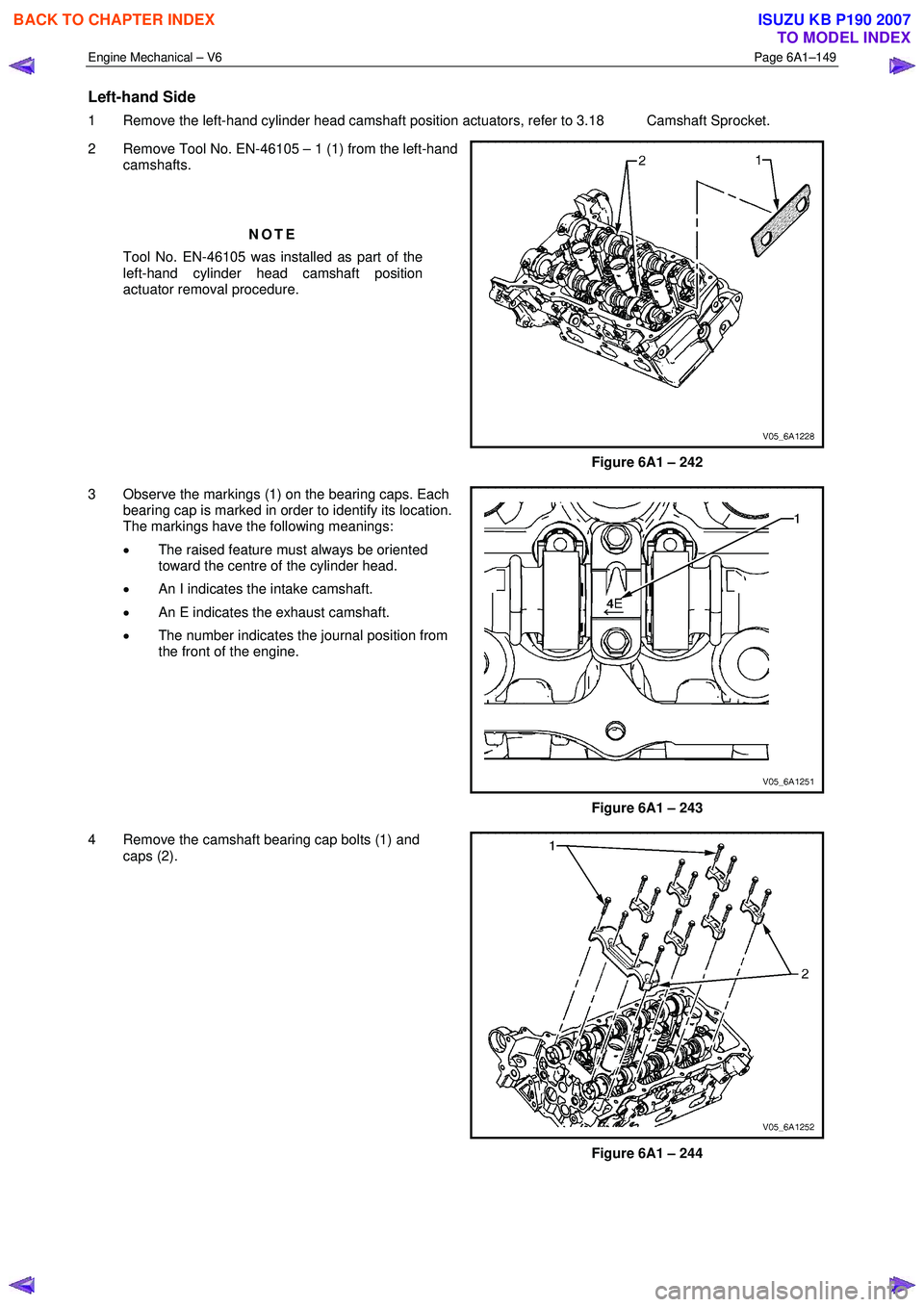
1 Remove the left-hand cylinder head camshaft position actuators, refer to 3.18 Camshaft Sprocket.
2 Remove Tool No. EN-46105 – 1 (1) from the left-hand camshafts.
NOTE
Tool No. EN-46105 was installed as part of the
left-hand cylinder head camshaft position
actuator removal procedure.
Figure 6A1 – 242
3 Observe the markings (1) on the bearing caps. Each bearing cap is marked in order to identify its location.
The markings have the following meanings:
• The raised feature must always be oriented
toward the centre of the cylinder head.
• An I indicates the intake camshaft.
• An E indicates the exhaust camshaft.
• The number indicates the journal position from
the front of the engine.
Figure 6A1 – 243
4 Remove the camshaft bearing cap bolts (1) and caps (2).
Figure 6A1 – 244
BACK TO CHAPTER INDEX
TO MODEL INDEX
ISUZU KB P190 2007
Page 2629 of 6020
Engine Mechanical – V6 Page 6A1–150
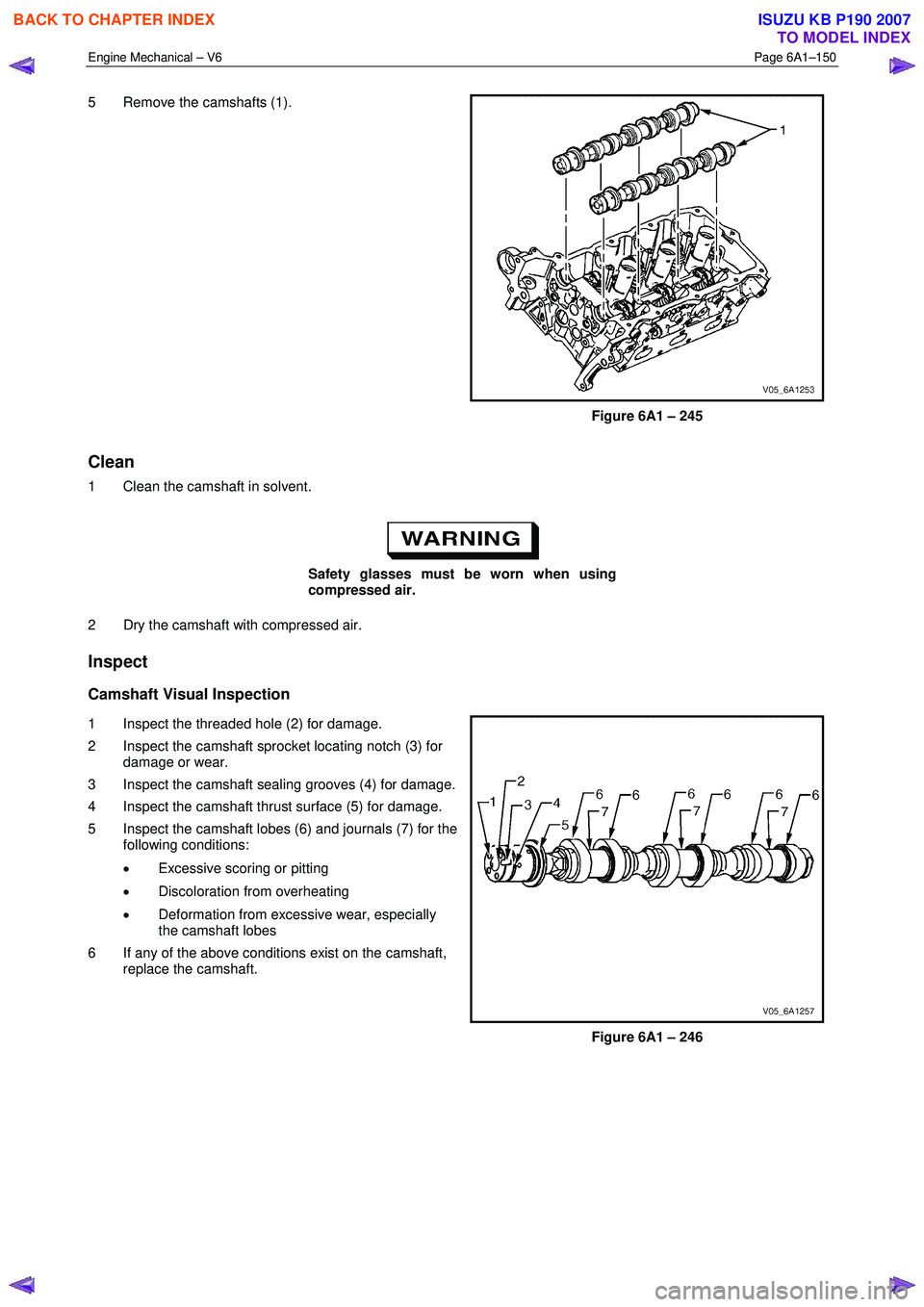
5 Remove the camshafts (1).
Figure 6A1 – 245
Clean
1 Clean the camshaft in solvent.
Safety glasses must be worn when using
compressed air.
2 Dry the camshaft with compressed air.
Inspect
Camshaft Visual Inspection
1 Inspect the threaded hole (2) for damage.
2 Inspect the camshaft sprocket locating notch (3) for damage or wear.
3 Inspect the camshaft sealing grooves (4) for damage.
4 Inspect the camshaft thrust surface (5) for damage.
5 Inspect the camshaft lobes (6) and journals (7) for the following conditions:
• Excessive scoring or pitting
• Discoloration from overheating
• Deformation from excessive wear, especially
the camshaft lobes
6 If any of the above conditions exist on the camshaft, replace the camshaft.
Figure 6A1 – 246
BACK TO CHAPTER INDEX
TO MODEL INDEX
ISUZU KB P190 2007
Page 2630 of 6020
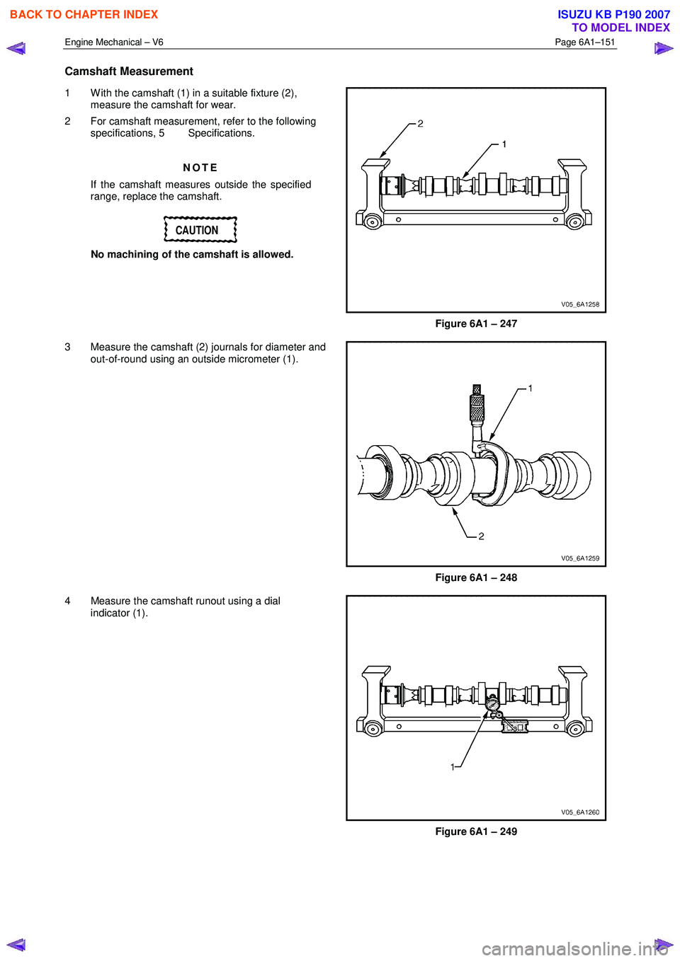
Engine Mechanical – V6 Page 6A1–151
Camshaft Measurement
1 W ith the camshaft (1) in a suitable fixture (2),
measure the camshaft for wear.
2 For camshaft measurement, refer to the following specifications, 5 Specifications.
NOTE
If the camshaft measures outside the specified
range, replace the camshaft.
CAUTION
No machining of the camshaft is allowed.
Figure 6A1 – 247
3 Measure the camshaft (2) journals for diameter and out-of-round using an outside micrometer (1).
Figure 6A1 – 248
4 Measure the camshaft runout using a dial indicator (1).
Figure 6A1 – 249
BACK TO CHAPTER INDEX
TO MODEL INDEX
ISUZU KB P190 2007