ISUZU KB P190 2007 Workshop Repair Manual
Manufacturer: ISUZU, Model Year: 2007, Model line: KB P190, Model: ISUZU KB P190 2007Pages: 6020, PDF Size: 70.23 MB
Page 2611 of 6020
Engine Mechanical – V6 Page 6A1–132
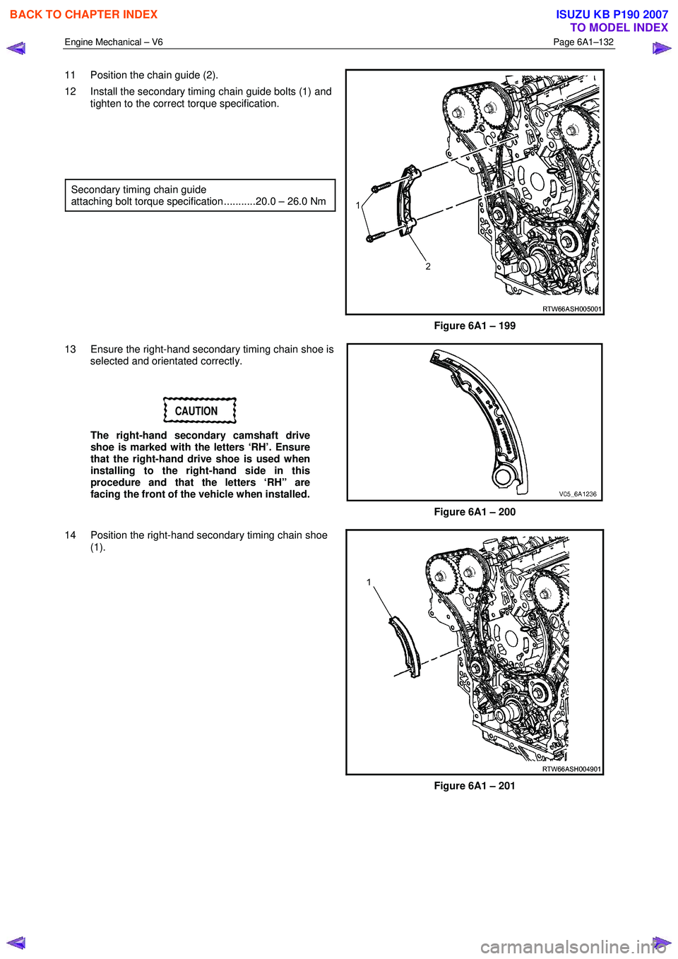
11 Position the chain guide (2).
12 Install the secondary timing chain guide bolts (1) and tighten to the correct torque specification.
Secondary timing chain guide
attaching bolt torque specification ...........20.0 – 26.0 Nm
Figure 6A1 – 199
13 Ensure the right-hand secondary timing chain shoe is selected and orientated correctly.
CAUTION
The right-hand secondary camshaft drive
shoe is marked with the letters ‘RH’. Ensure
that the right-hand drive shoe is used when
installing to the right-hand side in this
procedure and that the letters ‘RH” are
facing the front of the vehicle when installed.
Figure 6A1 – 200
14 Position the right-hand secondary timing chain shoe (1).
Figure 6A1 – 201
BACK TO CHAPTER INDEX
TO MODEL INDEX
ISUZU KB P190 2007
Page 2612 of 6020
Engine Mechanical – V6 Page 6A1–133
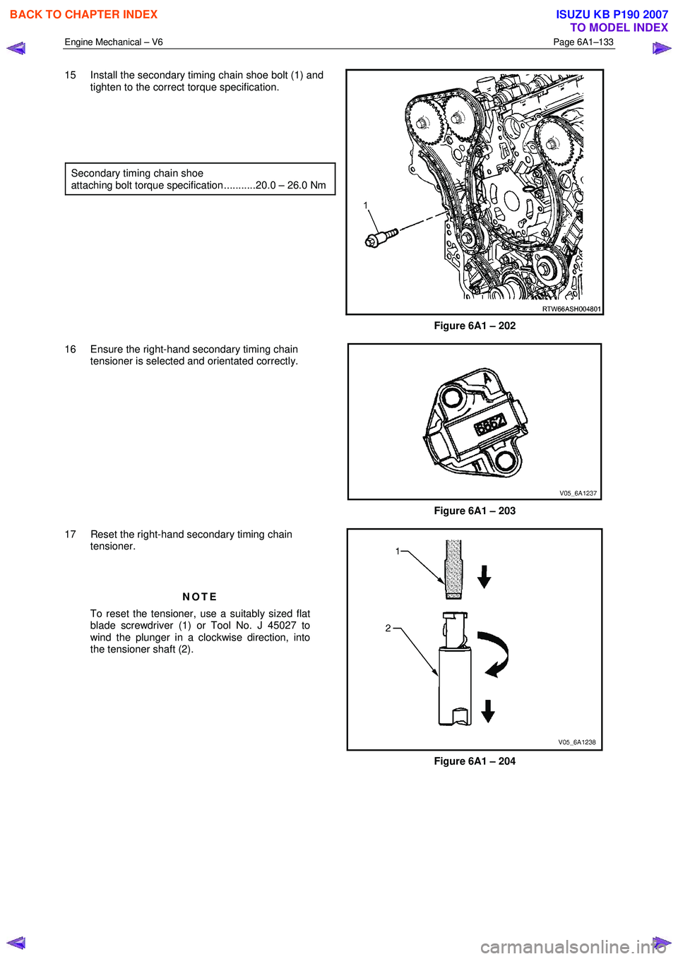
15 Install the secondary timing chain shoe bolt (1) and
tighten to the correct torque specification.
Secondary timing chain shoe
attaching bolt torque specification ...........20.0 – 26.0 Nm
Figure 6A1 – 202
16 Ensure the right-hand secondary timing chain tensioner is selected and orientated correctly.
Figure 6A1 – 203
17 Reset the right-hand secondary timing chain tensioner.
NOTE
To reset the tensioner, use a suitably sized flat
blade screwdriver (1) or Tool No. J 45027 to
wind the plunger in a clockwise direction, into
the tensioner shaft (2).
Figure 6A1 – 204
BACK TO CHAPTER INDEX
TO MODEL INDEX
ISUZU KB P190 2007
Page 2613 of 6020
Engine Mechanical – V6 Page 6A1–134
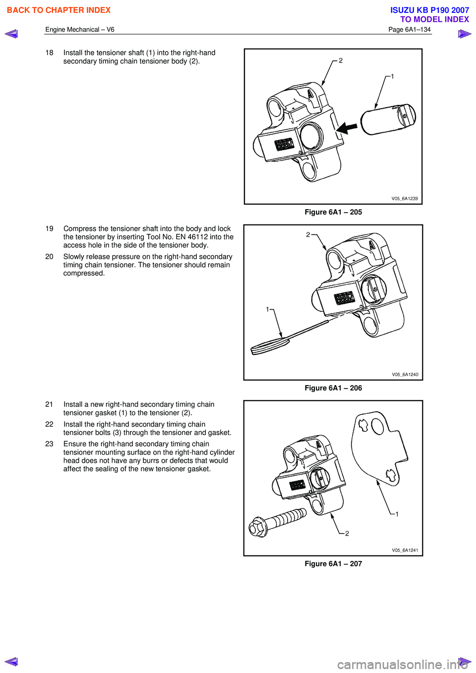
18 Install the tensioner shaft (1) into the right-hand
secondary timing chain tensioner body (2).
Figure 6A1 – 205
19 Compress the tensioner shaft into the body and lock the tensioner by inserting Tool No. EN 46112 into the
access hole in the side of the tensioner body.
20 Slowly release pressure on the right-hand secondary timing chain tensioner. The tensioner should remain
compressed.
Figure 6A1 – 206
21 Install a new right-hand secondary timing chain tensioner gasket (1) to the tensioner (2).
22 Install the right-hand secondary timing chain tensioner bolts (3) through the tensioner and gasket.
23 Ensure the right-hand secondary timing chain tensioner mounting surface on the right-hand cylinder
head does not have any burrs or defects that would
affect the sealing of the new tensioner gasket.
Figure 6A1 – 207
BACK TO CHAPTER INDEX
TO MODEL INDEX
ISUZU KB P190 2007
Page 2614 of 6020
Engine Mechanical – V6 Page 6A1–135
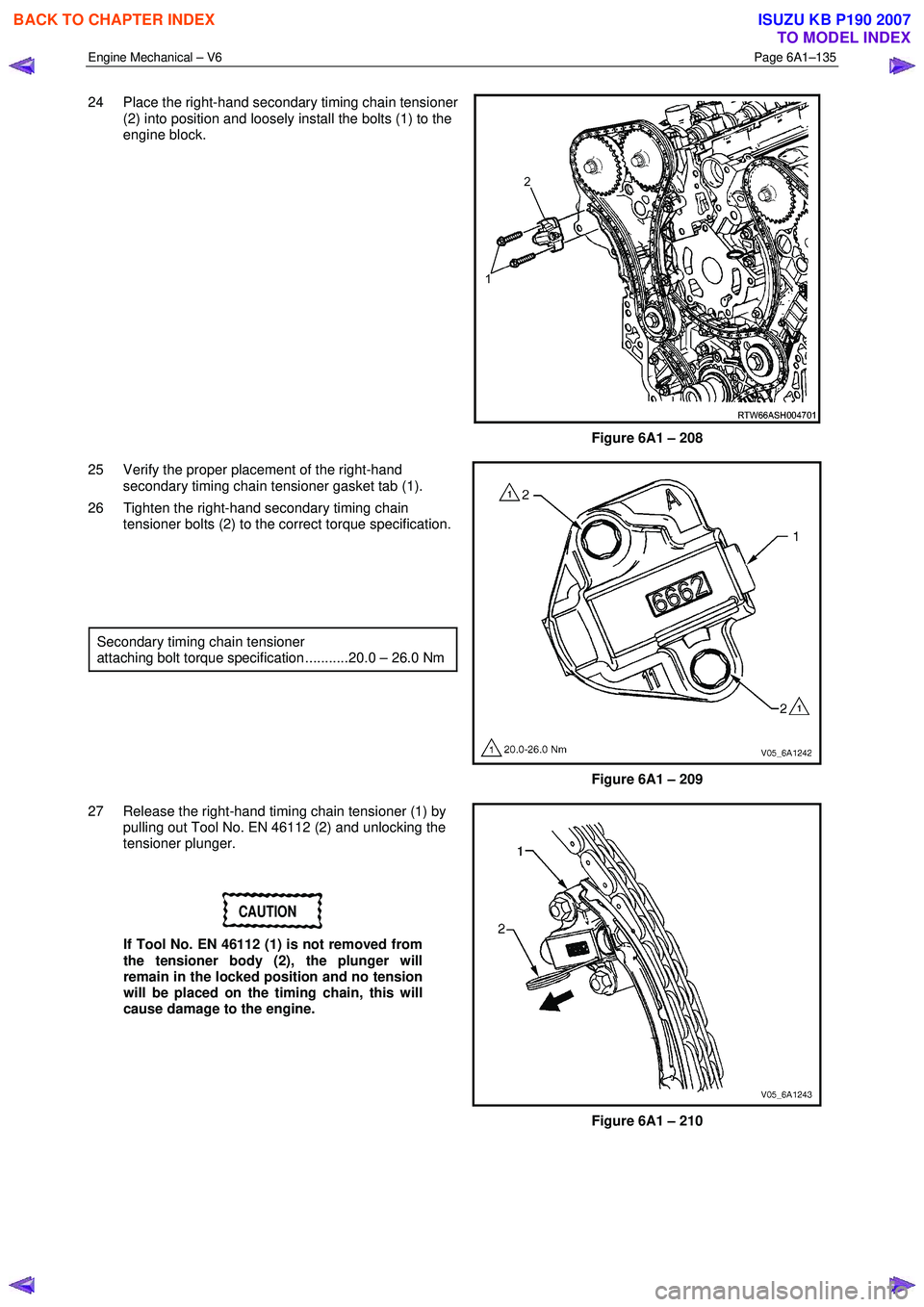
24 Place the right-hand secondary timing chain tensioner
(2) into position and loosely install the bolts (1) to the
engine block.
Figure 6A1 – 208
25 Verify the proper placement of the right-hand secondary timing chain tensioner gasket tab (1).
26 Tighten the right-hand secondary timing chain tensioner bolts (2) to the correct torque specification.
Secondary timing chain tensioner
attaching bolt torque specification ...........20.0 – 26.0 Nm
Figure 6A1 – 209
27 Release the right-hand timing chain tensioner (1) by pulling out Tool No. EN 46112 (2) and unlocking the
tensioner plunger.
CAUTION
If Tool No. EN 46112 (1) is not removed from
the tensioner body (2), the plunger will
remain in the locked position and no tension
will be placed on the timing chain, this will
cause damage to the engine.
Figure 6A1 – 210
BACK TO CHAPTER INDEX
TO MODEL INDEX
ISUZU KB P190 2007
Page 2615 of 6020
Engine Mechanical – V6 Page 6A1–136
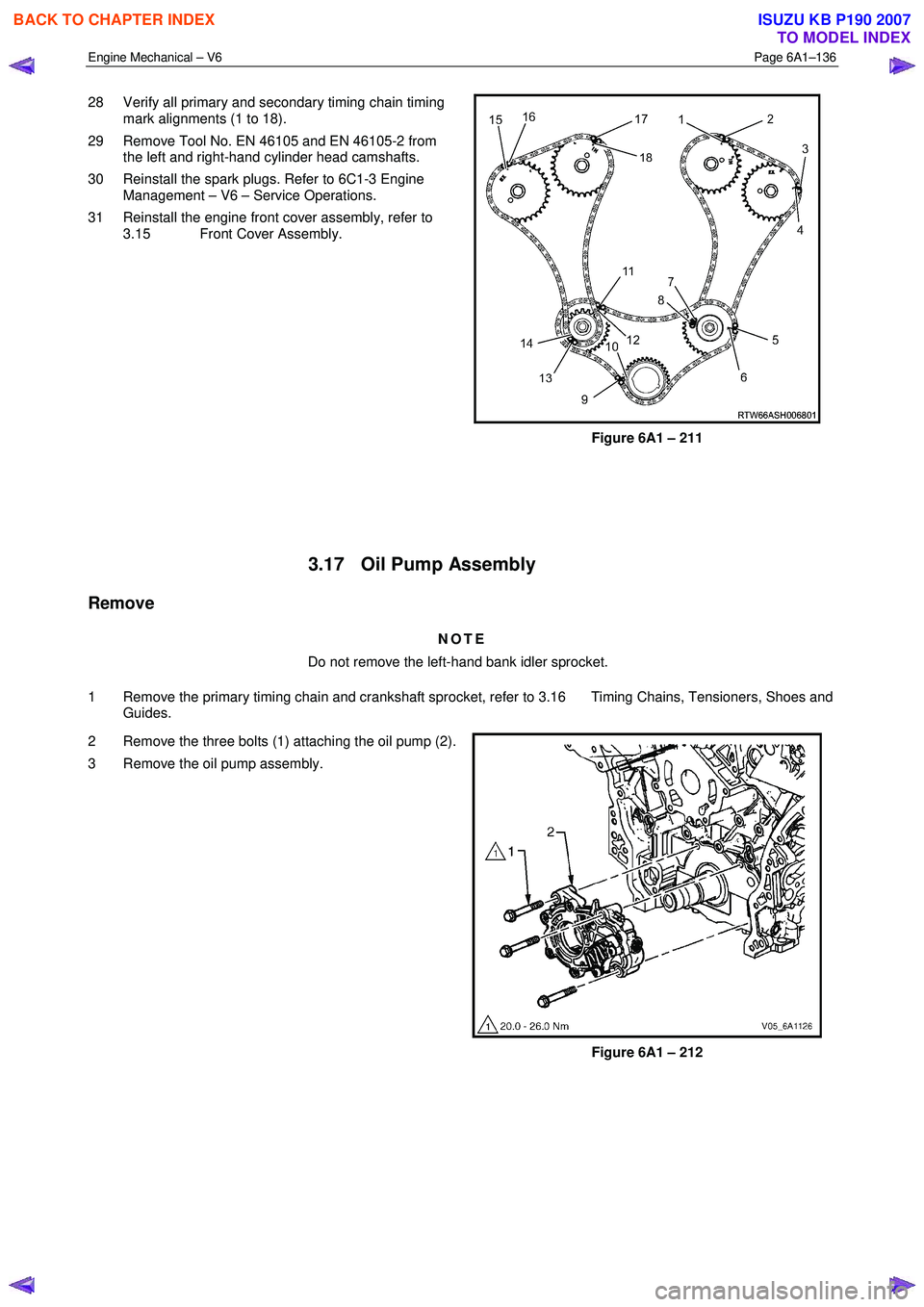
28 Verify all primary and secondary timing chain timing
mark alignments (1 to 18).
29 Remove Tool No. EN 46105 and EN 46105-2 from the left and right-hand cylinder head camshafts.
30 Reinstall the spark plugs. Refer to 6C1-3 Engine Management – V6 – Service Operations.
31 Reinstall the engine front cover assembly, refer to 3.15 Front Cover Assembly.
Figure 6A1 – 211
3.17 Oil Pump Assembly
Remove
NOTE
Do not remove the left-hand bank idler sprocket.
1 Remove the primary timing chain and crankshaft sprocket, refer to 3.16 Timing Chains, Tensioners, Shoes and Guides.
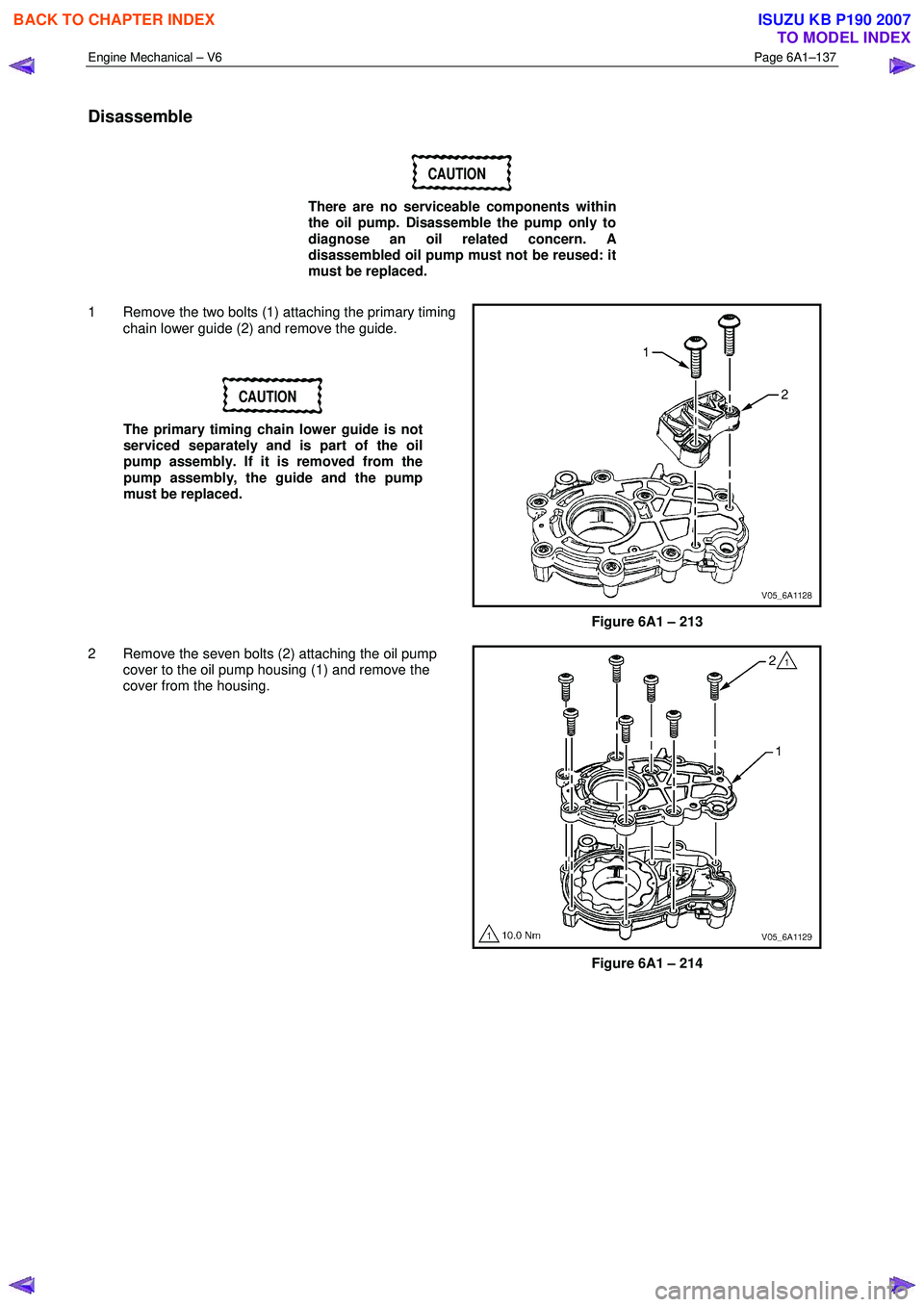
2 Remove the three bolts (1) attaching the oil pump (2).
3 Remove the oil pump assembly.
Figure 6A1 – 212
BACK TO CHAPTER INDEX
TO MODEL INDEX
ISUZU KB P190 2007
Page 2616 of 6020
Engine Mechanical – V6 Page 6A1–137
Disassemble
CAUTION
There are no serviceable components within
the oil pump. Disassemble the pump only to
diagnose an oil related concern. A
disassembled oil pump must not be reused: it
must be replaced.
1 Remove the two bolts (1) attaching the primary timing chain lower guide (2) and remove the guide.
CAUTION
The primary timing chain lower guide is not
serviced separately and is part of the oil
pump assembly. If it is removed from the
pump assembly, the guide and the pump
must be replaced.
Figure 6A1 – 213
2 Remove the seven bolts (2) attaching the oil pump cover to the oil pump housing (1) and remove the
cover from the housing.
Figure 6A1 – 214
BACK TO CHAPTER INDEX
TO MODEL INDEX
ISUZU KB P190 2007
Page 2617 of 6020
Engine Mechanical – V6 Page 6A1–138
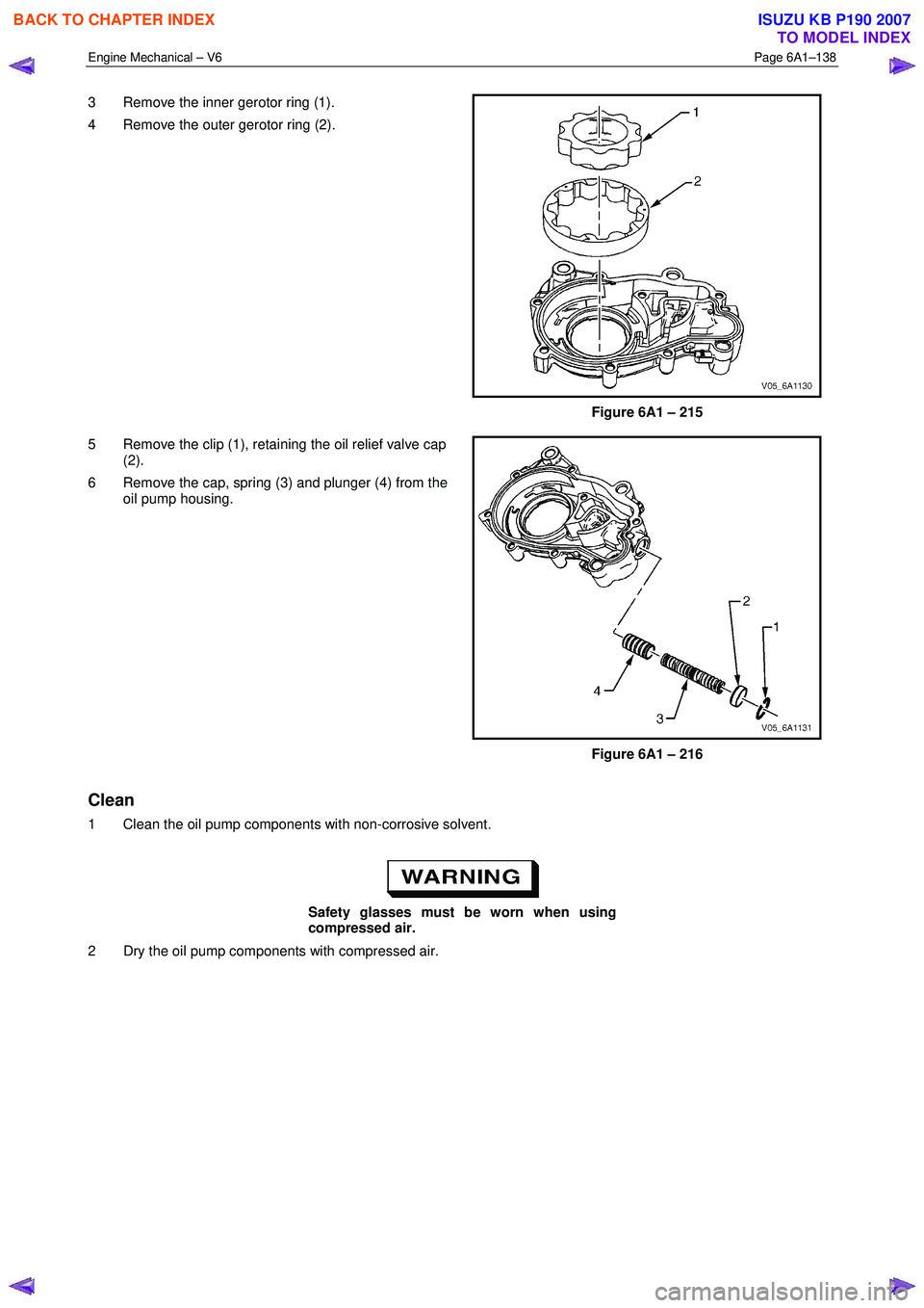
3 Remove the inner gerotor ring (1).
4 Remove the outer gerotor ring (2).
Figure 6A1 – 215
5 Remove the clip (1), retaining the oil relief valve cap (2).
6 Remove the cap, spring (3) and plunger (4) from the oil pump housing.
Figure 6A1 – 216
Clean
1 Clean the oil pump components with non-corrosive solvent.
Safety glasses must be worn when using
compressed air.
2 Dry the oil pump components with compressed air.
BACK TO CHAPTER INDEX
TO MODEL INDEX
ISUZU KB P190 2007
Page 2618 of 6020
Engine Mechanical – V6 Page 6A1–139
Inspect
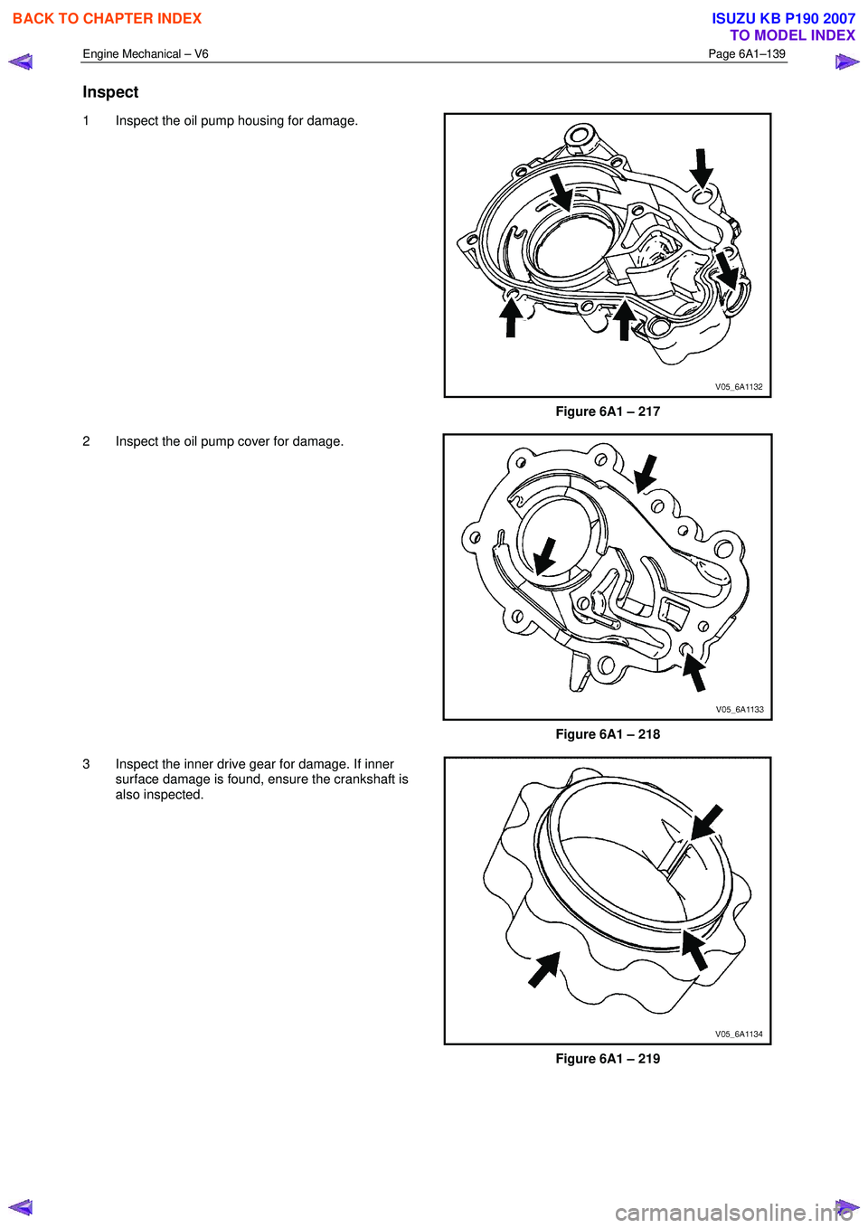
1 Inspect the oil pump housing for damage.
Figure 6A1 – 217
2 Inspect the oil pump cover for damage.
Figure 6A1 – 218
3 Inspect the inner drive gear for damage. If inner surface damage is found, ensure the crankshaft is
also inspected.
Figure 6A1 – 219
BACK TO CHAPTER INDEX
TO MODEL INDEX
ISUZU KB P190 2007
Page 2619 of 6020
Engine Mechanical – V6 Page 6A1–140
4 Inspect the outer driven gear for damage.
Figure 6A1 – 220
5 Inspect the oil pump relief valve components for debris or damage.
Figure 6A1 – 221
6 Inspect the primary camshaft chain lower guide for damage. If replacement of the primary camshaft chain
lower guide is required, replace the entire oil pump
assembly as the primary camshaft chain lower guide
is not serviceable separately.
7 If debris or damage is present within the oil pump, further inspection of all of the engine components is
required.
Figure 6A1 – 222
BACK TO CHAPTER INDEX
TO MODEL INDEX
ISUZU KB P190 2007
Page 2620 of 6020
Engine Mechanical – V6 Page 6A1–141
Reassemble
CAUTION
As there are no serviceable components
within the oil pump, a disassembled oil pump
must be replaced.
Reinstall
1 Align the oil pump gerotor with the crankshaft flats and fit the oil pump assembly to the engine block.
2 Align the pump body (2) with the mounting holes in the cylinder block.
3 Install the oil pump bolt (1), three places, and tighten to the correct torque specification.
4 Install the primary timing chain, refer to 3.16 Timing Chains, Tensioners, Shoes and Guides.
Oil pump attaching bolt torque
specification ............................................20.0 – 26.0 Nm
Figure 6A1 – 223
3.18 Camshaft Sprocket
CAUTION
Setting the camshaft timing is required
whenever the camshaft drive system is
disturbed to ensure the relationship between
any chain and sprocket is not lost. Even when
only one sprocket is involved, multiple
crankshaft rotations will not produce
conditions where correct timing can be
confirmed.
If required, follow the Left-hand Secondary
Camshaft Chain Components reinstallation
procedure to reset the camshaft timing.
Remove
Right-hand Side
1 Remove the right-hand camshaft cover, refer to 3.12 Camshaft Cover.
2 Remove the camshaft position sensors, refer to 6C1-3 Engine Management – Service Operations.
3 Remove the camshaft position actuator solenoids, refer to 6C1-3 Engine Management – V6 – Service Operations.
4 Remove the crankshaft balancer assembly, refer to 3.13 Crankshaft Balancer Assembly.
BACK TO CHAPTER INDEX
TO MODEL INDEX
ISUZU KB P190 2007