ISUZU KB P190 2007 Workshop Repair Manual
Manufacturer: ISUZU, Model Year: 2007, Model line: KB P190, Model: ISUZU KB P190 2007Pages: 6020, PDF Size: 70.23 MB
Page 2661 of 6020
Engine Mechanical – V6 Page 6A1–182
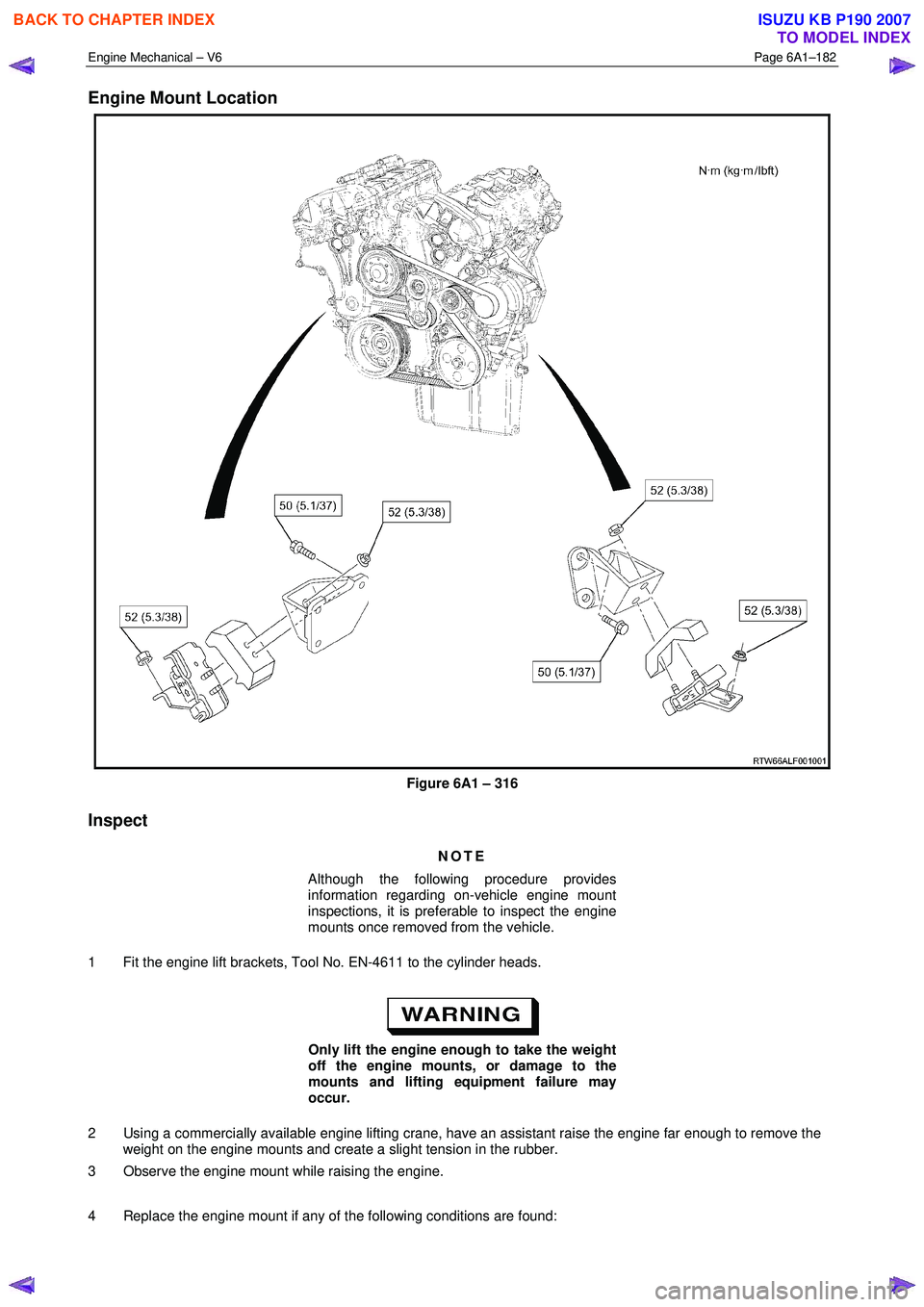
Engine Mount Location
Figure 6A1 – 316
Inspect
NOTE
Although the following procedure provides
information regarding on-vehicle engine mount
inspections, it is preferable to inspect the engine
mounts once removed from the vehicle.
1 Fit the engine lift brackets, Tool No. EN-4611 to the cylinder heads.
Only lift the engine enough to take the weight
off the engine mounts, or damage to the
mounts and lifting equipment failure may
occur.
2 Using a commercially available engine lifting crane, have an assistant raise the engine far enough to remove the weight on the engine mounts and create a slight tension in the rubber.
3 Observe the engine mount while raising the engine.
4 Replace the engine mount if any of the following conditions are found:
BACK TO CHAPTER INDEX
TO MODEL INDEX
ISUZU KB P190 2007
Page 2662 of 6020

Engine Mechanical – V6 Page 6A1–183
• The hard rubber surface is covered with heat check cracks,
• The rubber is split through the centre of the engine mount, or
• The rubber is separated from the metal plate portion of the engine mount.
5 Remove the engine lift brackets, Tool No. EN-46114 from the engine.
Reinstall
The reinstallation procedure for the engine mounts is the reverse of the removal procedure, noting the following:
Ensure all fasteners are tightened to the correct torque specification.
Engine mount bracket to
cylinder block attaching bolt
torque specification
................................................................43.0 – 57.0 Nm
Engine mount to bracket attaching nut
torque specification
................................................................70.0 – 90.0 Nm
Engine mount to frame attaching nut
torque specification
................................................................44.0 – 60.0 Nm
BACK TO CHAPTER INDEX
TO MODEL INDEX
ISUZU KB P190 2007
Page 2663 of 6020
Engine Mechanical – V6 Page 6A1–184
4 Major Service Operations
ATTENTION
The V6 engine is a combination of numerous components, containing machined, honed, polished and lapped
surfaces manufactured on the latest, high technology production equipment. Many of the components
contain tolerances measured in thousandths of a millimetre. Consequently, when any engine component is to
be serviced, care and cleanliness are extremely important.
Prior to re-assembly of the V6 engine, all components must be cleaned and inspected in accordance with the
relevant procedures throughout this section, and replaced or repaired where required.
In addition to cleaning and inspecting components, a liberal coating of engine oil should be applied to friction
surfaces during assembly to protect and lubricate the surfaces on initial operation.
When performing any service operation contained in this Section, it should be understood that correct
cleaning and protection of machined surfaces and friction areas is part of the repair procedure. This is
considered standard workshop practice, even if not specifically stated. Torque values must be used as
specified during reassembly to ensure correct retention of all components.
Through out this section, fastener torque wrench specifications may be accompanied with the following
identification marks:
■ Fasteners must be replaced after loosening.
Fasteners either have micro encapsulated sealant applied or incorporate a mechanical thread lock and
should only be re-used once. If in doubt, replacement is recommended.
If one of these identification marks is present alongside a fastener torque wrench specification, the
recommendation regarding that fastener must be adhered to.
4.1 Engine Removal
CAUTION
• Allow the engine to cool to at least 50 °
°°
°
C,
before attempting fastener removal.
• As aluminium has a greater rate of thermal
expansion than that of cast iron,
aluminium bolt hole threads will change
dimension to a larger extent than cast iron
bolt threads.
• If a bolt or other threaded component is
removed before the engine is allowed to
cool to at least 50 °
°°
°
C, threads could be
pulled from the cylinder block or cylinder
head.
• Do not use impact tools to remove bolts
during engine disassembly. While this may
be common practice with cast iron engine
components, use of these tools is likely to
pull the aluminium threads in the cylinder
block or head of this engine.
BACK TO CHAPTER INDEX
TO MODEL INDEX
ISUZU KB P190 2007
Page 2664 of 6020
Engine Mechanical – V6 Page 6A1–185
Remove
1 Remove the skid plate.
2 Drain the radiator coolant, refer to 6B1 Engine Cooling – V6.
3 Disconnect the battery negative and positive terminal, refer to 8A Electrical Body & Chassis.
4 Remove the battery from the vehicle.
5 Depressurise the fuel system pressure, refer to 6C Fuel System – V6.
6 Make alignment marks on the bonnet and hinges in order to return the bonnet to the exact original position.
7 Remove the bonnet, refer to 2B Sheet Metal.
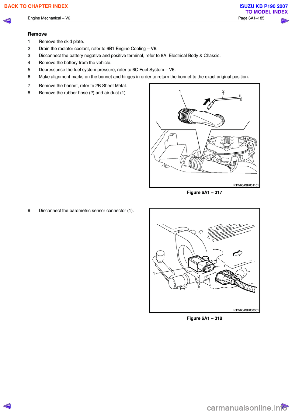
8 Remove the rubber hose (2) and air duct (1).
Figure 6A1 – 317
9 Disconnect the barometric sensor connector (1).
Figure 6A1 – 318
BACK TO CHAPTER INDEX
TO MODEL INDEX
ISUZU KB P190 2007
Page 2665 of 6020
Engine Mechanical – V6 Page 6A1–186
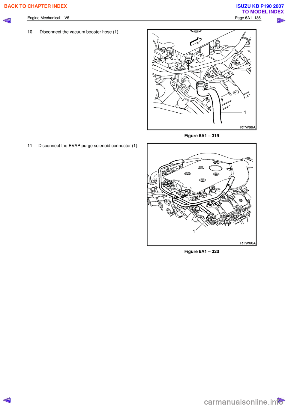
10 Disconnect the vacuum booster hose (1).
Figure 6A1 – 319
11 Disconnect the EVAP purge solenoid connector (1).
Figure 6A1 – 320
BACK TO CHAPTER INDEX
TO MODEL INDEX
ISUZU KB P190 2007
Page 2666 of 6020
Engine Mechanical – V6 Page 6A1–187
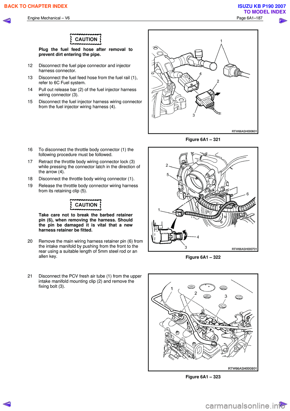
Plug the fuel feed hose after removal to
prevent dirt entering the pipe.
12 Disconnect the fuel pipe connector and injector harness connector.
13 Disconnect the fuel feed hose from the fuel rail (1), refer to 6C Fuel system.
14 Pull out release bar (2) of the fuel injector harness wiring connector (3).
15 Disconnect the fuel injector harness wiring connector from the fuel injector wiring harness (4).
Figure 6A1 – 321
16 To disconnect the throttle body connector (1) the following procedure must be followed.
17 Retract the throttle body wiring connector lock (3) while pressing the connector latch in the direction of
the arrow (4).
18 Disconnect the throttle body wiring connector (1).
19 Release the throttle body connector wiring harness from its retaining clip (5).
Take care not to break the barbed retainer
pin (6), when removing the harness. Should
the pin be damaged it is vital that a new
harness retainer be fitted.
20 Remove the main wiring harness retainer pin (6) from the intake manifold by pushing from the front to the
rear using a suitable length of 5mm steel rod or an
allen key.
Figure 6A1 – 322
21 Disconnect the PCV fresh air tube (1) from the upper intake manifold mounting clip (2) and remove the
fixing bolt (3).
Figure 6A1 – 323
BACK TO CHAPTER INDEX
TO MODEL INDEX
ISUZU KB P190 2007
Page 2667 of 6020
Engine Mechanical – V6 Page 6A1–188
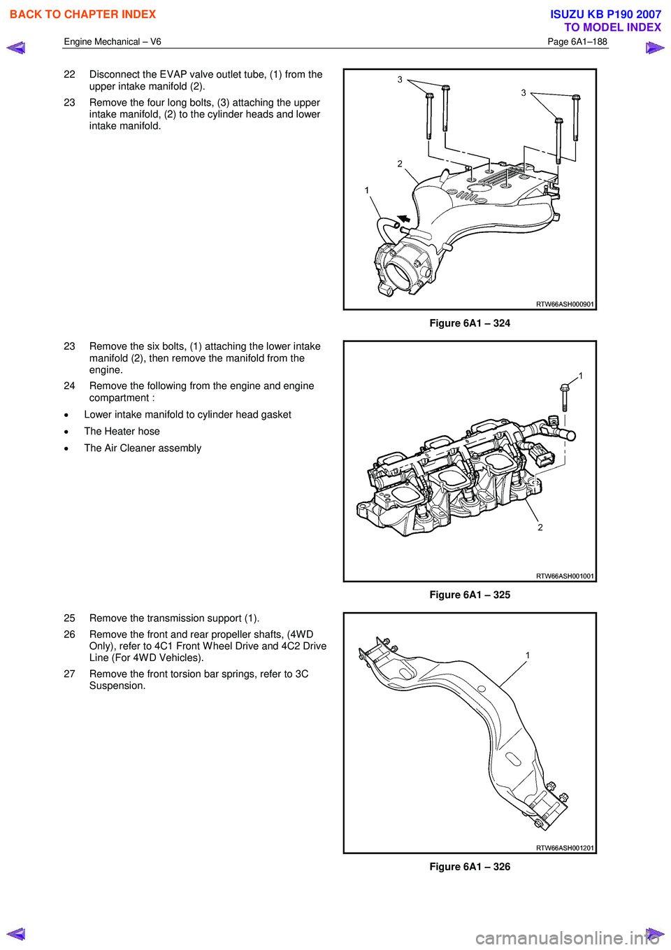
22 Disconnect the EVAP valve outlet tube, (1) from the
upper intake manifold (2).
23 Remove the four long bolts, (3) attaching the upper intake manifold, (2) to the cylinder heads and lower
intake manifold.
Figure 6A1 – 324
23 Remove the six bolts, (1) attaching the lower intake manifold (2), then remove the manifold from the
engine.
24 Remove the following from the engine and engine compartment :
• Lower intake manifold to cylinder head gasket
• The Heater hose
• The Air Cleaner assembly
Figure 6A1 – 325
25 Remove the transmission support (1).
26 Remove the front and rear propeller shafts, (4W D Only), refer to 4C1 Front W heel Drive and 4C2 Drive
Line (For 4W D Vehicles).
27 Remove the front torsion bar springs, refer to 3C Suspension.
Figure 6A1 – 326
BACK TO CHAPTER INDEX
TO MODEL INDEX
ISUZU KB P190 2007
Page 2668 of 6020
Engine Mechanical – V6 Page 6A1–189
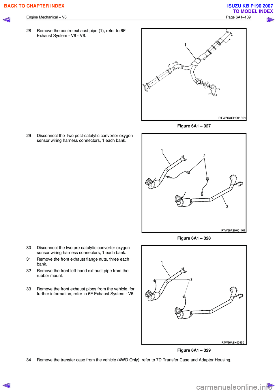
28 Remove the centre exhaust pipe (1), refer to 6F
Exhaust System - V6 - V6.
Figure 6A1 – 327
29 Disconnect the two post-catalytic converter oxygen sensor wiring harness connectors, 1 each bank.
Figure 6A1 – 328
30 Disconnect the two pre-catalytic converter oxygen sensor wiring harness connectors, 1 each bank.
31 Remove the front exhaust flange nuts, three each bank.
32 Remove the front left-hand exhaust pipe from the rubber mount.
33 Remove the front exhaust pipes from the vehicle, for further information, refer to 6F Exhaust System - V6.
Figure 6A1 – 329
34 Remove the transfer case from the vehicle (4W D Only), refer to 7D Transfer Case and Adaptor Housing.
BACK TO CHAPTER INDEX
TO MODEL INDEX
ISUZU KB P190 2007
Page 2669 of 6020
Engine Mechanical – V6 Page 6A1–190
35 Disconnect the harness connector from the transmission, refer to 7B1 Manual Transmission – V6 or 7C1, 2, 3 or 4
for automatic transmission.
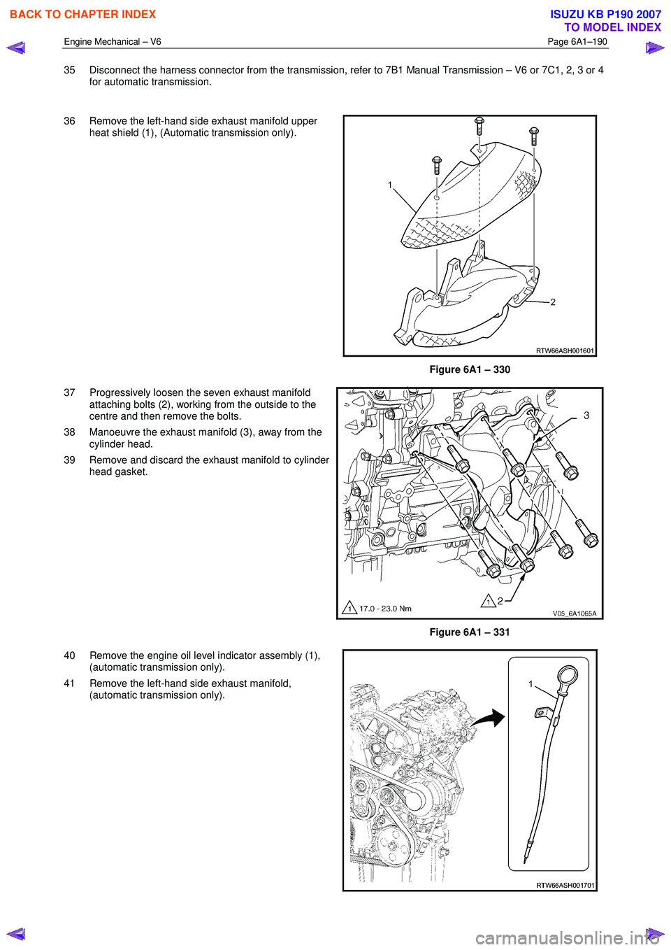
36 Remove the left-hand side exhaust manifold upper heat shield (1), (Automatic transmission only).
Figure 6A1 – 330
37 Progressively loosen the seven exhaust manifold attaching bolts (2), working from the outside to the
centre and then remove the bolts.
38 Manoeuvre the exhaust manifold (3), away from the cylinder head.
39 Remove and discard the exhaust manifold to cylinder head gasket.
Figure 6A1 – 331
40 Remove the engine oil level indicator assembly (1), (automatic transmission only).
41 Remove the left-hand side exhaust manifold, (automatic transmission only).
BACK TO CHAPTER INDEX
TO MODEL INDEX
ISUZU KB P190 2007
Page 2670 of 6020

Engine Mechanical – V6 Page 6A1–191
Figure 6A1 – 332
Figure 6A1 – 333 Figure 6A1 – 334
42 Fit the engine lifting brackets (1), (EN–46114) and attach the engine hoist, raise the engine to take the weight off the engine mounts.
Engine Lift Bracket Attaching Bolt
torque specification
.............................................................58.0 – 72.0.0 Nm
43 Remove the left-hand side knock sensor (1).
Figure 6A1 – 335
NOTE
Removal or the starter motor is only required for
vehicles with an Automatic Transmission.
BACK TO CHAPTER INDEX
TO MODEL INDEX
ISUZU KB P190 2007