ISUZU KB P190 2007 Workshop Repair Manual
Manufacturer: ISUZU, Model Year: 2007, Model line: KB P190, Model: ISUZU KB P190 2007Pages: 6020, PDF Size: 70.23 MB
Page 2651 of 6020
Engine Mechanical – V6 Page 6A1–172
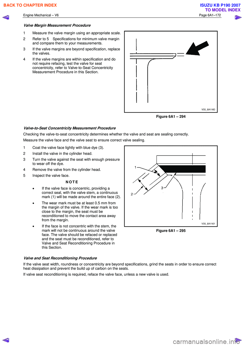
Valve Margin Measurement Procedure
1 Measure the valve margin using an appropriate scale.
2 Refer to 5 Specifications for minimum valve margin and compare them to your measurements.
3 If the valve margins are beyond specification, replace the valves.
4 If the valve margins are within specification and do not require refacing, test the valve for seat
concentricity, refer to Valve-to-Seat Concentricity
Measurement Procedure in this Section.
Figure 6A1 – 294
Valve-to-Seat Concentricity Measurement Procedure
Checking the valve-to-seat concentricity determines whether the valve and seat are sealing correctly.
Measure the valve face and the valve seat to ensure correct valve sealing.
1 Coat the valve face lightly with blue dye (3).
2 Install the valve in the cylinder head.
3 Turn the valve against the seat with enough pressure to wear off the dye.
4 Remove the valve from the cylinder head.
5 Inspect the valve face.
NOTE
• If the valve face is concentric, providing a
correct seal, with the valve stem, a continuous
mark (1) will be made around the entire face (2).
• The wear mark must be at least 0.5 mm from
the margin of the valve. If the wear mark is too
close to the margin, the seat must be
reconditioned to move the contact area away
from the margin.
• If the face is not concentric with the stem, the
mark will not be continuous around the valve
face. The valve should be refaced or replaced
and the seat must be reconditioned, refer to
Valve and Seat Reconditioning Procedure in
this Section.
Figure 6A1 – 295
Valve and Seat Reconditioning Procedure
If the valve seat width, roundness or concentricity are beyond specifications, grind the seats in order to ensure correct
heat dissipation and prevent the build up of carbon on the seats.
If valve seat reconditioning is required, reface the valve face, unless a new valve is used.
BACK TO CHAPTER INDEX
TO MODEL INDEX
ISUZU KB P190 2007
Page 2652 of 6020

Engine Mechanical – V6 Page 6A1–173
1 Grind the valve seats (2) to the correct angle
specification, refer to 5 Specifications.
2 Using the correct angle specification, grind and relieve the valve seats (1) to correctly position the
valve seating surface (2) to the valve.
3 Using the correct angle specification, grind and undercut the valve seats (3) to narrow the valve seat
widths to the specifications, refer to 5 Specifications.
4 If the original valve is being used, grind the valve to the specifications, refer to 5 Specifications.
Measure the valve margin again after grinding, refer
to Valve Margin Measurement Procedure in this
Section. Replace the valve if the margin is out of
specification. New valves do not require grinding.
5 W hen grinding the valves and seats, grind off as little material as possible. Cutting valve seat results in
lowering the valve spring pressure.
6 Install the valve in the cylinder head.
Figure 6A1 – 296
CAUTION
If using refaced valves, lap the valves into the
seats with a fine grinding compound. The
refacing and reseating operations should
leave the refinished surfaces smooth and true
so that minimal lapping is required. Excessive
lapping will groove the valve face and prevent
a good seat when hot.
NOTE
• Clean any remaining lapping compound from
the valve and seat with solvent and
compressed air prior to final assembly.
• If fitting new valves, do not lap the valves
under any condition.
7 After obtaining the correct valve seat width in the cylinder head, measure the valve stem height, refer to Valve Stem Height Measurement Procedure in this Section.
8 If the valve stem height is acceptable, test the seats for concentricity, refer to Valve-to-Seat Concentricity Measurement Procedure in this Section.
BACK TO CHAPTER INDEX
TO MODEL INDEX
ISUZU KB P190 2007
Page 2653 of 6020

Engine Mechanical – V6 Page 6A1–174
Valve Stem Height Measurement Procedure
CAUTION
To determine the valve stem height
measurement, measure from the valve
spring seat to the valve spring retainer.
1 Install the valve into the valve guide.
2 Ensure the valve is seated to the valve seat.
3 Install the valve stem oil seal.
4 Install the valve spring retainer and valve stem keys.
5 Measure the distance (1) between the cylinder head to the bottom of the valve spring retainer, refer to 5
Specifications.
6 If the maximum height specification is exceeded, a new valve should be installed and the valve stem
height re-measured.
Figure 6A1 – 297
CAUTION
Do not grind the valve stem tip. The tip of the
valve is hardened and grinding the tip will
eliminate the hardened surface causing
premature wear and possible engine damage.
CAUTION
Do not use shims to adjust valve stem height.
The use of shims will cause the valve spring
to bottom out before the camshaft lobe is at
peak lift and engine damage could result.
7 If the valve stem height still exceeds the maximum height specification, the cylinder head must be replaced.
Assemble
1 Install the cylinder head coolant threaded plugs (1) and tighten to the correct torque specification.
Cylinder head threaded plug ..............................31.0 Nm
Figure 6A1 – 298
BACK TO CHAPTER INDEX
TO MODEL INDEX
ISUZU KB P190 2007
Page 2654 of 6020
Engine Mechanical – V6 Page 6A1–175
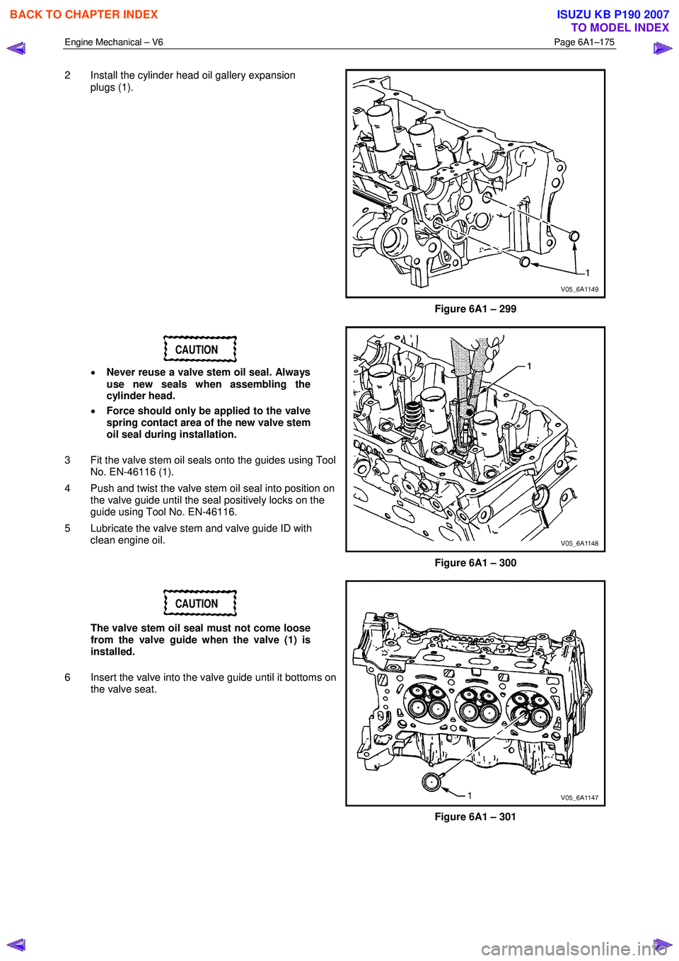
2 Install the cylinder head oil gallery expansion
plugs (1).
Figure 6A1 – 299
CAUTION
• Never reuse a valve stem oil seal. Always
use new seals when assembling the
cylinder head.
• Force should only be applied to the valve
spring contact area of the new valve stem
oil seal during installation.
3 Fit the valve stem oil seals onto the guides using Tool No. EN-46116 (1).
4 Push and twist the valve stem oil seal into position on the valve guide until the seal positively locks on the
guide using Tool No. EN-46116.
5 Lubricate the valve stem and valve guide ID with clean engine oil.
Figure 6A1 – 300
CAUTION
The valve stem oil seal must not come loose
from the valve guide when the valve (1) is
installed.
6 Insert the valve into the valve guide until it bottoms on the valve seat.
Figure 6A1 – 301
BACK TO CHAPTER INDEX
TO MODEL INDEX
ISUZU KB P190 2007
Page 2655 of 6020
Engine Mechanical – V6 Page 6A1–176
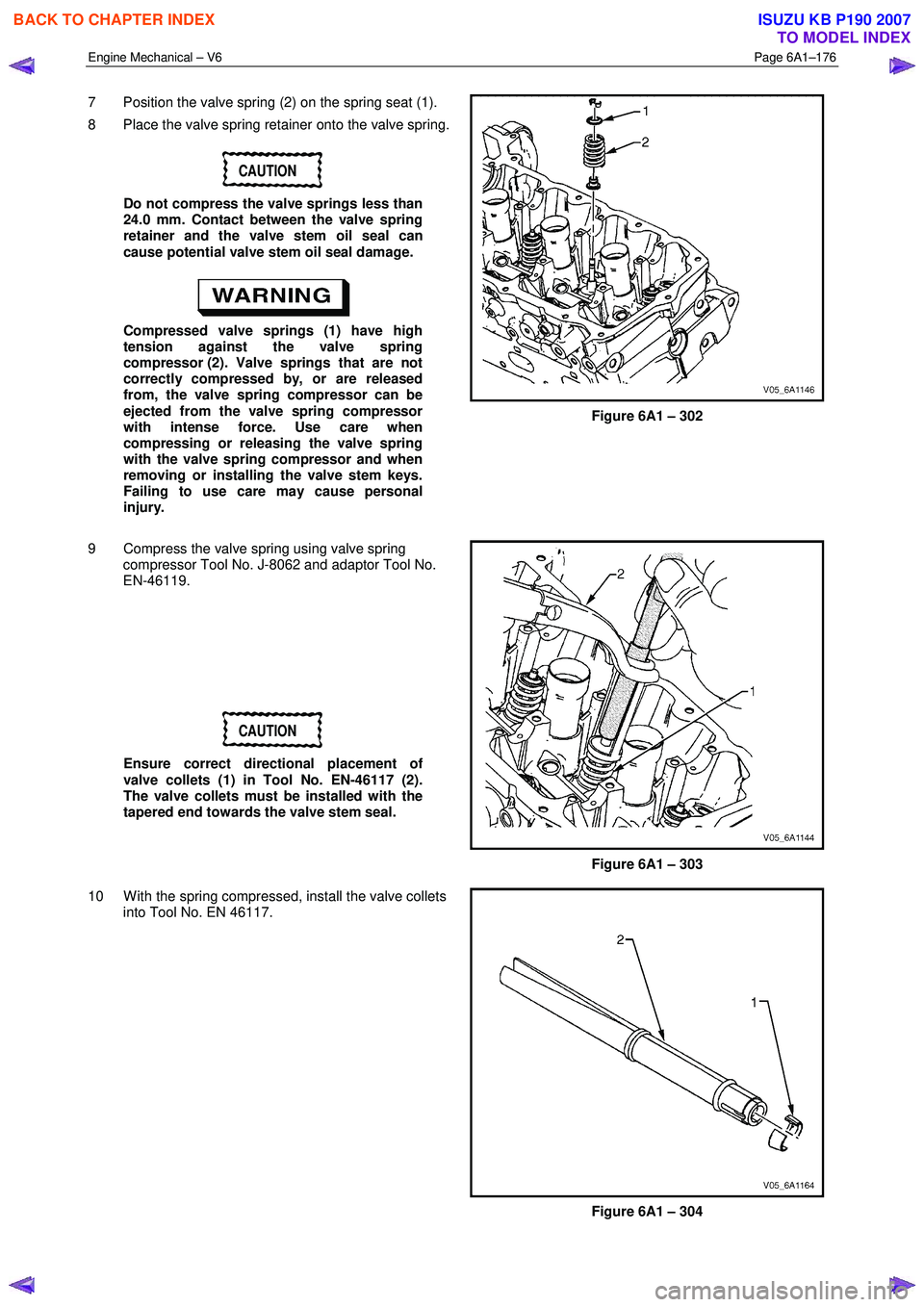
7 Position the valve spring (2) on the spring seat (1).
8 Place the valve spring retainer onto the valve spring.
CAUTION
Do not compress the valve springs less than
24.0 mm. Contact between the valve spring
retainer and the valve stem oil seal can
cause potential valve stem oil seal damage.
Compressed valve springs (1) have high
tension against the valve spring
compressor (2). Valve springs that are not
correctly compressed by, or are released
from, the valve spring compressor can be
ejected from the valve spring compressor
with intense force. Use care when
compressing or releasing the valve spring
with the valve spring compressor and when
removing or installing the valve stem keys.
Failing to use care may cause personal
injury.
Figure 6A1 – 302
9 Compress the valve spring using valve spring compressor Tool No. J-8062 and adaptor Tool No.
EN-46119.
CAUTION
Ensure correct directional placement of
valve collets (1) in Tool No. EN-46117 (2).
The valve collets must be installed with the
tapered end towards the valve stem seal.
Figure 6A1 – 303
10 W ith the spring compressed, install the valve collets into Tool No. EN 46117.
Figure 6A1 – 304
BACK TO CHAPTER INDEX
TO MODEL INDEX
ISUZU KB P190 2007
Page 2656 of 6020
Engine Mechanical – V6 Page 6A1–177
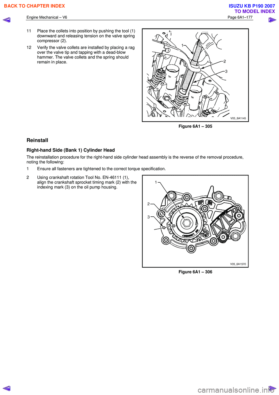
11 Place the collets into position by pushing the tool (1)
downward and releasing tension on the valve spring
compressor (2).
12 Verify the valve collets are installed by placing a rag over the valve tip and tapping with a dead-blow
hammer. The valve collets and the spring should
remain in place.
Figure 6A1 – 305
Reinstall
Right-hand Side (Bank 1) Cylinder Head
The reinstallation procedure for the right-hand side cylinder head assembly is the reverse of the removal procedure,
noting the following:
1 Ensure all fasteners are tightened to the correct torque specification.
2 Using crankshaft rotation Tool No. EN-46111 (1), align the crankshaft sprocket timing mark (2) with the
indexing mark (3) on the oil pump housing.
Figure 6A1 – 306
BACK TO CHAPTER INDEX
TO MODEL INDEX
ISUZU KB P190 2007
Page 2657 of 6020
Engine Mechanical – V6 Page 6A1–178
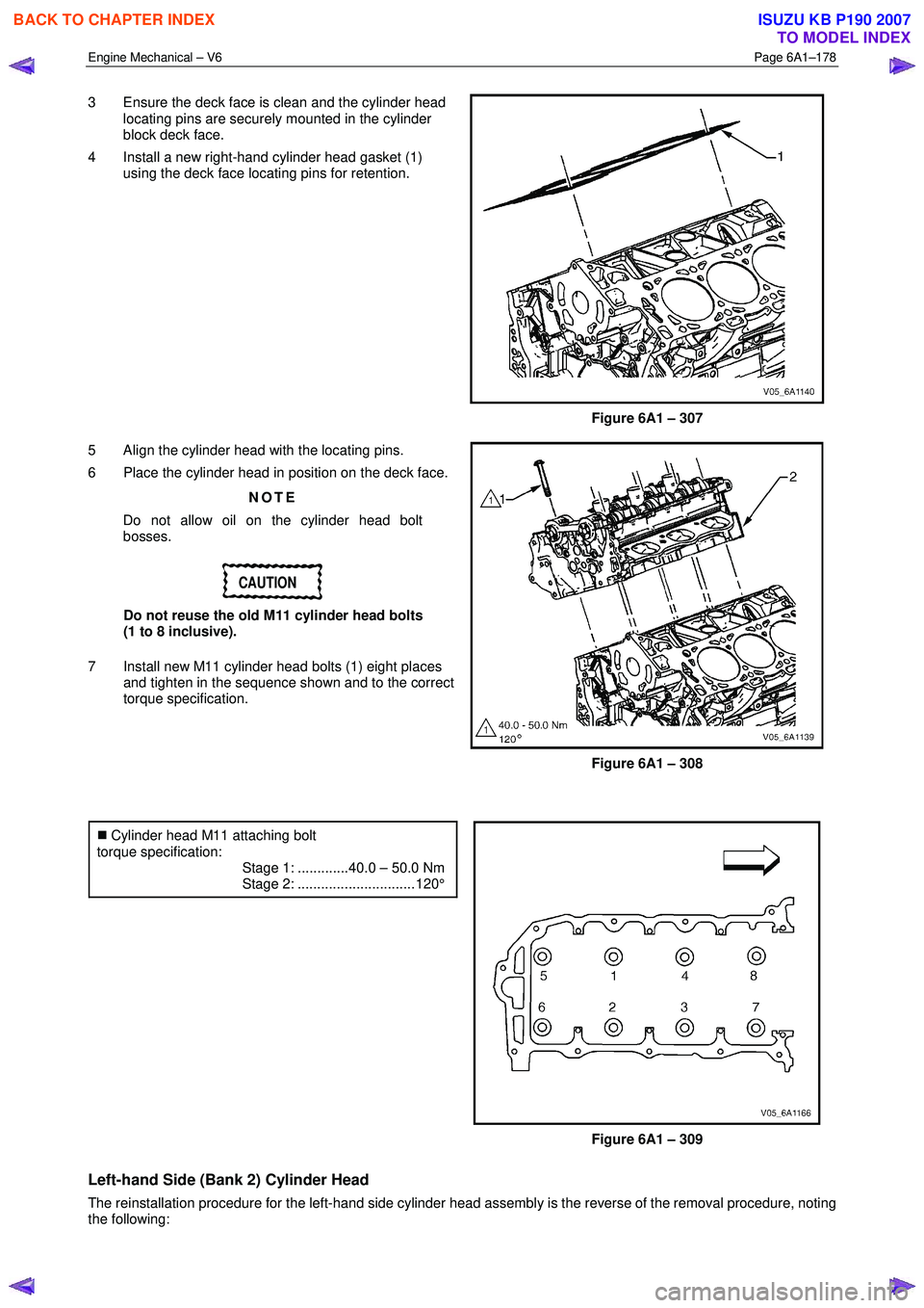
3 Ensure the deck face is clean and the cylinder head
locating pins are securely mounted in the cylinder
block deck face.
4 Install a new right-hand cylinder head gasket (1) using the deck face locating pins for retention.
Figure 6A1 – 307
5 Align the cylinder head with the locating pins.
6 Place the cylinder head in position on the deck face.
NOTE
Do not allow oil on the cylinder head bolt
bosses.
CAUTION
Do not reuse the old M11 cylinder head bolts
(1 to 8 inclusive).
7 Install new M11 cylinder head bolts (1) eight places and tighten in the sequence shown and to the correct
torque specification.
Figure 6A1 – 308
�„ Cylinder head M11 attaching bolt
torque specification:
Stage 1: .............40.0 – 50.0 Nm
Stage 2: .............................. 120°
Figure 6A1 – 309
Left-hand Side (Bank 2) Cylinder Head
The reinstallation procedure for the left-hand side cylinder head assembly is the reverse of the removal procedure, noting
the following:
BACK TO CHAPTER INDEX
TO MODEL INDEX
ISUZU KB P190 2007
Page 2658 of 6020
Engine Mechanical – V6 Page 6A1–179
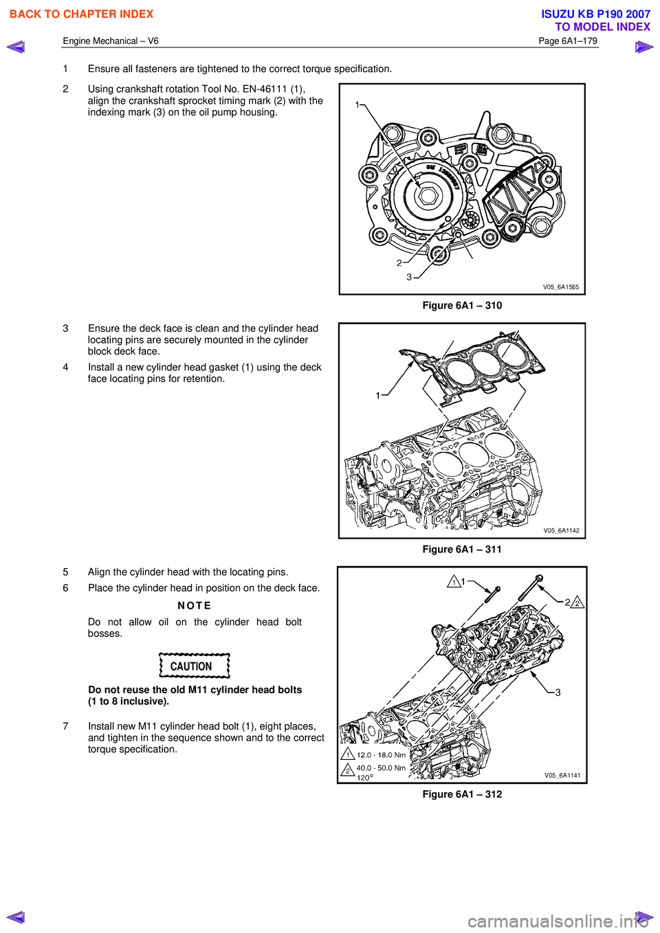
1 Ensure all fasteners are tightened to the correct torque specification.
2 Using crankshaft rotation Tool No. EN-46111 (1), align the crankshaft sprocket timing mark (2) with the
indexing mark (3) on the oil pump housing.
Figure 6A1 – 310
3 Ensure the deck face is clean and the cylinder head locating pins are securely mounted in the cylinder
block deck face.
4 Install a new cylinder head gasket (1) using the deck face locating pins for retention.
Figure 6A1 – 311
5 Align the cylinder head with the locating pins.
6 Place the cylinder head in position on the deck face.
NOTE
Do not allow oil on the cylinder head bolt
bosses.
CAUTION
Do not reuse the old M11 cylinder head bolts
(1 to 8 inclusive).
7 Install new M11 cylinder head bolt (1), eight places, and tighten in the sequence shown and to the correct
torque specification.
Figure 6A1 – 312
BACK TO CHAPTER INDEX
TO MODEL INDEX
ISUZU KB P190 2007
Page 2659 of 6020
Engine Mechanical – V6 Page 6A1–180
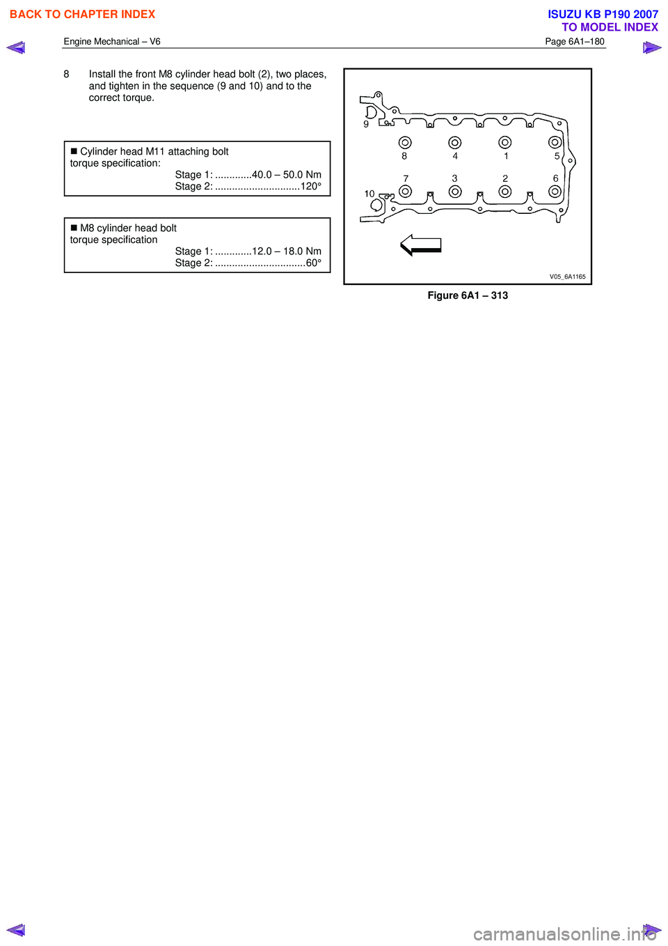
8 Install the front M8 cylinder head bolt (2), two places,
and tighten in the sequence (9 and 10) and to the
correct torque.
�„ Cylinder head M11 attaching bolt
torque specification:
Stage 1: .............40.0 – 50.0 Nm
Stage 2: .............................. 120°
�„ M8 cylinder head bolt
torque specification
Stage 1: .............12.0 – 18.0 Nm
Stage 2: ................................ 60°
Figure 6A1 – 313
BACK TO CHAPTER INDEX
TO MODEL INDEX
ISUZU KB P190 2007
Page 2660 of 6020
Engine Mechanical – V6 Page 6A1–181
3.23 Engine Mounts and Brackets
Remove
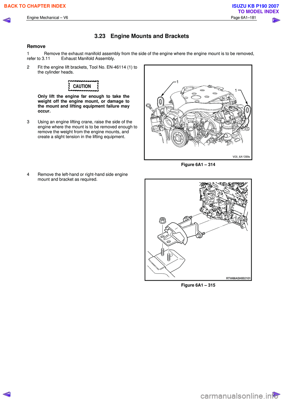
1 Remove the exhaust manifold assembly from the side of the engine where the engine mount is to be removed,
refer to 3.11 Exhaust Manifold Assembly.
2 Fit the engine lift brackets, Tool No. EN-46114 (1) to the cylinder heads.
CAUTION
Only lift the engine far enough to take the
weight off the engine mount, or damage to
the mount and lifting equipment failure may
occur.
3 Using an engine lifting crane, raise the side of the engine where the mount is to be removed enough to
remove the weight from the engine mounts, and
create a slight tension in the lifting equipment.
Figure 6A1 – 314
4 Remove the left-hand or right-hand side engine mount and bracket as required.
Figure 6A1 – 315
BACK TO CHAPTER INDEX
TO MODEL INDEX
ISUZU KB P190 2007