ISUZU KB P190 2007 Workshop Repair Manual
KB P190 2007
ISUZU
ISUZU
https://www.carmanualsonline.info/img/61/57177/w960_57177-0.png
ISUZU KB P190 2007 Workshop Repair Manual
Trending: open bonnet, tailgate, adding oil, fuel pump, charging, maintenance schedule, service indicator
Page 4141 of 6020
7A4–6 UNIT REPAIR (AW30–40LE)
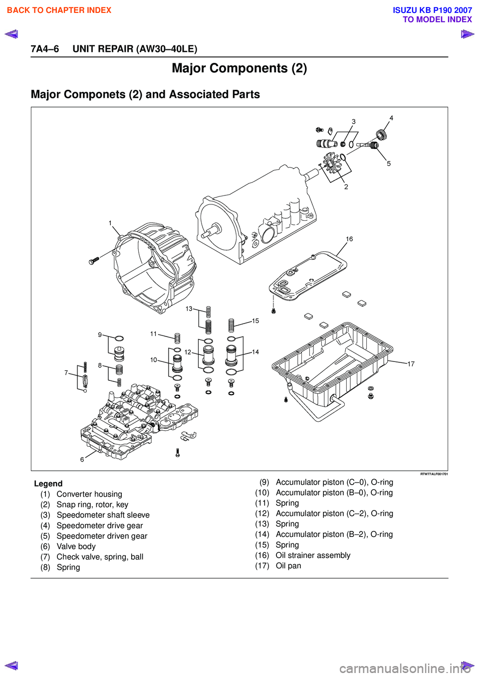
Major Components (2)
Major Componets (2) and Associated Parts
RTW77ALF001701
EndOFCallout
Legend(1) Converter housing
(2) Snap ring, rotor, key
(3) Speedometer shaft sleeve
(4) Speedometer drive gear
(5) Speedometer driven gear
(6) Valve body
(7) Check valve, spring, ball
(8) Spring (9) Accumulator piston (C
–0), O-ring
(10) Accumulator piston (B –0), O-ring
(11) Spring
(12) Accumulator piston (C –2), O-ring
(13) Spring
(14) Accumulator piston (B –2), O-ring
(15) Spring
(16) Oil strainer assembly
(17) Oil pan
BACK TO CHAPTER INDEX
TO MODEL INDEX
ISUZU KB P190 2007
Page 4142 of 6020
UNIT REPAIR (AW30–40LE) 7A4–7
Disassembly
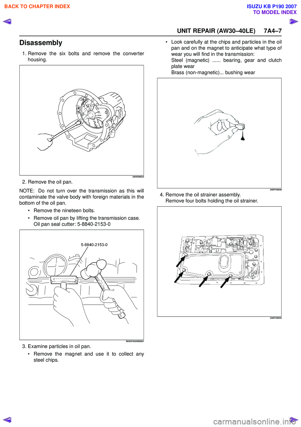
1. Remove the six bolts and remove the converterhousing.
240R200022
2. Remove the oil pan.
NOTE: Do not turn over the transmission as this will
contaminate the valve body with foreign materials in the
bottom of the oil pan.
Remove the nineteen bolts.
Remove oil pan by lifting the transmission case.
Oil pan seal cutter: 5-8840-2153-0
RUW37ASH002901
3. Examine particles in oil pan.
Remove the magnet and use it to collect any
steel chips.
Look carefully at the chips and particles in the oil
pan and on the magnet to anticipate what type of
wear you will find in the transmission:
Steel (magnetic) ...... bearing, gear and clutch
plate wear
Brass (non-magnetic)... bushing wear
240RY00008
4. Remove the oil strainer assembly. Remove four bolts holding the oil strainer.
244RY00003
BACK TO CHAPTER INDEX
TO MODEL INDEX
ISUZU KB P190 2007
Page 4143 of 6020
7A4–8 UNIT REPAIR (AW30–40LE)
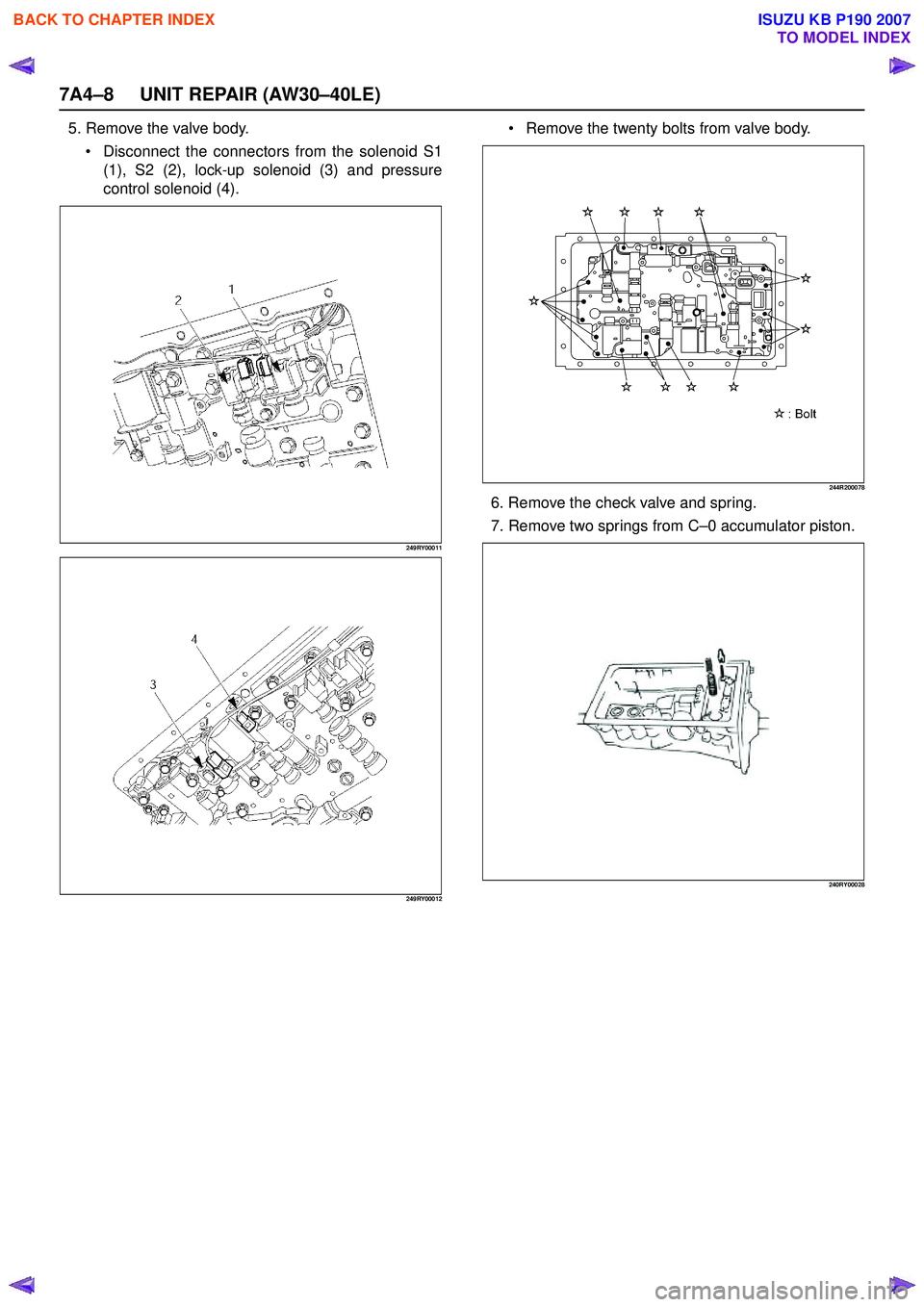
5. Remove the valve body. Disconnect the connectors from the solenoid S1
(1), S2 (2), lock-up solenoid (3) and pressure
control solenoid (4).
249RY00011
249RY00012
Remove the twenty bolts from valve body.
244R200078
6. Remove the check valve and spring.
7. Remove two springs from C –0 accumulator piston.
240RY00028
BACK TO CHAPTER INDEX
TO MODEL INDEX
ISUZU KB P190 2007
Page 4144 of 6020
UNIT REPAIR (AW30–40LE) 7A4–9
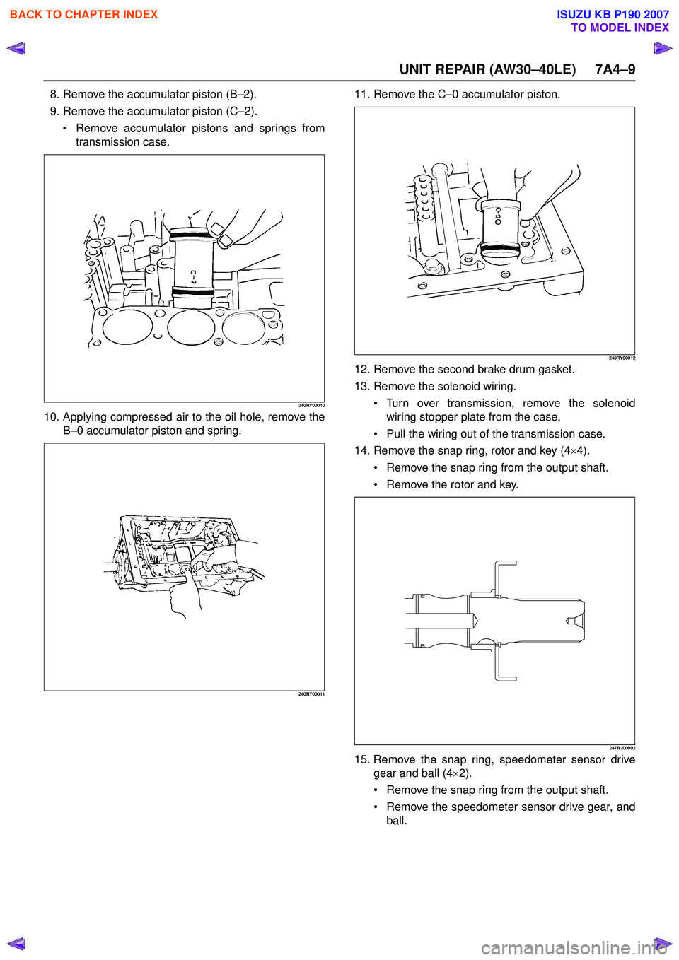
8. Remove the accumulator piston (B–2).
9. Remove the accumulator piston (C –2).
Remove accumulator pistons and springs from
transmission case.
240RY00010
10. Applying compressed air to the oil hole, remove the B–0 accumulator piston and spring.
240RY00011
11. Remove the C –0 accumulator piston.
240RY00012
12. Remove the second brake drum gasket.
13. Remove the solenoid wiring.
Turn over transmission, remove the solenoid
wiring stopper plate from the case.
Pull the wiring out of the transmission case.
14. Remove the snap ring, rotor and key (4 ×4).
Remove the snap ring from the output shaft.
Remove the rotor and key.
247R200002
15. Remove the snap ring, speedometer sensor drive
gear and ball (4 ×2).
Remove the snap ring from the output shaft.
Remove the speedometer sensor drive gear, and
ball.
BACK TO CHAPTER INDEX
TO MODEL INDEX
ISUZU KB P190 2007
Page 4145 of 6020
7A4–10 UNIT REPAIR (AW30–40LE)
16. Remove the spacer, rotor, key and snap ring (4×2).
Remove the spacer, rotor and key.
Remove the snap ring from the output shaft.
247L100001
Reassembly
1. Install the converter housing.
Torque:
M10 – 34 N ·m (3.5 kgf ·m/25 lb ·ft)
M12 – 57 N ·m (5.8 kgf ·m/42 lb ·ft)
240R200022
2. Install the snap ring, key and rotor (4 ×2).
Install the snap ring to the output shaft.
Install the key and rotor. 3. Install the spacer, ball, speedometer sensor drive
gear and snap ring (4 ×2).
Install the spacer, ball and speedometer sensor
drive gear.
Install the snap ring to the output shaft.
247L100001
4. Install the key, rotor and snap ring (4 ×4).
Install the key and rotor.
Install the snap ring to the output shaft.
247R200002
BACK TO CHAPTER INDEX
TO MODEL INDEX
ISUZU KB P190 2007
Page 4146 of 6020
UNIT REPAIR (AW30–40LE) 7A4–11
5. Install the second brake drum gasket. Install a new second brake drum gasket to the
transmission case.
240RY00013
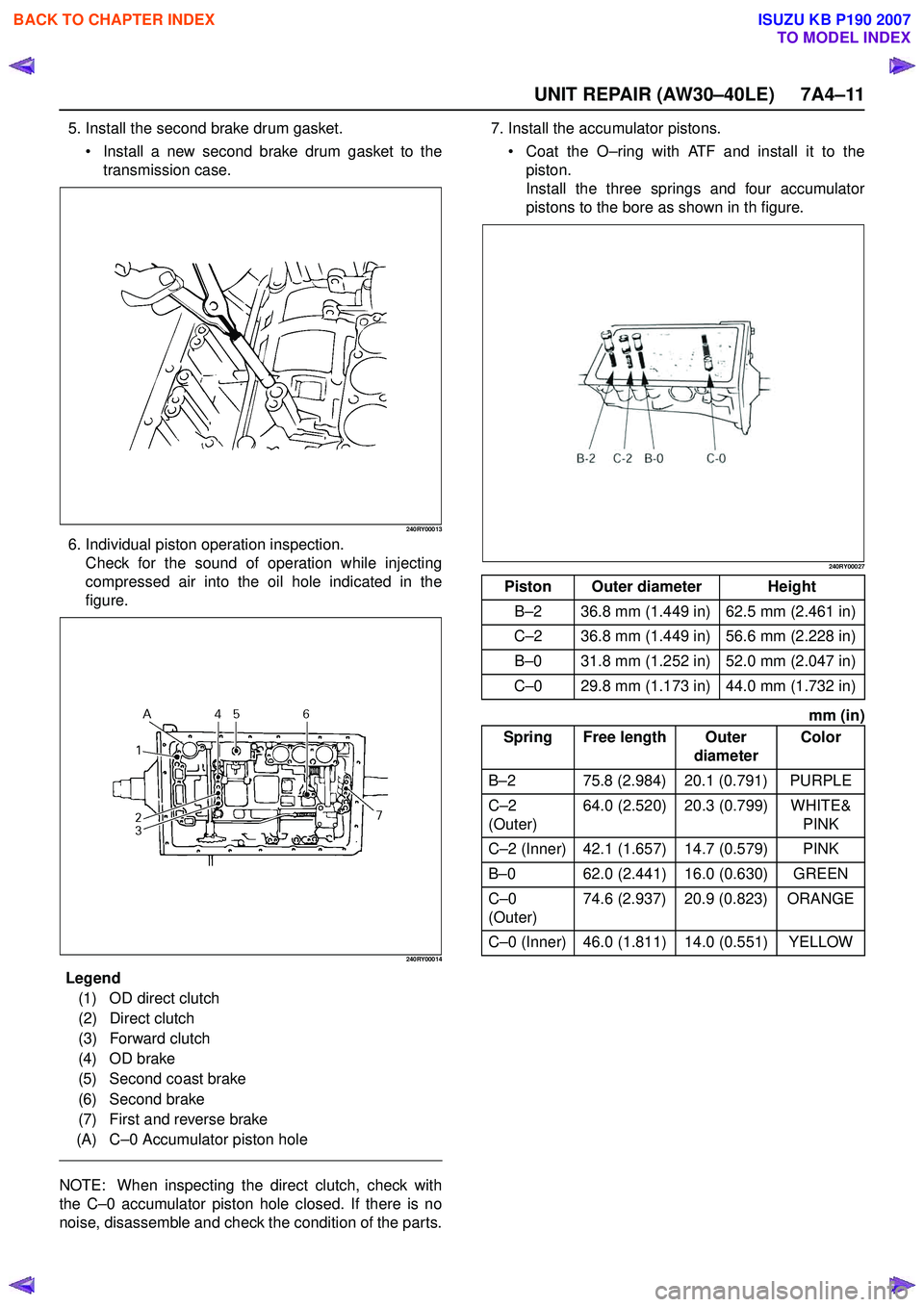
6. Individual piston operation inspection. Check for the sound of operation while injecting
compressed air into the oil hole indicated in the
figure.
240RY00014
E ndOFCallout
NOTE: When inspecting the direct clutch, check with
the C –0 accumulator piston hole closed. If there is no
noise, disassemble and check the condition of the parts. 7. Install the accumulator pistons.
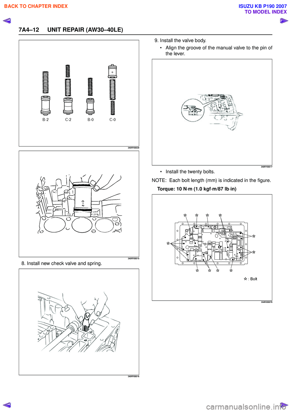
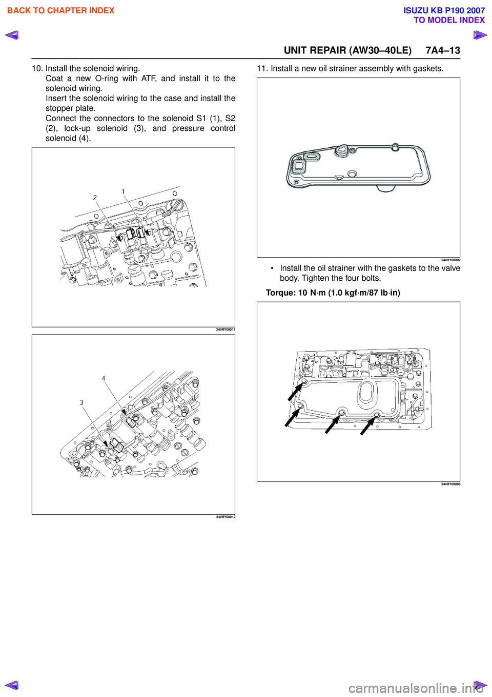
Coat the O –ring with ATF and install it to the
piston.
Install the three springs and four accumulator
pistons to the bore as shown in th figure.
240RY00027
mm (in)
Legend (1) OD direct clutch
(2) Direct clutch
(3) Forward clutch
(4) OD brake
(5) Second coast brake
(6) Second brake
(7) First and reverse brake
(A) C –0 Accumulator piston hole
Piston Outer diameter Height
B –2 36.8 mm (1.449 in) 62.5 mm (2.461 in)
C –2 36.8 mm (1.449 in) 56.6 mm (2.228 in)
B –0 31.8 mm (1.252 in) 52.0 mm (2.047 in)
C –0 29.8 mm (1.173 in) 44.0 mm (1.732 in)
Spring Free length Outer diameterColor
B –2 75.8 (2.984) 20.1 (0.791) PURPLE
C –2
(Outer) 64.0 (2.520) 20.3 (0.799) WHITE&
PINK
C –2 (Inner) 42.1 (1.657) 14.7 (0.579) PINK
B –0 62.0 (2.441) 16.0 (0.630) GREEN
C –0
(Outer) 74.6 (2.937) 20.9 (0.823) ORANGE
C –0 (Inner) 46.0 (1.811) 14.0 (0.551) YELLOW
BACK TO CHAPTER INDEX
TO MODEL INDEX
ISUZU KB P190 2007
Page 4147 of 6020
7A4–12 UNIT REPAIR (AW30–40LE)
240RY00029
240RY00010
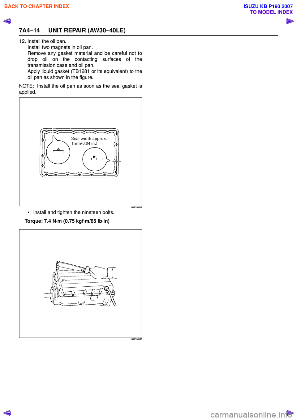
8. Install new check valve and spring.
240RY00016
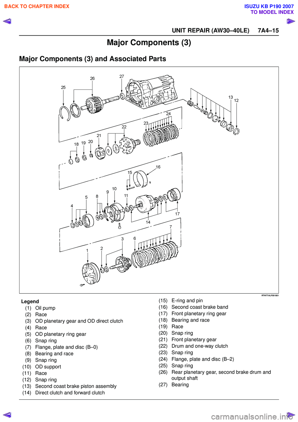
9. Install the valve body. Align the groove of the manual valve to the pin of
the lever.
240RY00017
Install the twenty bolts.
NOTE: Each bolt length (mm) is indicated in the figure. Torque: 10 N ·m (1.0 kgf ·m/87 lb ·in)
244R200078
BACK TO CHAPTER INDEX
TO MODEL INDEX
ISUZU KB P190 2007
Page 4148 of 6020
UNIT REPAIR (AW30–40LE) 7A4–13
10. Install the solenoid wiring.Coat a new O-ring with ATF, and install it to the
solenoid wiring.
Insert the solenoid wiring to the case and install the
stopper plate.
Connect the connectors to the solenoid S1 (1), S2
(2), lock-up solenoid (3), and pressure control
solenoid (4).
249RY00011
249RY00012
11. Install a new oil strainer assembly with gaskets.
244RY00002
Install the oil strainer with the gaskets to the valve
body. Tighten the four bolts.
Torque: 10 N ·m (1.0 kgf ·m/87 lb ·in)
244RY00003
BACK TO CHAPTER INDEX
TO MODEL INDEX
ISUZU KB P190 2007
Page 4149 of 6020
7A4–14 UNIT REPAIR (AW30–40LE)
12. Install the oil pan.Install two magnets in oil pan.
Remove any gasket material and be careful not to
drop oil on the contacting surfaces of the
transmission case and oil pan.
Apply liquid gasket (TB1281 or its equivalent) to the
oil pan as shown in the figure.
NOTE: Install the oil pan as soon as the seal gasket is
applied.
240RY00019
Install and tighten the nineteen bolts.
Torque: 7.4 N ·m (0.75 kgf ·m/65 lb ·in)
240RY00020
BACK TO CHAPTER INDEX
TO MODEL INDEX
ISUZU KB P190 2007
Page 4150 of 6020
UNIT REPAIR (AW30–40LE) 7A4–15
Major Components (3)
Major Components (3) and Associated Parts
RTW77ALF001801
EndOFCallout
Legend(1) Oil pump
(2) Race
(3) OD planetary gear and OD direct clutch
(4) Race
(5) OD planetary ring gear
(6) Snap ring
(7) Flange, plate and disc (B –0)
(8) Bearing and race
(9) Snap ring
(10) OD support
(11) Race
(12) Snap ring
(13) Second coast brake piston assembly
(14) Direct clutch and forward clutch (15) E-ring and pin
(16) Second coast brake band
(17) Front planetary ring gear
(18) Bearing and race
(19) Race
(20) Snap ring
(21) Front planetary gear
(22) Drum and one-way clutch
(23) Snap ring
(24) Flange, plate and disc (B –2)
(25) Snap ring
(26) Rear planetary gear, second brake drum and output shaft
(27) Bearing
BACK TO CHAPTER INDEX
TO MODEL INDEX
ISUZU KB P190 2007
Trending: gas tank size, 4wd switch, glove box, check engine light, coolant temperature, FLASH CODE, oil change
