ISUZU KB P190 2007 Workshop Repair Manual
KB P190 2007
ISUZU
ISUZU
https://www.carmanualsonline.info/img/61/57177/w960_57177-0.png
ISUZU KB P190 2007 Workshop Repair Manual
Trending: air condition, air suspension, checking oil, clock, spare tire, sport mode, remote control
Page 5111 of 6020
ELECTRICAL-BODY AND CHASSIS 8A-173
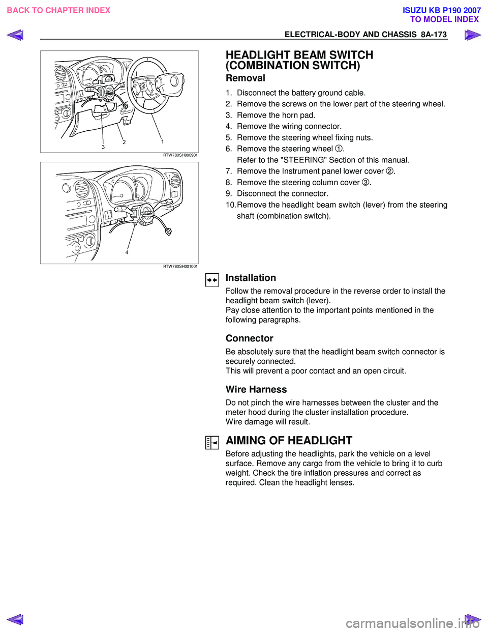
RTW 780SH000901
RTW 780SH001001
HEADLIGHT BEAM SWITCH
(COMBINATION SWITCH)
Removal
1. Disconnect the battery ground cable.
2. Remove the screws on the lower part of the steering wheel.
3. Remove the horn pad.
4. Remove the wiring connector.
5. Remove the steering wheel fixing nuts.
6. Remove the steering wheel
1.
Refer to the "STEERING" Section of this manual.
7. Remove the Instrument panel lower cover
2.
8. Remove the steering column cover
3.
9. Disconnect the connector.
10. Remove the headlight beam switch (lever) from the steering shaft (combination switch).
Installation
Follow the removal procedure in the reverse order to install the
headlight beam switch (lever).
Pay close attention to the important points mentioned in the
following paragraphs.
Connector
Be absolutely sure that the headlight beam switch connector is
securely connected.
This will prevent a poor contact and an open circuit.
Wire Harness
Do not pinch the wire harnesses between the cluster and the
meter hood during the cluster installation procedure.
W ire damage will result.
AIMING OF HEADLIGHT
Before adjusting the headlights, park the vehicle on a level
surface. Remove any cargo from the vehicle to bring it to curb
weight. Check the tire inflation pressures and correct as
required. Clean the headlight lenses.
BACK TO CHAPTER INDEX TO MODEL INDEXISUZU KB P190 2007
Page 5112 of 6020
8A-174 ELECTRICAL-BODY AND CHASSIS
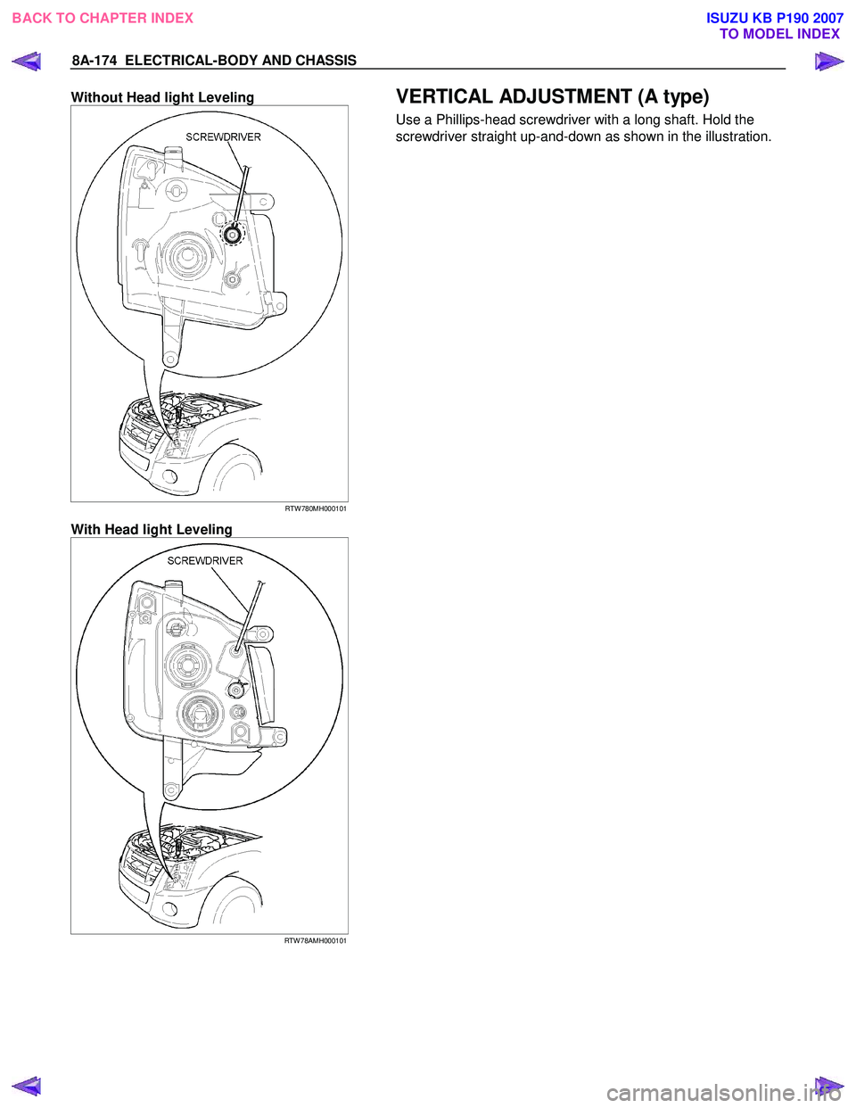
Without Head light Leveling
RTW 780MH000101
With Head light Leveling
RTW 78AMH000101
VERTICAL ADJUSTMENT (A type)
Use a Phillips-head screwdriver with a long shaft. Hold the
screwdriver straight up-and-down as shown in the illustration.
BACK TO CHAPTER INDEX TO MODEL INDEXISUZU KB P190 2007
Page 5113 of 6020
ELECTRICAL-BODY AND CHASSIS 8A-175
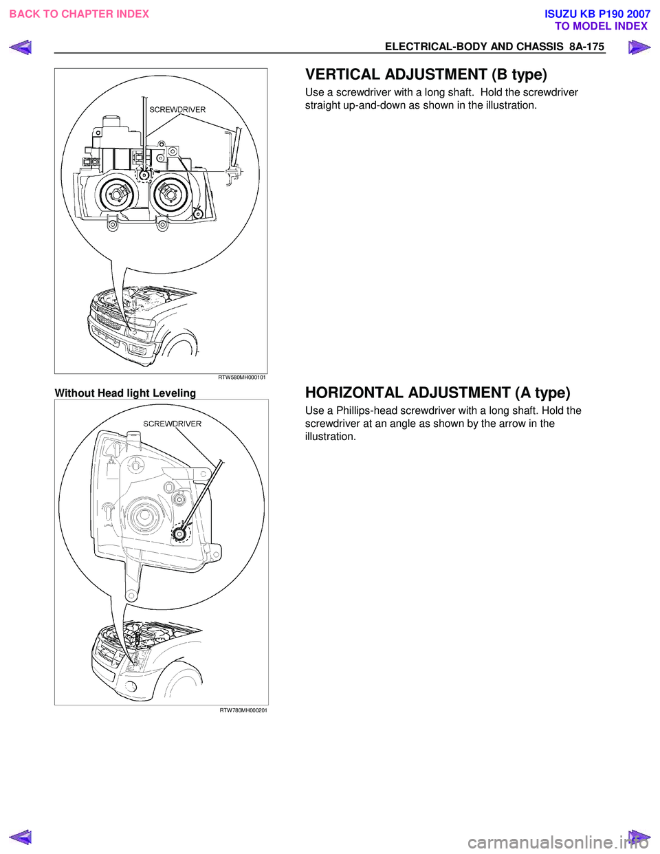
RTW 580MH000101
VERTICAL ADJUSTMENT (B type)
Use a screwdriver with a long shaft. Hold the screwdriver
straight up-and-down as shown in the illustration.
Without Head light Leveling
RTW 780MH000201
HORIZONTAL ADJUSTMENT (A type)
Use a Phillips-head screwdriver with a long shaft. Hold the
screwdriver at an angle as shown by the arrow in the
illustration.
BACK TO CHAPTER INDEX TO MODEL INDEXISUZU KB P190 2007
Page 5114 of 6020
8A-176 ELECTRICAL-BODY AND CHASSIS
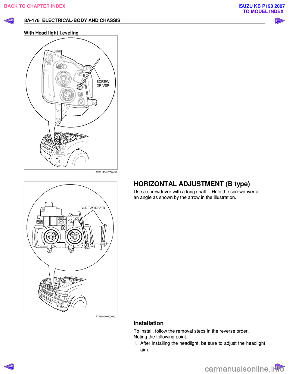
With Head light Leveling
RTW 78AMH000201
RTW 580MH000201
HORIZONTAL ADJUSTMENT (B type)
Use a screwdriver with a long shaft. Hold the screwdriver at
an angle as shown by the arrow in the illustration.
Installation
To install, follow the removal steps in the reverse order.
Noting the following point:
1.
After installing the headlight, be sure to adjust the headlight
aim.
BACK TO CHAPTER INDEX TO MODEL INDEXISUZU KB P190 2007
Page 5115 of 6020
ELECTRICAL-BODY AND CHASSIS 8A-177
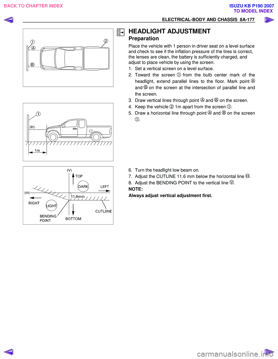
HEADLIGHT ADJUSTMENT
Preparation
Place the vehicle with 1 person in driver seat on a level surface
and check to see if the inflation pressure of the tires is correct,
the lenses are clean, the battery is sufficiently charged, and
adjust to place vehicle by using the screen.
1. Set a vertical screen on a level surface.
2. Toward the screen
1from the bulb center mark of the
headlight, extend parallel lines to the floor. Mark point
A
and B on the screen at the intersection of parallel line and
the screen.
3. Draw vertical lines through point
A and B on the screen.
4. Keep the vehicle 2 1m apart from the screen 1.
5. Draw a horizontal line through point
A and Bon the screen
1.
6. Turn the headlight low beam on.
7. Adjust the CUTLINE 11.6 mm below the horizontal line
H.
8. Adjust the BENDING POINT to the vertical line
V.
NOTE:
Always adjust vertical adjustment first.
BACK TO CHAPTER INDEX TO MODEL INDEXISUZU KB P190 2007
Page 5116 of 6020
8A-178 ELECTRICAL-BODY AND CHASSIS
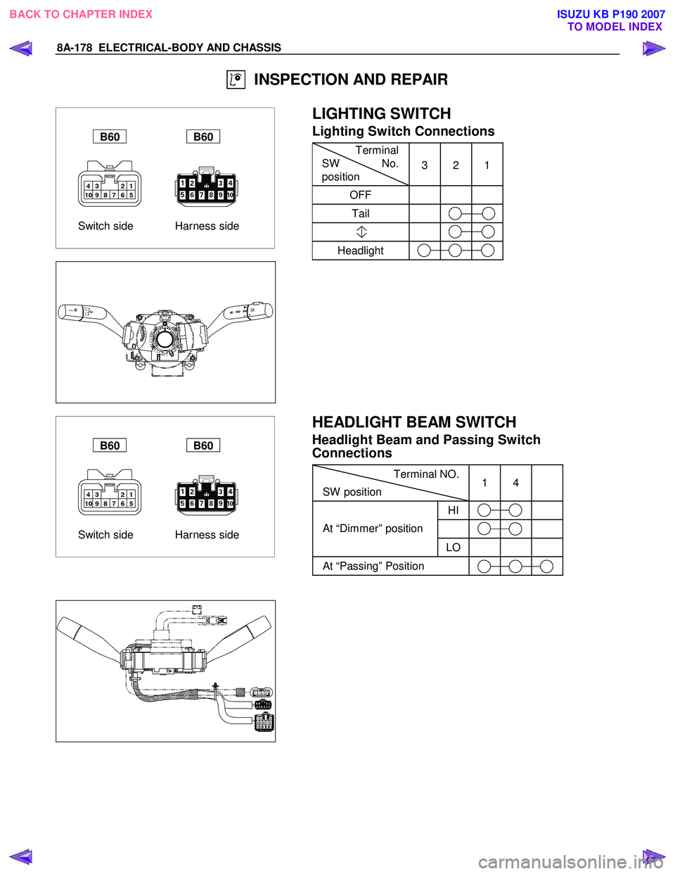
INSPECTION AND REPAIR
Switch side Harness side
B60 B60
LIGHTING SWITCH
Lighting Switch Connections
Terminal
SW No.
position 3 2 1
OFF
Tail
Headlight
Switch side Harness side
B60 B60
HEADLIGHT BEAM SWITCH
Headlight Beam and Passing Switch
Connections
Terminal NO.
SW position 1 4
HI
At “Dimmer” position
LO
At “Passing” Position
BACK TO CHAPTER INDEX
TO MODEL INDEXISUZU KB P190 2007
Page 5117 of 6020
ELECTRICAL-BODY AND CHASSIS 8A-179
RTW 78ASH002901
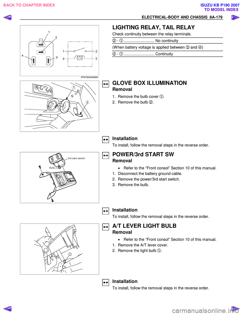
LIGHTING RELAY, TAIL RELAY
Check continuity between the relay terminals.
2 - 1............................ No continuity
(W hen battery voltage is applied between 3 and 4)
2 - 1............................ Continuity
GLOVE BOX ILLUMINATION
Removal
1. Remove the bulb cover 1.
2. Remove the bulb
2.
Installation
To install, follow the removal steps in the reverse order.
POWER/3rd START SW
Removal
• Refer to the “Front consol” Section 10 of this manual.
1. Disconnect the battery ground cable.
2. Remove the power/3rd start switch.
3. Remove the bulb.
Installation
To install, follow the removal steps in the reverse order.
A/T LEVER LIGHT BULB
Removal
• Refer to the “Front consol” Section 10 of this manual.
1. Remove the A/T lever cover.
2. Remove the light bulb
1.
Installation
To install, follow the removal steps in the reverse order.
BACK TO CHAPTER INDEX TO MODEL INDEXISUZU KB P190 2007
Page 5118 of 6020
8A-180 ELECTRICAL-BODY AND CHASSIS
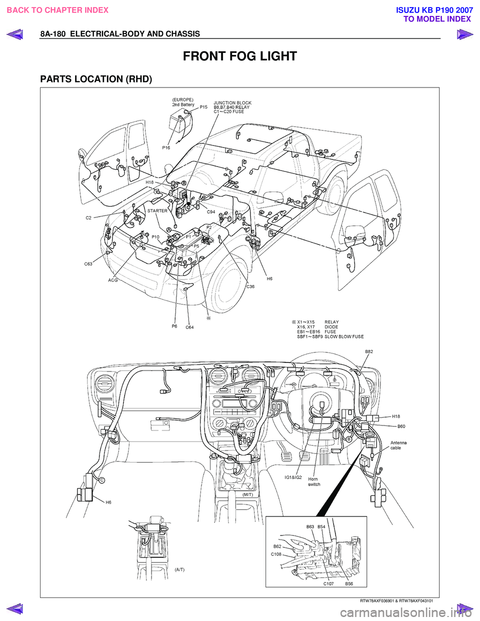
FRONT FOG LIGHT
PARTS LOCATION (RHD)
RTW 78AXF036901 & RTW 78AXF043101
BACK TO CHAPTER INDEX
TO MODEL INDEXISUZU KB P190 2007
Page 5119 of 6020
ELECTRICAL-BODY AND CHASSIS 8A-181
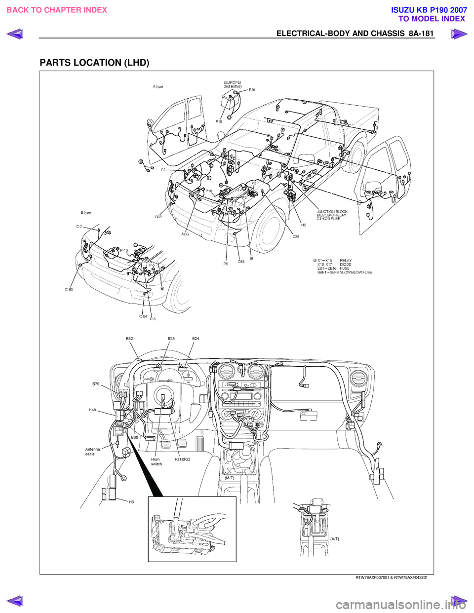
PARTS LOCATION (LHD)
RTW 78AXF037001 & RTW 78AXF043201
BACK TO CHAPTER INDEX
TO MODEL INDEXISUZU KB P190 2007
Page 5120 of 6020
8A-182 ELECTRICAL-BODY AND CHASSIS
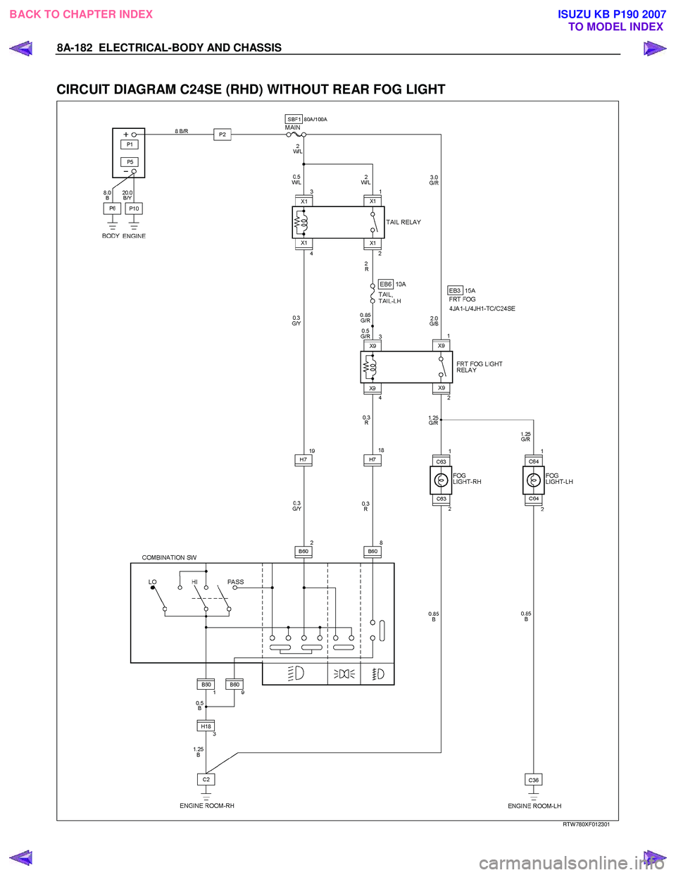
CIRCUIT DIAGRAM C24SE (RHD) WITHOUT REAR FOG LIGHT
RTW 780XF012301
BACK TO CHAPTER INDEX
TO MODEL INDEXISUZU KB P190 2007
Trending: steering rack, OBD port, turn signal bulb, navigation, change wheel, ad blue, wheel

