ISUZU KB P190 2007 Workshop Repair Manual
KB P190 2007
ISUZU
ISUZU
https://www.carmanualsonline.info/img/61/57177/w960_57177-0.png
ISUZU KB P190 2007 Workshop Repair Manual
Trending: cruise control, change language, jacking points, Alarm, radiator, keyless, 4JH1
Page 5131 of 6020
ELECTRICAL-BODY AND CHASSIS 8A-193
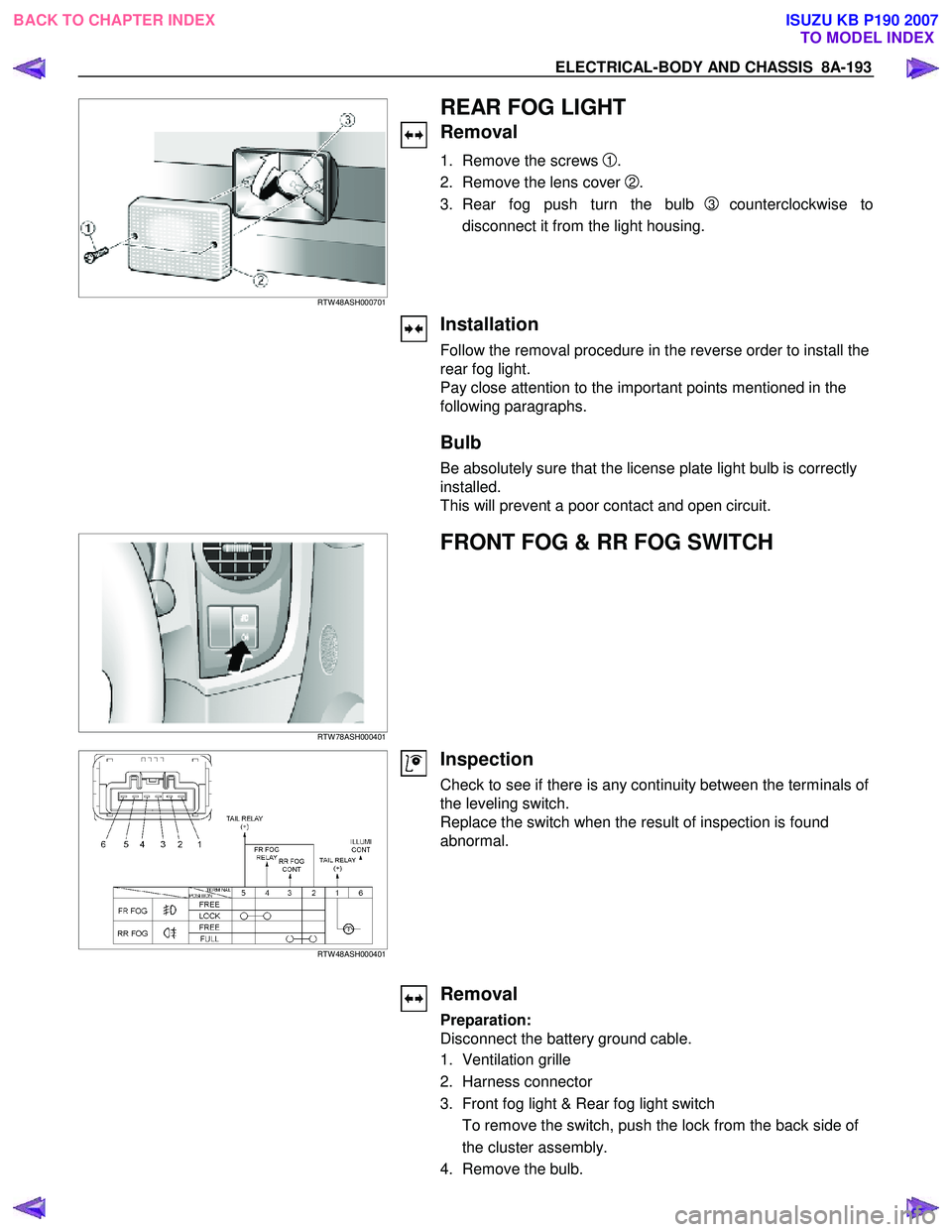
RTW 48ASH000701
REAR FOG LIGHT
Removal
1. Remove the screws 1.
2. Remove the lens cover
2.
3. Rear fog push turn the bulb
3 counterclockwise to
disconnect it from the light housing.
Installation
Follow the removal procedure in the reverse order to install the
rear fog light.
Pay close attention to the important points mentioned in the
following paragraphs.
Bulb
Be absolutely sure that the license plate light bulb is correctly
installed.
This will prevent a poor contact and open circuit.
RTW 78ASH000401
FRONT FOG & RR FOG SWITCH
RTW 48ASH000401
Inspection
Check to see if there is any continuity between the terminals of
the leveling switch.
Replace the switch when the result of inspection is found
abnormal.
Removal
Preparation:
Disconnect the battery ground cable.
1. Ventilation grille
2. Harness connector
3. Front fog light & Rear fog light switch To remove the switch, push the lock from the back side of
the cluster assembly.
4. Remove the bulb.
BACK TO CHAPTER INDEX TO MODEL INDEXISUZU KB P190 2007
Page 5132 of 6020
8A-194 ELECTRICAL-BODY AND CHASSIS
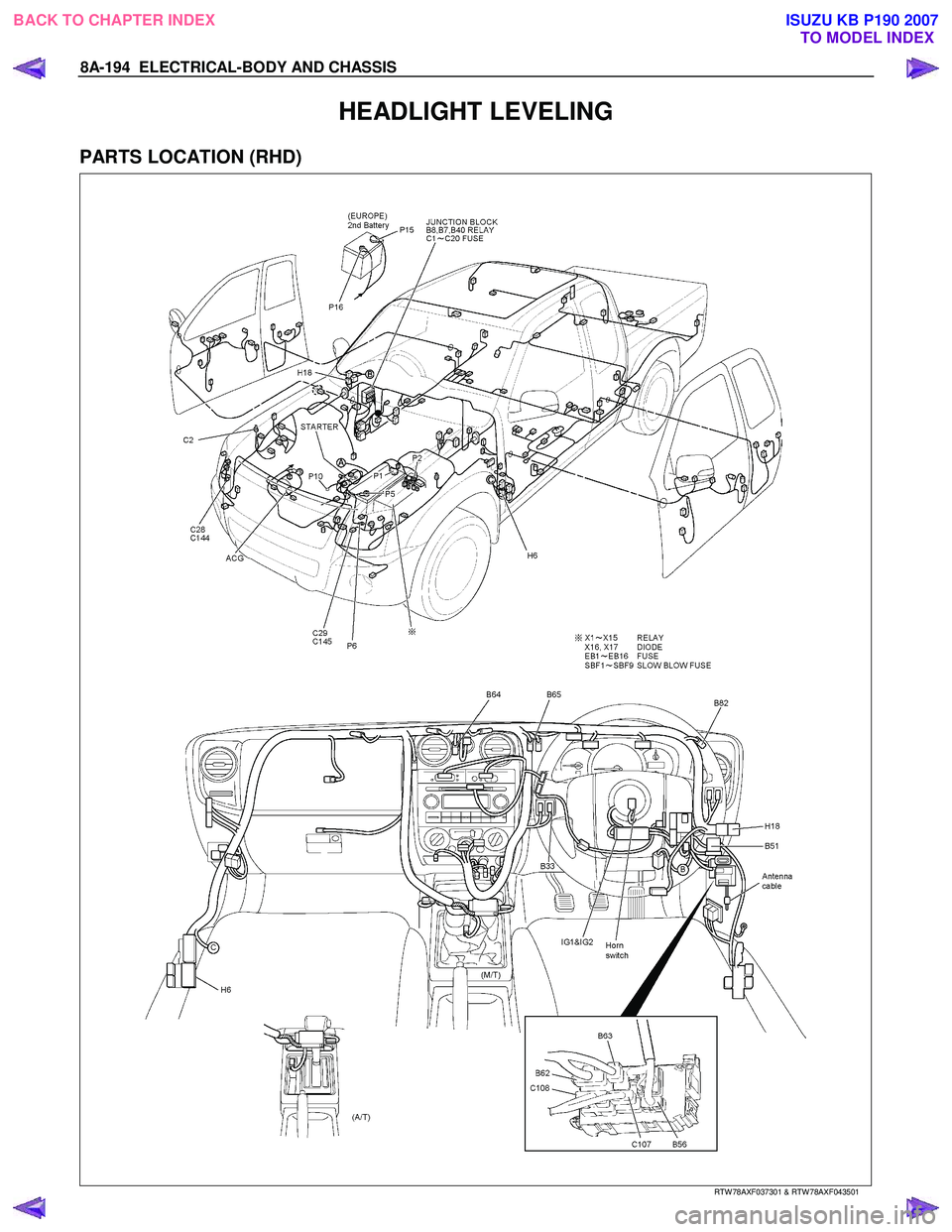
HEADLIGHT LEVELING
PARTS LOCATION (RHD)
RTW 78AXF037301 & RTW 78AXF043501
BACK TO CHAPTER INDEX TO MODEL INDEXISUZU KB P190 2007
Page 5133 of 6020
ELECTRICAL-BODY AND CHASSIS 8A-195
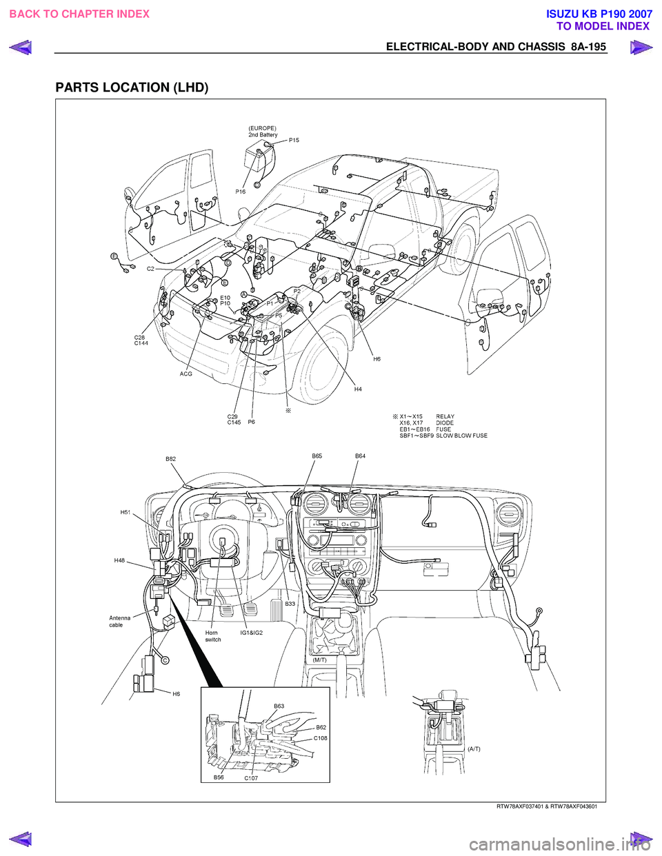
PARTS LOCATION (LHD)
RTW 78AXF037401 & RTW 78AXF043601
BACK TO CHAPTER INDEX
TO MODEL INDEXISUZU KB P190 2007
Page 5134 of 6020
8A-196 ELECTRICAL-BODY AND CHASSIS
CIRCUIT DIAGRAM C24SE (RHD)
RTW 680XF007601
BACK TO CHAPTER INDEX
TO MODEL INDEXISUZU KB P190 2007
Page 5135 of 6020
ELECTRICAL-BODY AND CHASSIS 8A-197
CIRCUIT DIAGRAM C24SE (LHD)
RTW 680XF007501
BACK TO CHAPTER INDEX
TO MODEL INDEXISUZU KB P190 2007
Page 5136 of 6020
8A-198 ELECTRICAL-BODY AND CHASSIS
CIRCUIT DIAGRAM 4JJ1-TC / 4JK1-TC EXCEPT SOUTH AFRICA, 4JA1T (L) (LHD)
RTW 78AXF023001
BACK TO CHAPTER INDEX TO MODEL INDEXISUZU KB P190 2007
Page 5137 of 6020
ELECTRICAL-BODY AND CHASSIS 8A-199
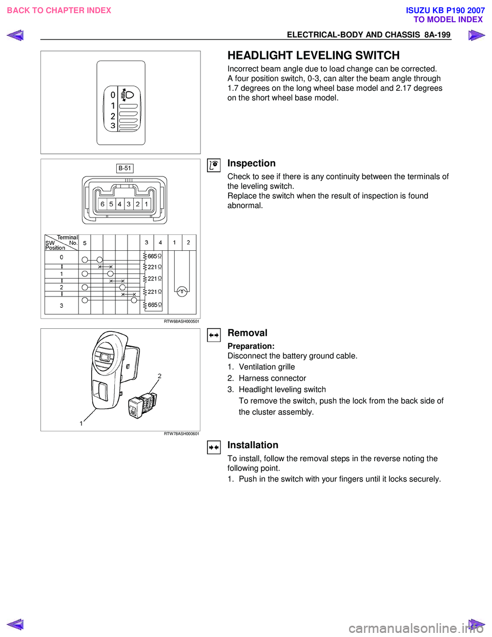
HEADLIGHT LEVELING SWITCH
Incorrect beam angle due to load change can be corrected.
A four position switch, 0-3, can alter the beam angle through
1.7 degrees on the long wheel base model and 2.17 degrees
on the short wheel base model.
RTW 68ASH000501
Inspection
Check to see if there is any continuity between the terminals of
the leveling switch.
Replace the switch when the result of inspection is found
abnormal.
RTW 78ASH000601
Removal
Preparation:
Disconnect the battery ground cable.
1. Ventilation grille
2. Harness connector
3. Headlight leveling switch To remove the switch, push the lock from the back side of
the cluster assembly.
Installation
To install, follow the removal steps in the reverse noting the
following point.
1. Push in the switch with your fingers until it locks securely.
BACK TO CHAPTER INDEX TO MODEL INDEXISUZU KB P190 2007
Page 5138 of 6020
8A-200 ELECTRICAL-BODY AND CHASSIS
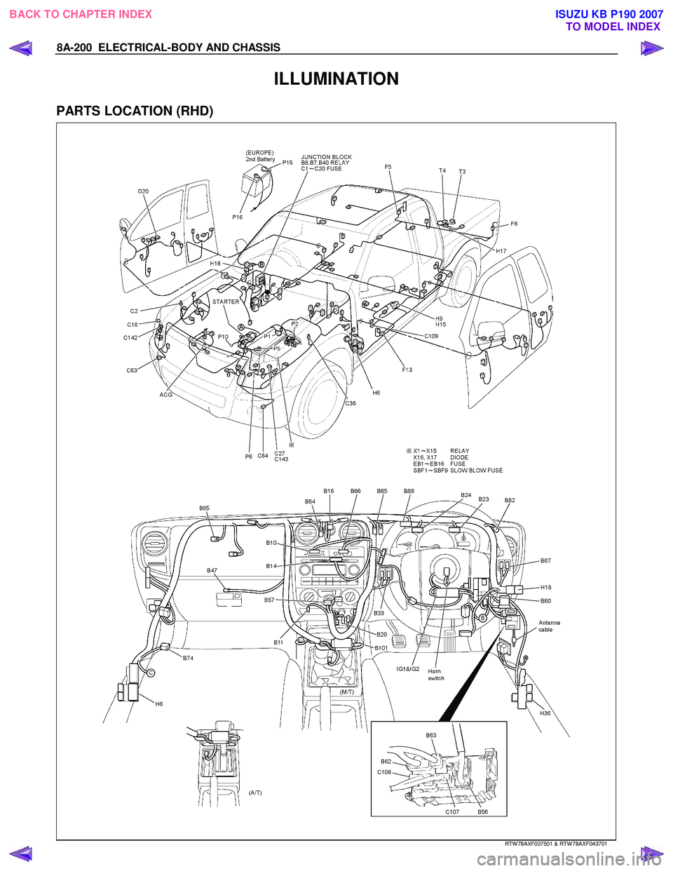
ILLUMINATION
PARTS LOCATION (RHD)
RTW 78AXF037501 & RTW 78AXF043701
BACK TO CHAPTER INDEX
TO MODEL INDEXISUZU KB P190 2007
Page 5139 of 6020
ELECTRICAL-BODY AND CHASSIS 8A-201
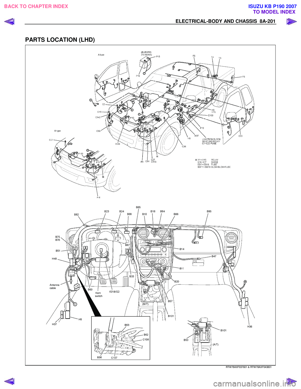
PARTS LOCATION (LHD)
RTW 78AXF037601 & RTW 78AXF043801
BACK TO CHAPTER INDEX
TO MODEL INDEXISUZU KB P190 2007
Page 5140 of 6020
8A-202 ELECTRICAL-BODY AND CHASSIS
CIRCUIT DIAGRAM C24SE (RHD) WITHOUT ILLUMINATION CONTROL
RTW 680XF007701
BACK TO CHAPTER INDEX TO MODEL INDEXISUZU KB P190 2007
Trending: engine mount, refrigerant type, clock reset, lock, check oil, navigation, oil reset

