ISUZU KB P190 2007 Workshop Repair Manual
KB P190 2007
ISUZU
ISUZU
https://www.carmanualsonline.info/img/61/57177/w960_57177-0.png
ISUZU KB P190 2007 Workshop Repair Manual
Trending: oil capacity, lock, key, keyless, oil type, tyre pressure, jump cable
Page 5371 of 6020
ELECTRICAL-BODY AND CHASSIS 8A-433
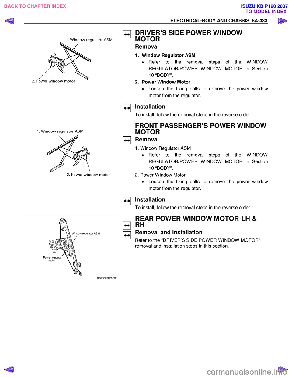
DRIVER’S SIDE POWER WINDOW
MOTOR
Removal
1. Window Regulator ASM
• Refer to the removal steps of the W INDOW
REGULATOR/POW ER W INDOW MOTOR in Section
10 “BODY”.
2. Power Window Motor • Loosen the fixing bolts to remove the power windo
w
motor from the regulator.
Installation
To install, follow the removal steps in the reverse order.
FRONT PASSENGER’S POWER WINDOW
MOTOR
Removal
1. W indow Regulator ASM
• Refer to the removal steps of the W INDOW
REGULATOR/POW ER W INDOW MOTOR in Section
10 “BODY”.
2. Power W indow Motor • Loosen the fixing bolts to remove the power windo
w
motor from the regulator.
Installation
To install, follow the removal steps in the reverse order.
RTW 580SH002901
REAR POWER WINDOW MOTOR-LH &
RH
Removal and Installation
Refer to the “DRIVER’S SIDE POW ER W INDOW MOTOR”
removal and installation steps in this section.
BACK TO CHAPTER INDEX TO MODEL INDEXISUZU KB P190 2007
Page 5372 of 6020
8A-434 ELECTRICAL-BODY AND CHASSIS
INSPECTION AND REPAIR
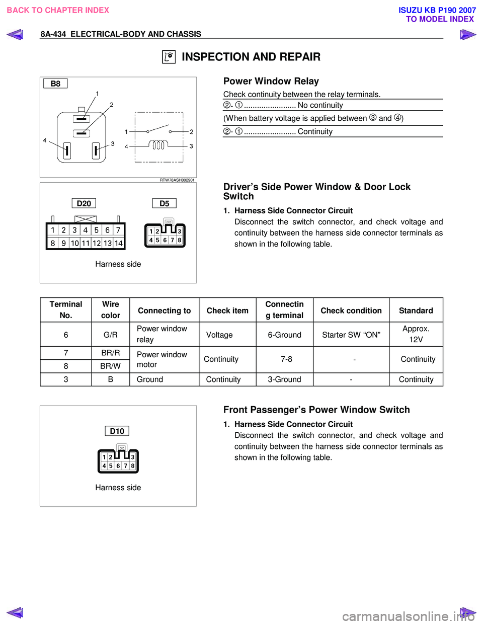
B8
RTW 78ASH002901
Power Window Relay
Check continuity between the relay terminals.
2- 1........................ No continuity
(W hen battery voltage is applied between
3 and 4)
2- 1........................ Continuity
Harness side
D20 D5
Driver’s Side Power Window & Door Lock
Switch
1. Harness Side Connector Circuit
Disconnect the switch connector, and check voltage and continuity between the harness side connector terminals as
shown in the following table.
Terminal No. Wire
color Connecting to Check item Connectin
g terminal Check condition Standard
6 G/R Power window
relay Voltage 6-Ground Starter SW “ON” Approx.
12V
7 BR/R Power window
8 BR/W motor
3 B Ground Continuity 3-Ground - Continuity
Harness side
D10
Front Passenger’s Power Window Switch
1. Harness Side Connector Circuit
Disconnect the switch connector, and check voltage and continuity between the harness side connector terminals as
shown in the following table.
Continuity
-
7-8
Continuity
BACK TO CHAPTER INDEX
TO MODEL INDEXISUZU KB P190 2007
Page 5373 of 6020

ELECTRICAL-BODY AND CHASSIS 8A-435
Terminal No. Wire
color Connecting to Check item Connectin
g terminal Check condition Standard
6 G/R Power window
relay Voltage 6-Ground Starter SW “ON” Approx.
12V
8 BR/R
7 BR/W Power window
motor Continuity 8-7
- Continuity
1,3 B Ground Continuity 1,3-Ground - Continuity
Harness side
D12 D16
Rear Power Window Switch-LH & RH
1. Harness Side Connector Circuit
Disconnect the switch connector, and check voltage and continuity between the harness side connector terminals as
shown in the following tables.
D12 (RR-LH)
Terminal No. Wire
color Connecting to Check item Connectin
g terminal Check condition Standard
6 G/R Power window
relay Voltage 6-Ground Starter SW “ON” Approx.
12V
8 BR/R
7 BR/W Power window
motor Continuity 8-7
- Continuity
3 B
4 B Ground Continuity 3,4-Ground - Continuity
D16 (RR-RH)
Terminal
No. Wire
color Connecting to Check item Connectin
g terminal Check condition Standard
6 G/R Power window
relay Voltage 6-Ground Starter SW “ON” Approx.
12V
8 BR/R
7 BR/W Power window
motor Continuity 8-7
- Continuity
3 B Ground Continuity 3-Ground - Continuity
BACK TO CHAPTER INDEX
TO MODEL INDEXISUZU KB P190 2007
Page 5374 of 6020
8A-436 ELECTRICAL-BODY AND CHASSIS
Harness side
D5
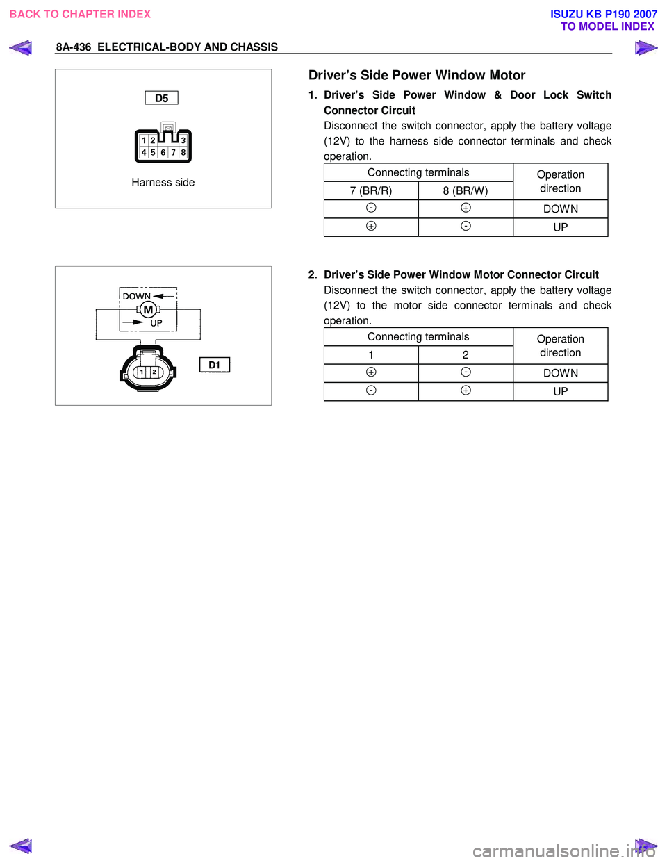
Driver’s Side Power Window Motor
1. Driver’s Side Power Window & Door Lock Switch
Connector Circuit
Disconnect the switch connector, apply the battery voltage (12V) to the harness side connector terminals and check
operation.
Connecting terminals Operation
7 (BR/R) 8 (BR/W ) direction
- + DOW N
+ - UP
D1
2. Driver’s Side Power Window Motor Connector Circuit
Disconnect the switch connector, apply the battery voltage (12V) to the motor side connector terminals and check
operation.
Connecting terminals Operation
1 2 direction
+ - DOW N
- + UP
BACK TO CHAPTER INDEX
TO MODEL INDEXISUZU KB P190 2007
Page 5375 of 6020
ELECTRICAL-BODY AND CHASSIS 8A-437
Harness side
D10
Front Passenger’s Power Window Motor
1. Front Passenger’s Power Window Switch Connector
Circuit
Disconnect the motor connector, apply the battery voltage (12V) to the harness side connector terminals and check
operation.
Connecting terminals Operation
8 (BR/R) 7 (BR/W ) direction
- + DOW N
+ - UP
D6
2. Front Passenger’s Power Window Motor Connector
Circuit
Disconnect the switch connector, apply the battery voltage (12V) to the motor side connector terminals and check
operation.
Connecting terminals Operation
1 2 direction
+ - DOW N
- + UP
BACK TO CHAPTER INDEX
TO MODEL INDEXISUZU KB P190 2007
Page 5376 of 6020
8A-438 ELECTRICAL-BODY AND CHASSIS
Harness side
D12
Rear Passenger’s Power Window Motor-LH
1. Rear Power Window Switch-LH Connector Circuit
Disconnect the motor connector, apply the battery voltage (12V) to the harness side connector terminals and check
operation.
Connecting terminals Operation
8 (BR/R) 7 (BR/W ) direction
- + DOW N
+ - UP
D11
2. Rear Power Window Motor-LH Connector Circuit
Disconnect the switch connector, apply the battery voltage (12V) to the motor side connector terminals and check
operation.
Connecting terminals Operation
1 2 direction
+ - DOW N
- + UP
BACK TO CHAPTER INDEX
TO MODEL INDEXISUZU KB P190 2007
Page 5377 of 6020
ELECTRICAL-BODY AND CHASSIS 8A-439
Harness side
D16
Rear Power Window Motor-RH
1. Rear Power Window Switch-RH Connector Circuit
Disconnect the motor connector, apply the battery voltage (12V) to the harness side connector terminals and check
operation.
Connecting terminals Operation
8 (BR/R) 7 (BR/W ) direction
- + DOW N
+ - UP
D15
2. Rear Power Window Motor-RH Connector Circuit
Disconnect the switch connector, apply the battery voltage (12V) to the motor side connector terminals and check
operation.
Connecting terminals Operation
1 2 direction
+ - DOW N
- + UP
BACK TO CHAPTER INDEX TO MODEL INDEXISUZU KB P190 2007
Page 5378 of 6020
8A-440 ELECTRICAL-BODY AND CHASSIS
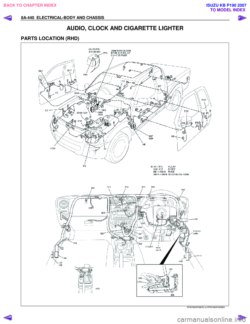
AUDIO, CLOCK AND CIGARETTE LIGHTER
PARTS LOCATION (RHD)
RTW 78AXF039701 & RTW 78AXF045901
BACK TO CHAPTER INDEX
TO MODEL INDEXISUZU KB P190 2007
Page 5379 of 6020
ELECTRICAL-BODY AND CHASSIS 8A-441
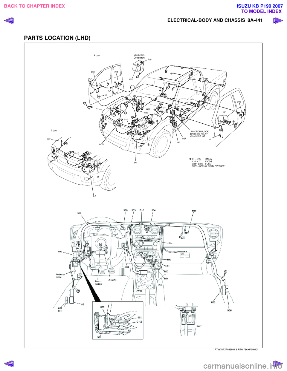
PARTS LOCATION (LHD)
RTW 78AXF039801 & RTW 78AXF046001
BACK TO CHAPTER INDEX TO MODEL INDEXISUZU KB P190 2007
Page 5380 of 6020
8A-442 ELECTRICAL-BODY AND CHASSIS
CIRCUIT DIAGRAM C24SE (RHD) Sheet 1/2
RTW 780XF014101
BACK TO CHAPTER INDEX TO MODEL INDEXISUZU KB P190 2007
Trending: cruise control, warning, maintenance schedule, service schedule, USB, wheel torque, catalytic converter
