sensor ISUZU KB P190 2007 Workshop Repair Manual
[x] Cancel search | Manufacturer: ISUZU, Model Year: 2007, Model line: KB P190, Model: ISUZU KB P190 2007Pages: 6020, PDF Size: 70.23 MB
Page 2421 of 6020
ENGINE DRIVEABILITY AND EMISSIONS 6E–251
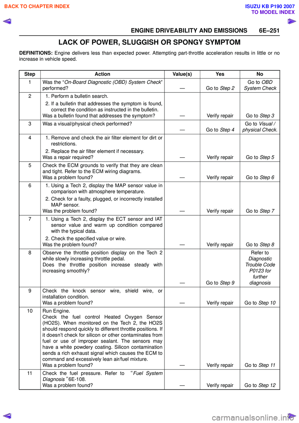
LACK OF POWER, SLUGGISH OR SPONGY SYMPTOM
DEFINITIONS: Engine delivers less than expected power. Attempting part-throttle acceleration results in little or no
increase in vehicle speed.
Step Action Value(s) Yes No
1 Was the “ On-Board Diagnostic (OBD) System Check ”
performed? — Go to Step 2Go to
OBD
System Check
2 1. Perform a bulletin search. 2. If a bulletin that addresses the symptom is found,correct the condition as instructed in the bulletin.
Was a bulletin found that addresses the symptom? — Verify repair Go to Step 3
3 Was a visual/physical check performed? —Go to Step 4Go to
Visual /
physical Check .
4 1. Remove and check the air filter element for dirt or restrictions.
2. Replace the air filter element if necessary.
Was a repair required? — Verify repair Go to Step 5
5 Check the ECM grounds to verify that they are clean and tight. Refer to the ECM wiring diagrams.
Was a problem found? — Verify repair Go to Step 6
6 1. Using a Tech 2, display the MAP sensor value in comparison with atmosphere temperature.
2. Check for a faulty, plugged, or incorrectly installed MAP sensor.
Was the problem found? — Verify repair Go to Step 7
7 1. Using a Tech 2, display the ECT sensor and IAT sensor value and warm up condition compared
with the typical data.
2. Check the specified value or wire.
Was the problem found? — Verify repair Go to Step 8
8 Observe the throttle position display on the Tech 2 while slowly increasing throttle pedal.
Does the throttle position increase steady with
increasing smoothly?
—Go to Step 9Refer to
Diagnostic
Trouble Code P0123 for further
diagnosis
9 Check the knock sensor wire, shield wire, or installation condition.
Was a problem found? — Verify repair Go to Step 10
10 Run Engine. Check the fuel control Heated Oxygen Sensor
(HO2S). When monitored on the Tech 2, the HO2S
should respond quickly to different throttle positions. If
it doesn’t check for silicon or other contaminates from
fuel or use of improper sealant. The sensors may
have a white powdery coating. Silicon contamination
sends a rich exhaust signal which causes the ECM to
command and excessively lean air/fuel mixture.
Was a problem found? — Verify repair Go to Step 11
11 Check the fuel pressure. Refer to “Fuel System
Diagnosis
” 6E-108.
Was a problem found? — Verify repair Go to Step 12
BACK TO CHAPTER INDEX
TO MODEL INDEX
ISUZU KB P190 2007
Page 2422 of 6020

6E–252 ENGINE DRIVEABILITY AND EMISSIONS
12 Monitor “B1S1 (Bank 1 Sensor 1) Status ” on the Tech
2.
Is the “ B1S1 (Bank 1 Sensor 1) Status ” in the rich
condition? — Verify repair Go to Step 13
13 Check items that can cause the engine to run rich. Refer to DTC P1167 “Fuel Supply System Rich During
Deceleration Fuel Cut Off”.
Was a problem found? — Verify repair Go to Step 14
14 Check items that can cause the engine to run lean. Refer to DTC P1171 “Fuel Supply System Lean
During Power Enrichment”.
Was a problem found? — Verify repair Go to Step 15
15 Check for proper ignition voltage output with a spark tester.
Was the problem found? — Verify repair Go to Step 16
16 1. Remove the spark plugs and check for gas or oil fouling cracks, wear, improper gap, burned
electrodes, heavy deposits, or improper heat
range.
2. If spark plugs are fouled, the cause of fouling must be determined before replacing the spark plugs.
Was a problem found? — Verify repair Go to Step 17
17 Drain sample fuel, visual inspection. Any suspecion about the fuel, such as discoloration,
particle, contamination, water, unusual smell, then
drain the fuel from fuel tank.
Replace the fuel from know vehicle source.
If any suspencion of alcohol contamination,
completely drain the fuel, replace by fuel from known
vehicle source. — Verify repair Go to Step 18
18 Check the exhaust system for a possible restriction: • Damaged or collapsed pipes
• Internal muffler failure
Was a problem found? — Verify repair Go to Step 19
19 Check for the following engine mechanical problems (refer to Engine Mechanical ):
• Low compression
• Leaking cylinder head gaskets
• Worn camshaft
• Loose timing belt
Was a problem found? — Verify repair Go to Step 20
20 1. Review all diagnostic procedures within this table. 2. If all procedures have been completed and nomalfunctions have been found, review/inspect the
following:
• Visual/physical inspection
• Tech 2 data
• All electrical connections within a suspected circuit and/or system
Was a problem found? — Verify repair Go to Step 21
Step
Action Value(s) Yes No
BACK TO CHAPTER INDEX
TO MODEL INDEX
ISUZU KB P190 2007
Page 2424 of 6020
6E–254 ENGINE DRIVEABILITY AND EMISSIONS
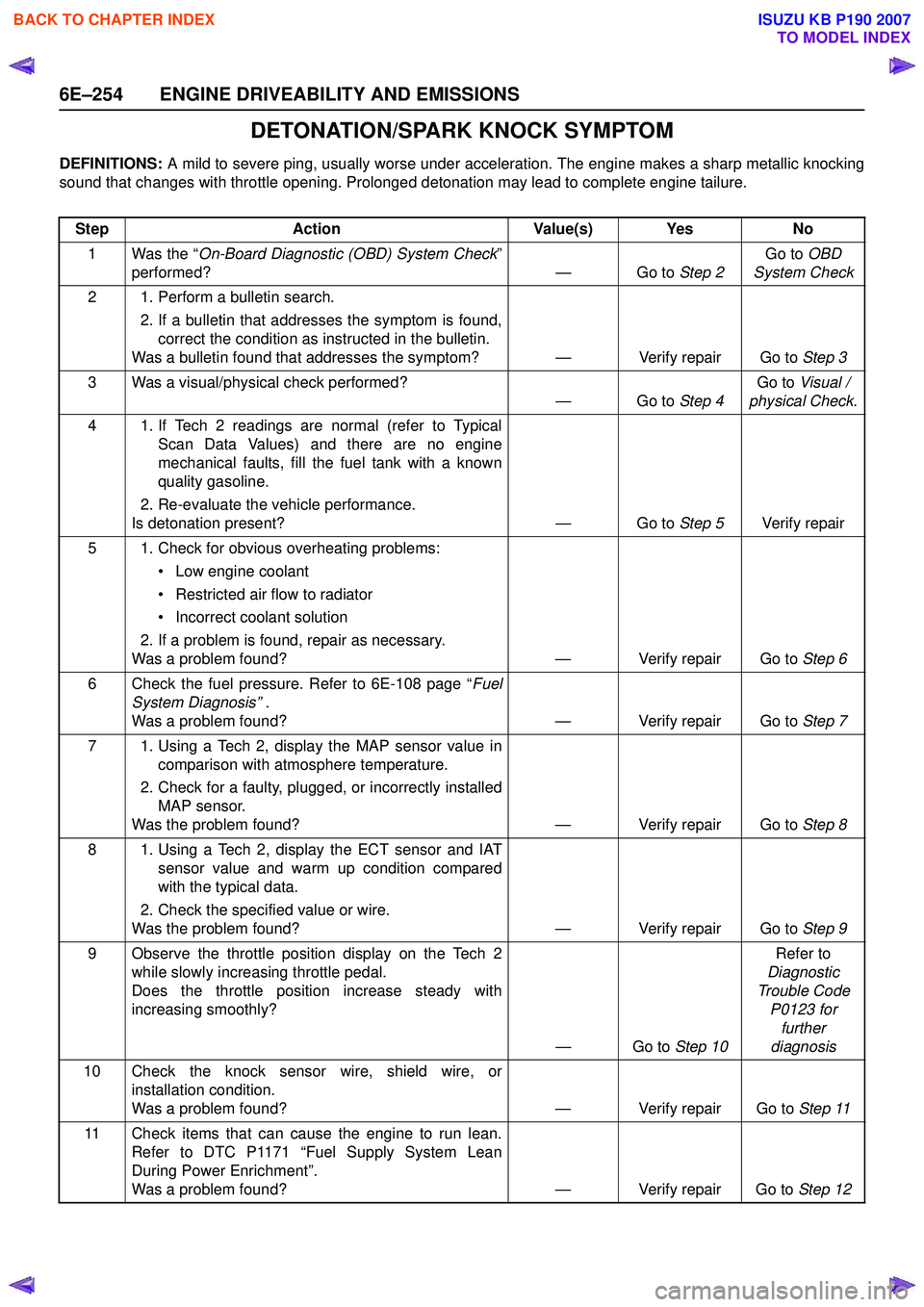
DETONATION/SPARK KNOCK SYMPTOM
DEFINITIONS: A mild to severe ping, usually worse under acceleration. The engine makes a sharp metallic knocking
sound that changes with throttle opening. Prolonged detonation may lead to complete engine tailure.
Step Action Value(s) Yes No
1 Was the “ On-Board Diagnostic (OBD) System Check ”
performed? — Go to Step 2Go to
OBD
System Check
2 1. Perform a bulletin search. 2. If a bulletin that addresses the symptom is found,correct the condition as instructed in the bulletin.
Was a bulletin found that addresses the symptom? — Verify repair Go to Step 3
3 Was a visual/physical check performed? —Go to Step 4Go to
Visual /
physical Check .
4 1. If Tech 2 readings are normal (refer to Typical Scan Data Values) and there are no engine
mechanical faults, fill the fuel tank with a known
quality gasoline.
2. Re-evaluate the vehicle performance.
Is detonation present? — Go to Step 5Verify repair
5 1. Check for obvious overheating problems: • Low engine coolant
• Restricted air flow to radiator
• Incorrect coolant solution
2. If a problem is found, repair as necessary.
Was a problem found? — Verify repair Go to Step 6
6 Check the fuel pressure. Refer to 6E-108 page “ Fuel
System Diagnosis” .
Was a problem found? — Verify repair Go to Step 7
7 1. Using a Tech 2, display the MAP sensor value in comparison with atmosphere temperature.
2. Check for a faulty, plugged, or incorrectly installed MAP sensor.
Was the problem found? — Verify repair Go to Step 8
8 1. Using a Tech 2, display the ECT sensor and IAT sensor value and warm up condition compared
with the typical data.
2. Check the specified value or wire.
Was the problem found? — Verify repair Go to Step 9
9 Observe the throttle position display on the Tech 2 while slowly increasing throttle pedal.
Does the throttle position increase steady with
increasing smoothly?
—Go to Step 10Refer to
Diagnostic
Trouble Code P0123 for further
diagnosis
10 Check the knock sensor wire, shield wire, or installation condition.
Was a problem found? — Verify repair Go to Step 11
11 Check items that can cause the engine to run lean. Refer to DTC P1171 “Fuel Supply System Lean
During Power Enrichment”.
Was a problem found? — Verify repair Go to Step 12
BACK TO CHAPTER INDEX
TO MODEL INDEX
ISUZU KB P190 2007
Page 2426 of 6020
6E–256 ENGINE DRIVEABILITY AND EMISSIONS
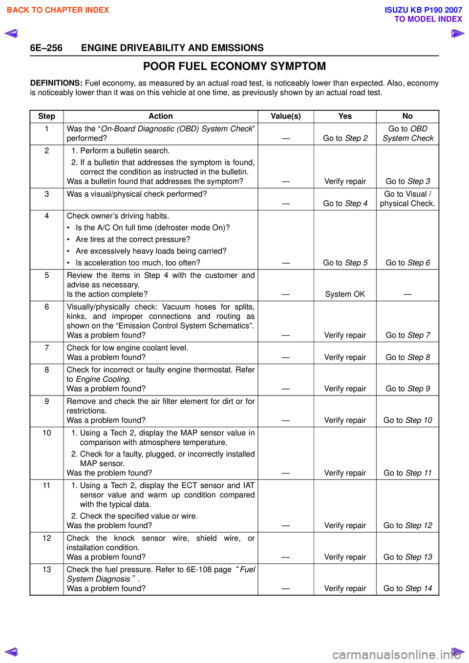
POOR FUEL ECONOMY SYMPTOM
DEFINITIONS: Fuel economy, as measured by an actual road test, is noticeably lower than expected. Also, economy
is noticeably lower than it was on this vehicle at one time, as previously shown by an actual road test.
Step Action Value(s) Yes No
1 Was the “ On-Board Diagnostic (OBD) System Check ”
performed? — Go to Step 2Go to
OBD
System Check
2 1. Perform a bulletin search. 2. If a bulletin that addresses the symptom is found,correct the condition as instructed in the bulletin.
Was a bulletin found that addresses the symptom? — Verify repair Go to Step 3
3 Was a visual/physical check performed? —Go to Step 4Go to Visual /
physical Check.
4 Check owner’s driving habits. • Is the A/C On full time (defroster mode On)?
• Are tires at the correct pressure?
• Are excessively heavy loads being carried?
• Is acceleration too much, too often? — Go to Step 5Go to Step 6
5 Review the items in Step 4 with the customer and advise as necessary.
Is the action complete? — System OK —
6 Visually/physically check: Vacuum hoses for splits, kinks, and improper connections and routing as
shown on the “Emission Control System Schematics”.
Was a problem found? — Verify repair Go to Step 7
7 Check for low engine coolant level. Was a problem found? — Verify repair Go to Step 8
8 Check for incorrect or faulty engine thermostat. Refer to Engine Cooling .
Was a problem found? — Verify repair Go to Step 9
9 Remove and check the air filter element for dirt or for restrictions.
Was a problem found? — Verify repair Go to Step 10
10 1. Using a Tech 2, display the MAP sensor value in comparison with atmosphere temperature.
2. Check for a faulty, plugged, or incorrectly installed MAP sensor.
Was the problem found? — Verify repair Go to Step 11
11 1. Using a Tech 2, display the ECT sensor and IAT sensor value and warm up condition compared
with the typical data.
2. Check the specified value or wire.
Was the problem found? — Verify repair Go to Step 12
12 Check the knock sensor wire, shield wire, or installation condition.
Was a problem found? — Verify repair Go to Step 13
13 Check the fuel pressure. Refer to 6E-108 page “Fuel
System Diagnosis
” .
Was a problem found? — Verify repair Go to Step 14
BACK TO CHAPTER INDEX
TO MODEL INDEX
ISUZU KB P190 2007
Page 2427 of 6020
ENGINE DRIVEABILITY AND EMISSIONS 6E–257
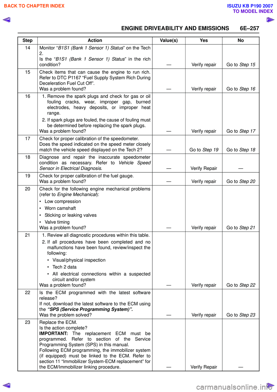
14 Monitor “B1S1 (Bank 1 Sensor 1) Status ” on the Tech
2.
Is the “ B1S1 (Bank 1 Sensor 1) Status ” in the rich
condition? — Verify repair Go to Step 15
15 Check items that can cause the engine to run rich. Refer to DTC P1167 “Fuel Supply System Rich During
Deceleration Fuel Cut Off”.
Was a problem found? — Verify repair Go to Step 16
16 1. Remove the spark plugs and check for gas or oil fouling cracks, wear, improper gap, burned
electrodes, heavy deposits, or improper heat
range.
2. If spark plugs are fouled, the cause of fouling must be determined before replacing the spark plugs.
Was a problem found? — Verify repair Go to Step 17
17 Check for proper calibration of the speedometer. Does the speed indicated on the speed meter closely
match the vehicle speed displayed on the Tech 2? — Go to Step 19Go to Step 18
18 Diagnose and repair the inaccurate speedometer condition as necessary. Refer to Vehicle Speed
Sensor in Electrical Diagnosis . — Verify Repair —
19 Check for proper calibration of the fuel gauge. Was a problem found? — Verify repair Go to Step 20
20 Check for the following engine mechanical problems (refer to Engine Mechanical ):
• Low compression
• Worn camshaft
• Sticking or leaking valves
• Valve timing
Was a problem found? — Verify repair Go to Step 21
21 1. Review all diagnostic procedures within this table. 2. If all procedures have been completed and nomalfunctions have been found, review/inspect the
following:
• Visual/physical inspection
• Tech 2 data
• All electrical connections within a suspected circuit and/or system
Was a problem found? — Verify repair Go to Step 22
22 Is the ECM programmed with the latest software release?
If not, download the latest software to the ECM using
the “SPS (Service Programming System)”.
Was the problem solved? — Verify repair Go to Step 23
23 Replace the ECM. Is the action complete?
IMPORTANT: The replacement ECM must be
programmed. Refer to section of the Service
Programming System (SPS) in this manual.
Following ECM programming, the immobilizer system
(if equipped) must be linked to the ECM. Refer to
section 11 “Immobilizer System-ECM replacement” for
the ECM/Immobilizer linking procedure. — Verify Repair —
Step
Action Value(s) Yes No
BACK TO CHAPTER INDEX
TO MODEL INDEX
ISUZU KB P190 2007
Page 2429 of 6020

ENGINE DRIVEABILITY AND EMISSIONS 6E–259
16 1. Remove excessive carbon buildup with a topengine cleaner. Refer to the instructions on the top
engine cleaner can.
2. Perform the exhaust emission test.
Does the vehicle pass the test? — System OK Go to Step 18
17 Perform the exhaust emission test. Does the vehicle pass the test? — System OK Go to Step 18
18 Run Engine. Check the fuel control Heated Oxygen Sensor
(HO2S). When monitored on the Tech 2, the HO2S
should respond quickly to different throttle positions. If
it doesn’t check for silicon or other contaminates from
fuel or use of improper sealant. The sensors may
have a white powdery coating. Silicon contamination
sends a rich exhaust signal which causes the ECM to
command and excessively lean air/fuel mixture.
Was a problem found? — Verify repair Go to Step 19
19 Monitor “ B1S1 (Bank 1 Sensor 1) Status ” on the Tech
2.
Is the “ B1S1 (Bank 1 Sensor 1) Status ” in the rich
condition? — Go to Step 20Go to Step 21
20 1. Check items that can cause the engine to run rich. Refer to Diagnostic Aids in DTC P1167 “Fuel
Supply System Rich During Deceleration Fuel Cut
Off” . Make any necessary repairs.
2. Perform the exhaust emission test.
Does the vehicle pass the test? — System OK Go to Step 22
21 1. Check items that can cause the engine to run lean. Refer to Diagnostic Aids in DTC P1171 “Fuel
Supply System Lean During Power Enrichment” .
Make any necessary repairs.
2. Perform the exhaust emission test.
Does the vehicle pass the test? — System OK Go to Step 22
22 Check for the following engine mechanical problems (refer to Engine Mechanical ):
• Low compression
• Leaking cylinder head gaskets
• Worn camshaft
• Sticking or leaking valves
• Valve timing
• Broken valve springs
Was a problem found? — Verify repair Go to Step 23
23 1. Review all diagnostic procedures within this table. 2. If all procedures have been completed and nomalfunctions have been found, review/inspect the
following:
• Visual/physical inspection
• Tech 2 data
• All electrical connections within a suspected circuit and/or system
Was a problem found? — Verify repair Go to Step 24
Step
Action Value(s) Yes No
BACK TO CHAPTER INDEX
TO MODEL INDEX
ISUZU KB P190 2007
Page 2432 of 6020
6E–262 ENGINE DRIVEABILITY AND EMISSIONS
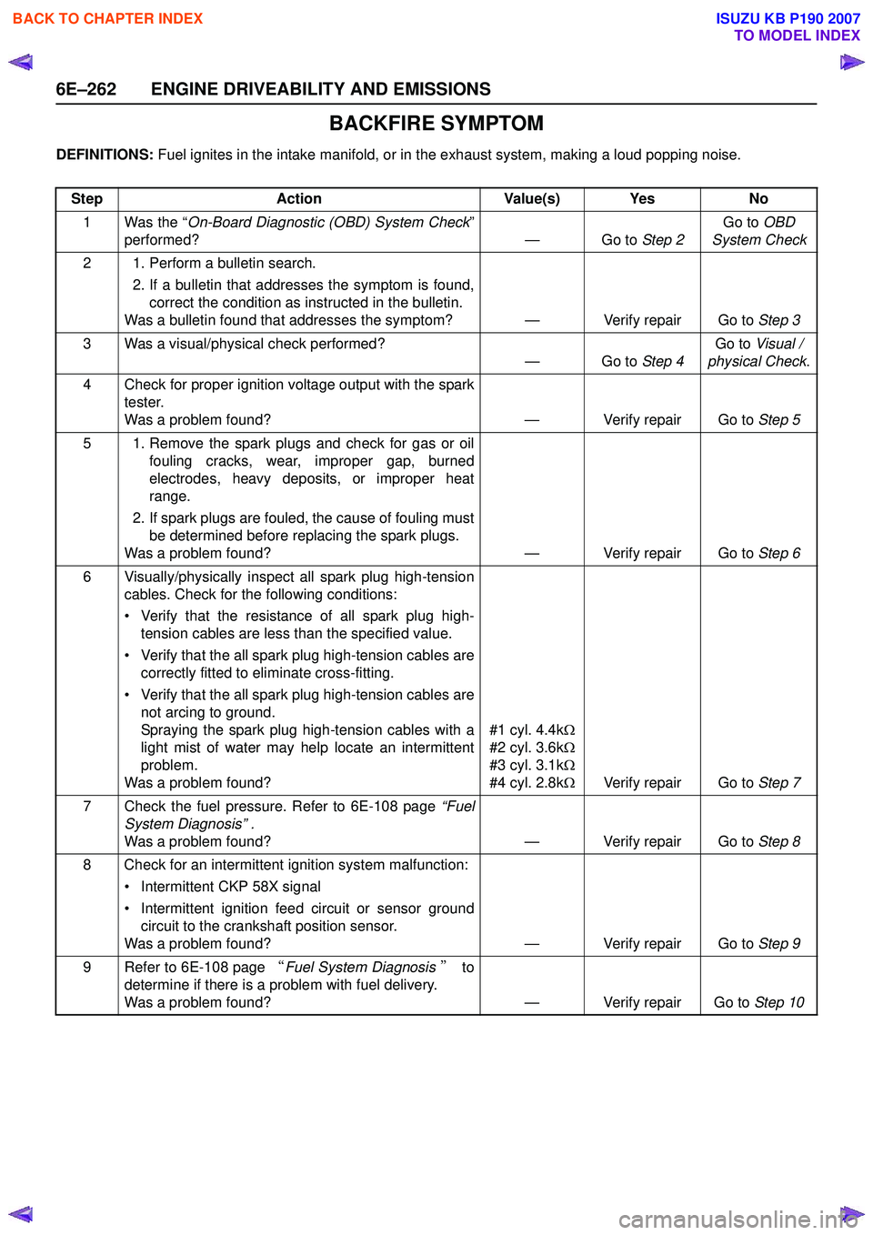
BACKFIRE SYMPTOM
DEFINITIONS: Fuel ignites in the intake manifold, or in the exhaust system, making a loud popping noise.
Step Action Value(s) Yes No
1 Was the “ On-Board Diagnostic (OBD) System Check ”
performed? — Go to Step 2Go to
OBD
System Check
2 1. Perform a bulletin search. 2. If a bulletin that addresses the symptom is found,correct the condition as instructed in the bulletin.
Was a bulletin found that addresses the symptom? — Verify repair Go to Step 3
3 Was a visual/physical check performed? —Go to Step 4Go to
Visual /
physical Check .
4 Check for proper ignition voltage output with the spark tester.
Was a problem found? — Verify repair Go to Step 5
5 1. Remove the spark plugs and check for gas or oil fouling cracks, wear, improper gap, burned
electrodes, heavy deposits, or improper heat
range.
2. If spark plugs are fouled, the cause of fouling must be determined before replacing the spark plugs.
Was a problem found? — Verify repair Go to Step 6
6 Visually/physically inspect all spark plug high-tension cables. Check for the following conditions:
• Verify that the resistance of all spark plug high- tension cables are less than the specified value.
• Verify that the all spark plug high-tension cables are correctly fitted to eliminate cross-fitting.
• Verify that the all spark plug high-tension cables are not arcing to ground.
Spraying the spark plug high-tension cables with a
light mist of water may help locate an intermittent
problem.
Was a problem found? #1 cyl. 4.4k
Ω
#2 cyl. 3.6k Ω
#3 cyl. 3.1k Ω
#4 cyl. 2.8k ΩVerify repair Go to Step 7
7 Check the fuel pressure. Refer to 6E-108 page “Fuel
System Diagnosis” .
Was a problem found? — Verify repair Go to Step 8
8 Check for an intermittent ignition system malfunction: • Intermittent CKP 58X signal
• Intermittent ignition feed circuit or sensor ground circuit to the crankshaft position sensor.
Was a problem found? — Verify repair Go to Step 9
9 Refer to 6E-108 page “Fuel System Diagnosis ” to
determine if there is a problem with fuel delivery.
Was a problem found? — Verify repair Go to Step 10
BACK TO CHAPTER INDEX
TO MODEL INDEX
ISUZU KB P190 2007
Page 2434 of 6020
6E–264 ENGINE DRIVEABILITY AND EMISSIONS
ON-VEHICLE SERVICE PROCEDURE
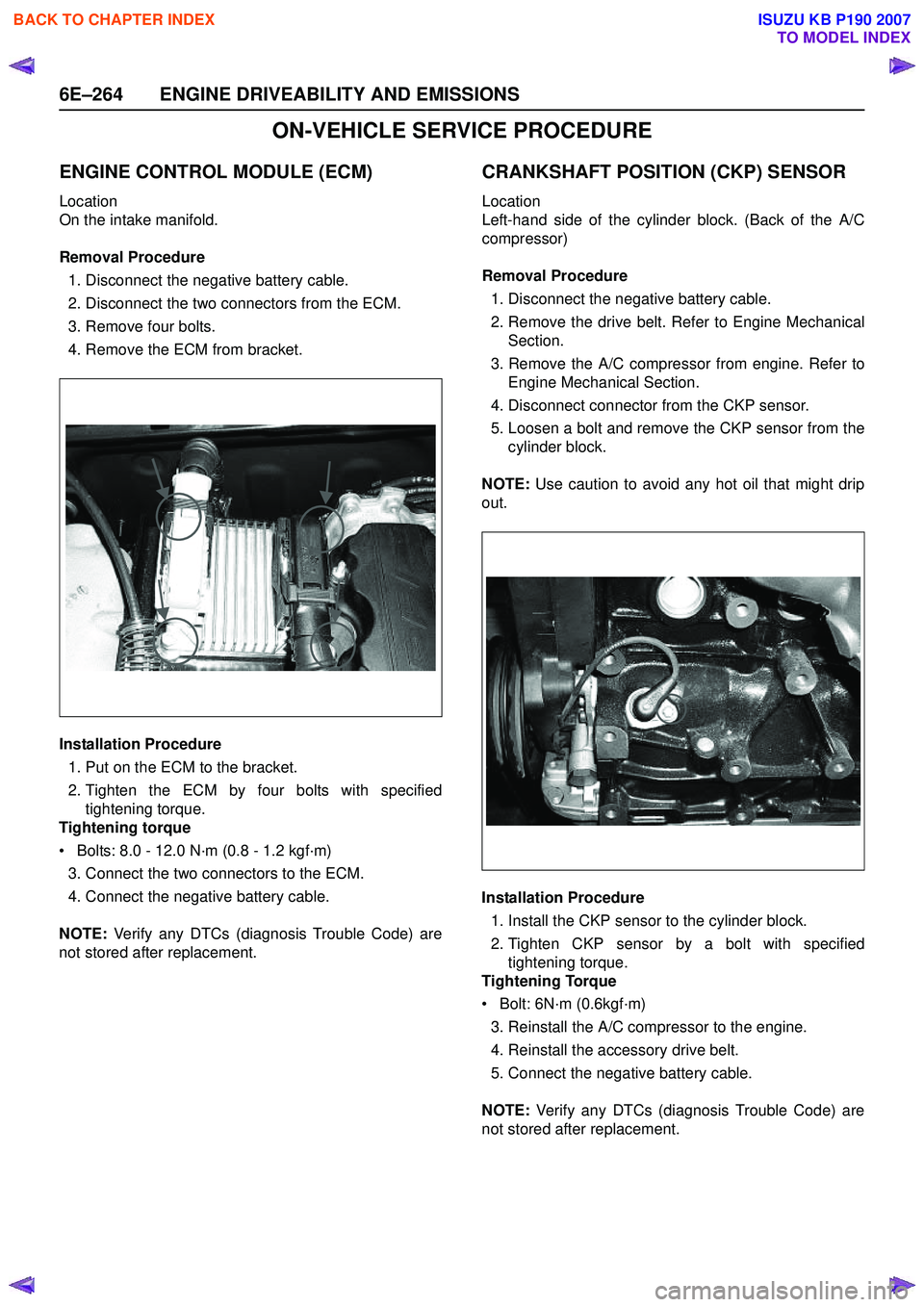
ENGINE CONTROL MODULE (ECM)
Location
On the intake manifold.
Removal Procedure 1. Disconnect the negative battery cable.
2. Disconnect the two connectors from the ECM.
3. Remove four bolts.
4. Remove the ECM from bracket.
Installation Procedure 1. Put on the ECM to the bracket.
2. Tighten the ECM by four bolts with specified tightening torque.
Tightening torque
• Bolts: 8.0 - 12.0 N·m (0.8 - 1.2 kgf·m) 3. Connect the two connectors to the ECM.
4. Connect the negative battery cable.
NOTE: Verify any DTCs (diagnosis Trouble Code) are
not stored after replacement.
CRANKSHAFT POSITION (CKP) SENSOR
Location
Left-hand side of the cylinder block. (Back of the A/C
compressor)
Removal Procedure 1. Disconnect the negative battery cable.
2. Remove the drive belt. Refer to Engine Mechanical Section.
3. Remove the A/C compressor from engine. Refer to Engine Mechanical Section.
4. Disconnect connector from the CKP sensor.
5. Loosen a bolt and remove the CKP sensor from the cylinder block.
NOTE: Use caution to avoid any hot oil that might drip
out.
Installation Procedure 1. Install the CKP sensor to the cylinder block.
2. Tighten CKP sensor by a bolt with specified tightening torque.
Tightening Torque
• Bolt: 6N·m (0.6kgf·m)
3. Reinstall the A/C compressor to the engine.
4. Reinstall the accessory drive belt.
5. Connect the negative battery cable.
NOTE: Verify any DTCs (diagnosis Trouble Code) are
not stored after replacement.
BACK TO CHAPTER INDEX
TO MODEL INDEX
ISUZU KB P190 2007
Page 2435 of 6020

ENGINE DRIVEABILITY AND EMISSIONS 6E–265
ENGINE COOLANT TEMPERATURE (ECT)
SENSOR
Location
Installed to the thermostat housing.
Removal Procedure 1. Disconnect the negative battery cable.
2. Drain enough engine coolant so that the coolant level will be below the ECT sensor.
3. Disconnect connector from the ECT sensor.
4. Loosen and remove the ECT sensor from the thermostat housing.
NOTE: Cool down the engine before above procedures
are carried out.
Installation Procedure
1. Apply sealer to threads of screw at the ECT sensor.
2. Tighten the ECT sensor with specified tightening torque.
Tightening Torque
• Bolt: 13N·m (1.3kgf·m)
3. Connect a ECT sensor connector to the ECT sensor.
4. Fill the engine coolant.
5. Connect the negative battery cable.
NOTE: Verify any DTCs (diagnosis Trouble Code) are
not stored after replacement.
Verify no engine coolant leaking from the sensor
threads after replacement.
INTAKE AIR TEMPERATURE (IAT) SENSOR
Location
Installed to the intake duct housing.
Removal Procedure 1. Disconnect the negative battery cable.
2. Disconnect a IAT sensor connector from the IAT sensor.
3. Remove the IAT sensor from the intake duct.
Installation Procedure 1. Install the IAT sensor into intake air duct.
2. Connect a IAT sensor connector to the IAT sensor.
3. Connect the negative battery cable.
NOTE: Verify any DTCs (diagnosis Trouble Code) are
not stored after replacement.
BACK TO CHAPTER INDEX
TO MODEL INDEX
ISUZU KB P190 2007
Page 2436 of 6020
6E–266 ENGINE DRIVEABILITY AND EMISSIONS
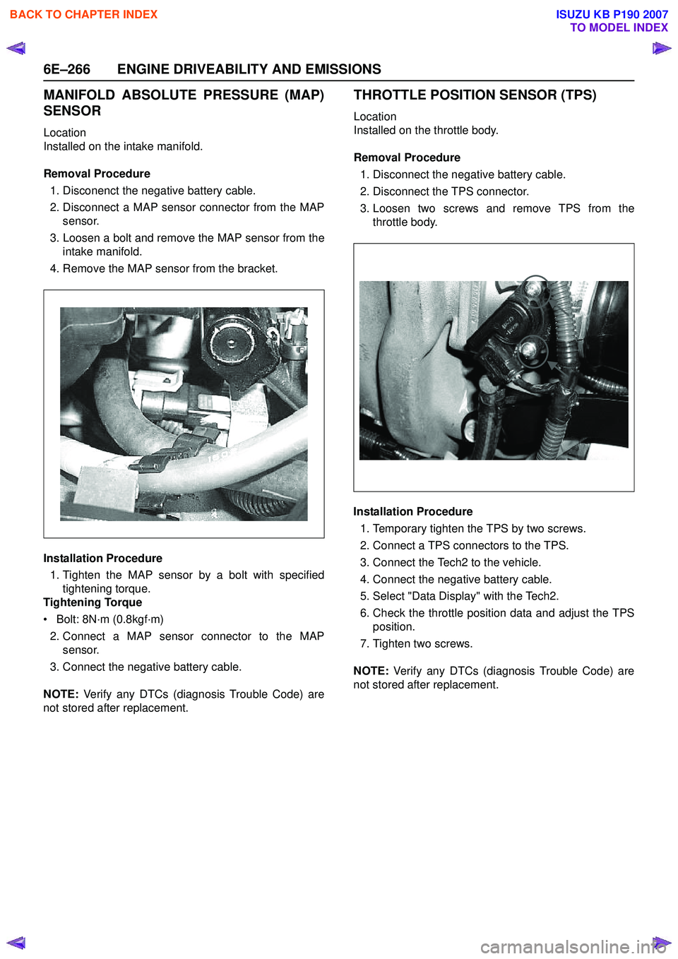
MANIFOLD ABSOLUTE PRESSURE (MAP)
SENSOR
Location
Installed on the intake manifold.
Removal Procedure 1. Disconenct the negative battery cable.
2. Disconnect a MAP sensor connector from the MAP sensor.
3. Loosen a bolt and remove the MAP sensor from the intake manifold.
4. Remove the MAP sensor from the bracket.
Installation Procedure 1. Tighten the MAP sensor by a bolt with specified tightening torque.
Tightening Torque
• Bolt: 8N·m (0.8kgf·m) 2. Connect a MAP sensor connector to the MAP sensor.
3. Connect the negative battery cable.
NOTE: Verify any DTCs (diagnosis Trouble Code) are
not stored after replacement.
THROTTLE POSITION SENSOR (TPS)
Location
Installed on the throttle body.
Removal Procedure 1. Disconnect the negative battery cable.
2. Disconnect the TPS connector.
3. Loosen two screws and remove TPS from the throttle body.
Installation Procedure 1. Temporary tighten the TPS by two screws.
2. Connect a TPS connectors to the TPS.
3. Connect the Tech2 to the vehicle.
4. Connect the negative battery cable.
5. Select "Data Display" with the Tech2.
6. Check the throttle position data and adjust the TPS position.
7. Tighten two screws.
NOTE: Verify any DTCs (diagnosis Trouble Code) are
not stored after replacement.
BACK TO CHAPTER INDEX
TO MODEL INDEX
ISUZU KB P190 2007