sensor ISUZU KB P190 2007 Workshop Repair Manual
[x] Cancel search | Manufacturer: ISUZU, Model Year: 2007, Model line: KB P190, Model: ISUZU KB P190 2007Pages: 6020, PDF Size: 70.23 MB
Page 2675 of 6020

Engine Mechanical – V6 Page 6A1–196
61 Remove the air cleaner cover assembly including the
MAF sensor assembly (1).
62 Remove the air cleaner filter (2) from the air cleaner body assembly (3).
Figure 6A1 – 348
63 Disconnect the ECM connectors (1).
Figure 6A1 – 349
64 Disconnect the canister hose (1).
Figure 6A1 – 350
BACK TO CHAPTER INDEX
TO MODEL INDEX
ISUZU KB P190 2007
Page 2676 of 6020

Engine Mechanical – V6 Page 6A1–197
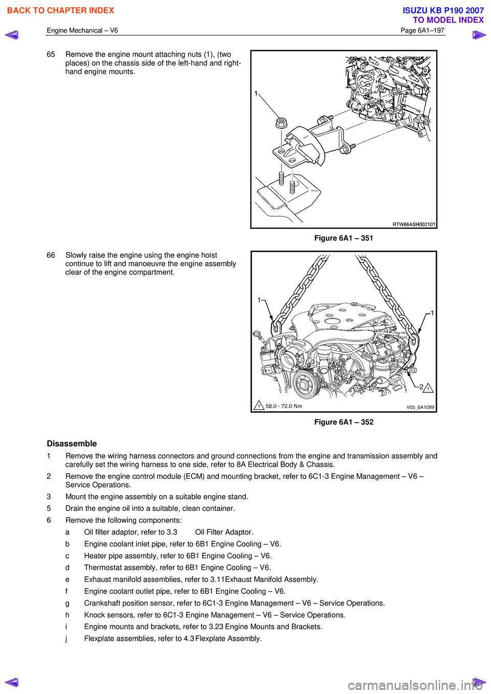
65 Remove the engine mount attaching nuts (1), (two
places) on the chassis side of the left-hand and right-
hand engine mounts.
Figure 6A1 – 351
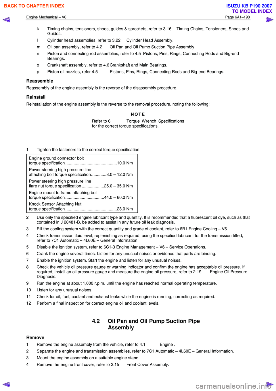
66 Slowly raise the engine using the engine hoist continue to lift and manoeuvre the engine assembly
clear of the engine compartment.
Figure 6A1 – 352
Disassemble
1 Remove the wiring harness connectors and ground connections from the engine and transmission assembly and carefully set the wiring harness to one side, refer to 8A Electrical Body & Chassis.
2 Remove the engine control module (ECM) and mounting bracket, refer to 6C1-3 Engine Management – V6 – Service Operations.
3 Mount the engine assembly on a suitable engine stand.
5 Drain the engine oil into a suitable, clean container.
6 Remove the following components: a Oil filter adaptor, refer to 3.3 Oil Filter Adaptor.
b Engine coolant inlet pipe, refer to 6B1 Engine Cooling – V6.
c Heater pipe assembly, refer to 6B1 Engine Cooling – V6.
d Thermostat assembly, refer to 6B1 Engine Cooling – V6.
e Exhaust manifold assemblies, refer to 3.11Exhaust Manifold Assembly.
f Engine coolant outlet pipe, refer to 6B1 Engine Cooling – V6.
g Crankshaft position sensor, refer to 6C1-3 Engine Management – V6 – Service Operations.
h Knock sensors, refer to 6C1-3 Engine Management – V6 – Service Operations.
i Engine mounts and brackets, refer to 3.23 Engine Mounts and Brackets.
j Flexplate assemblies, refer to 4.3 Flexplate Assembly.
BACK TO CHAPTER INDEX
TO MODEL INDEX
ISUZU KB P190 2007
Page 2677 of 6020

Engine Mechanical – V6 Page 6A1–198
k Timing chains, tensioners, shoes, guides & sprockets, refer to 3.16 Timing Chains, Tensioners, Shoes and
Guides.
l Cylinder head assemblies, refer to 3.22 Cylinder Head Assembly.
m Oil pan assembly, refer to 4.2 Oil Pan and Oil Pump Suction Pipe Assembly.
n Piston and connecting rod assemblies, refer to 4.5 Pistons, Pins, Rings, Connecting Rods and Big-end Bearings.
o Crankshaft assembly, refer to 4.6 Crankshaft and Main Bearings.
p Piston oil nozzles, refer 4.5 Pistons, Pins, Rings, Connecting Rods and Big-end Bearings.
Reassemble
Reassembly of the engine assembly is the reverse of the disassembly procedure.
Reinstall
Reinstallation of the engine assembly is the reverse to the removal procedure, noting the following:
NOTE
Refer to 6 Torque Wrench Specifications
for the correct torque specifications.
1 Tighten the fasteners to the correct torque specification.
Engine ground connector bolt
torque specification ............................................10.0 Nm
Power steering high pressure line
attaching bolt torque specification .............8.0 – 12.0 Nm
Power steering high pressure line
flare nut torque specification ...................25.0 – 35.0 Nm
Engine mount to frame attaching bolt
torque specification .................................44.0 – 60.0 Nm
Knock Sensor Attaching Nut
torque specification ............................................23.0 Nm
2 Use only the specified engine lubricant type and quantity. It is recommended that a fluorescent oil dye, such as that contained in J 28481-B, be added to assist in any future oil leak diagnosis.
3 Fill the cooling system with the correct quantity and grade of coolant, refer to 6B1 Engine Cooling – V6.
4 Check transmission fluid level, replenishing as required, using the specified lubricant for the transmission fitted, refer to 7C1 Automatic – 4L60E – General Information.
5 Disable the ignition system, refer to 6C1-3 Engine Management – V6 – Service Operations.
6 Crank the engine several times. Listen for any unusual noises or evidence that parts are binding.
7 Enable the ignition system. Start the engine and listen for any unusual noises.
8 Check the vehicle oil pressure gauge or warning indicator and confirm the engine has acceptable oil pressure. If required, install an oil pressure gauge and measure the engine oil pressure, refer to 2.19 Engine Oil Pressure
Diagnosis.
9 Run the engine at about 1,000 r.p.m. until the engine has reached normal operating temperature.
10 Listen for any unusual noises.
11 Check for oil, fuel, coolant and exhaust leaks while the engine is running, correcting as required.
12 Perform a final inspection for correct engine oil and coolant levels.
4.2 Oil Pan and Oil Pump Suction Pipe Assembly
Remove
1 Remove the engine assembly from the vehicle, refer to 4.1 Engine .
2 Separate the engine and transmission assemblies, refer to 7C1 Automatic – 4L60E – General Information.
3 Mount the engine assembly on a suitable engine stand.
4 Remove the engine front cover, refer to 3.15 Front Cover Assembly.
BACK TO CHAPTER INDEX
TO MODEL INDEX
ISUZU KB P190 2007
Page 2679 of 6020

Engine Mechanical – V6 Page 6A1–200
Disassemble
1 Remove the following:
2 Oil pan drain plug (7) and sleeve (8).
3 Oil level sensor (9).
4 Crankshaft oil deflector bolts (6) and remove the deflector.
5 Oil pump suction pipe bolts (5) and the suction pipe (3).
6 Oil pump suction pipe gasket (4) from the suction pipe and discard.
Figure 6A1 – 354
Clean
1 Remove any remaining thread sealant, gasket material or sealant using a commercially available wooden or plastic scraper.
2 Clean the oil pan and oil pan components in solvent.
3 Clean out debris from the bolt holes.
Safety glasses must be worn when using
compressed air.
4 Dry the oil pan and oil pan components with compressed air.
BACK TO CHAPTER INDEX
TO MODEL INDEX
ISUZU KB P190 2007
Page 2680 of 6020

Engine Mechanical – V6 Page 6A1–201
Inspect
1 Inspect the exterior of the oil pan for the following
conditions:
• Damage to the drain plug or drain plug hole,
• Damage to the transmission mounting bosses,
• Damage to the oil level sensor threads, and
• Dents or damage to the exterior.
2 Inspect the interior of the oil pan for the following conditions:
• Gouges or damage to the oil pan sealing
surfaces,
• Damage to the crankshaft oil deflector,
• Damage to the bolt holes,
• Damage to the oil suction tube mounting
bosses, and
• Damage to the crankshaft oil deflector mounting
bosses.
Figure 6A1 – 355
3 Inspect the oil pan deflector for damage.
4 Repair or replace the oil pan deflector and/or oil pan as required.
Figure 6A1 – 356
5 Inspect the following:
6 The mounting face (1) of the oil pump suction pipe for possible leakage paths.
7 The oil pump pipe support bracket (2) for cracks or damage.
8 The oil pump suction pipe tube (3) for cracks, imperfections and/or damage.
9 The oil pump screen (4) for blockage, foreign material, tears, cracks and/or damage.
10 Repair or replace the oil pan and/or oil pan components as required.
Figure 6A1 – 357
Reassemble
Reassembly of the oil pan and oil suction pipe assembly is the reverse of the disassembly procedure, noting the
following:
BACK TO CHAPTER INDEX
TO MODEL INDEX
ISUZU KB P190 2007
Page 2681 of 6020

Engine Mechanical – V6 Page 6A1–202
1 Install a new oil suction tube seal onto the oil suction
tube.
2 Install the oil suction pipe and tighten the attaching bolts to the correct torque specification.
Oil suction pipe attaching
bolt torque specification .....................................10.0 Nm
3 Install the crankshaft oil deflector into the oil pan assembly and tighten the attaching bolts to the
correct torque specification.
Crankshaft oil deflector
attaching bolt torque specification ......................10.0 Nm
4 Install the oil level sensor into the oil pan assembly and tighten to the correct torque specification.
Oil level sensor torque specification...................20.0 Nm
Figure 6A1 – 358
5 Install the oil pan drain plug into the oil pan assembly and tighten to the correct torque specification. Oil pan drain plug
torque specification ............................................25.0 Nm
Reinstall
1 Install the guide pins, Tool No. EN-46109 (1) into the oil pan rail bolt hole on each side of the engine block.
Figure 6A1 – 359
2 Place a 3mm bead (1) of RTV sealant on the cylinder block pan rail and crankshaft rear oil seal housing to
oil pan mating surfaces.
3 Position the oil pan onto the cylinder block.
4 Remove the guide pins, Tool No. EN-46109 from the cylinder block.
Figure 6A1 – 360
BACK TO CHAPTER INDEX
TO MODEL INDEX
ISUZU KB P190 2007
Page 2702 of 6020

Engine Mechanical – V6 Page 6A1–223
NOTE
During and after installation, ensure each piston
is positioned correctly in the correct cylinder. The
locating arrow on the top of each piston must be
pointing toward the front of the engine.
6 Repeat these procedures for the remaining piston/connecting rod assemblies.
7 Reinstall the oil pan and oil pump pick up assembly, refer to 4.2 Oil Pan and Oil Pump Suction Pipe Assembly.
8 Reinstall the cylinder heads, refer to 3.22 Cylinder Head Assembly.
9 Reinstall the engine assembly, refer to 4.1 Engine .
4.6 Crankshaft and Main Bearings
1 Remove the engine assembly, refer to 4.1 Engine .
2 Remove both cylinder head assemblies, refer to 3.22 Cylinder Head Assembly.
3 Remove the oil pan assembly, refer to 4.2 Oil Pan and Oil Pump Suction Pipe Assembly.
4 Remove the piston and connecting rod assemblies, refer to 4.5 Pistons, Pins, Rings, Connecting Rods and Big- end Bearings.
5 Remove the oil pump assembly, refer to 3.17 Oil Pump Assembly.
6 Remove the crankshaft rear oil seal and plate assembly, refer to 4.4 Crankshaft Rear Seal and Plate Assembly.
7 Remove the crankshaft position sensor, refer to 6C1-3 Engine Management – V6 – Service Operations.
Crankshaft End Play Measurement
1 Place a dial indicator at the end of the crankshaft nose.
2 Gently force the crankshaft towards the front and rear of the cylinder block with a lever while monitoring the movement of the dial indicator.
3 The crankshaft endplay should not exceed specifications, refer to 5 Specifications.
4 If the specifications are exceeded, inspect the thrust bearing thrust outer diameter and the crankshaft thrust wall for wear and/or excessive runout. Compare the values with the specifications, refer to 5 Specifications.
5 Replace the thrust bearing or crankshaft as required.
Remove
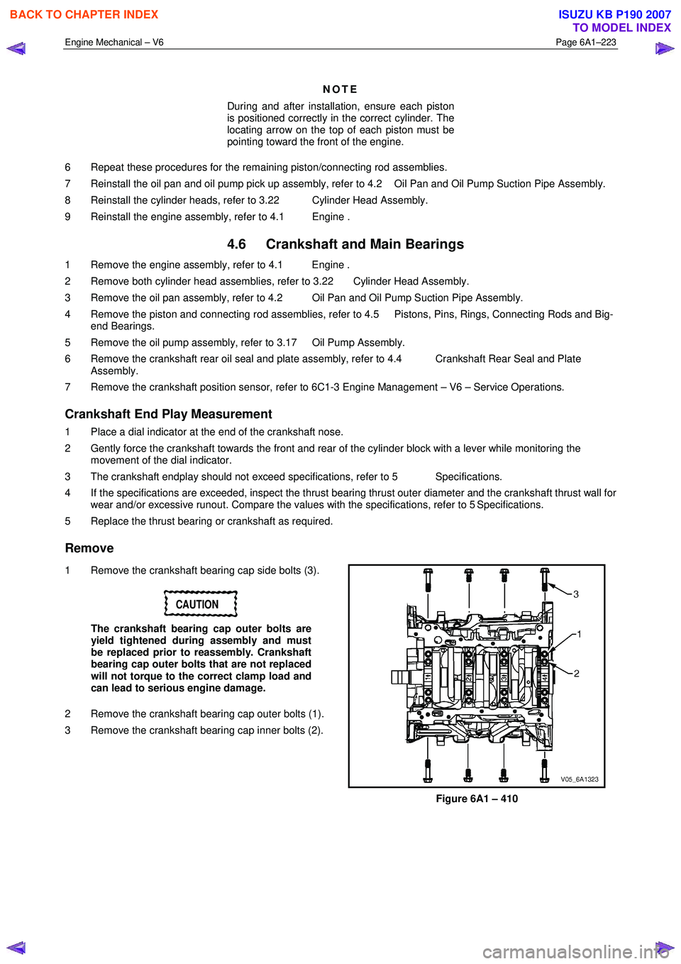
1 Remove the crankshaft bearing cap side bolts (3).
CAUTION
The crankshaft bearing cap outer bolts are
yield tightened during assembly and must
be replaced prior to reassembly. Crankshaft
bearing cap outer bolts that are not replaced
will not torque to the correct clamp load and
can lead to serious engine damage.
2 Remove the crankshaft bearing cap outer bolts (1).
3 Remove the crankshaft bearing cap inner bolts (2).
Figure 6A1 – 410
BACK TO CHAPTER INDEX
TO MODEL INDEX
ISUZU KB P190 2007
Page 2712 of 6020

Engine Mechanical – V6 Page 6A1–233
Crankshaft Final Installation Procedure
1 If removed, install the crankshaft sprocket drive
pin (1). Lightly tap the pin in place with a small soft
face, bronze/plastic, hammer until it bottoms in the
hole.
Figure 6A1 – 432
CAUTION
Ensure the crankshaft position sensor has
been removed from the cylinder block prior
to loading the crankshaft, as damage to the
sensor may occur.
2
Apply a liberal amount of clean engine oil to the upper
and lower bearing surfaces.
3 Gently lower the crankshaft (1) into position in the cylinder block (2).
Figure 6A1 – 433
4 Install the crankshaft main bearing caps.
5 Loosely install the original inner main cap bolts (1).
CAUTION
The outer crankshaft bearing cap bolts (2)
are yield tightened during assembly and
must be replaced prior to reassembly. Outer
crankshaft bearing cap bolts that are not
replaced will not torque to the correct clamp
load and can lead to serious engine damage.
6 Loosely install the new outer main bearing cap bolts (2).
7 Gently tap the crankshaft main bearing caps with a soft-faced hammer to help seat the caps.
Figure 6A1 – 434
BACK TO CHAPTER INDEX
TO MODEL INDEX
ISUZU KB P190 2007
Page 2771 of 6020

Engine Mechanical – V6 Page 6A1–292
6 Torque Wrench Specifications
ATTENTION
�„
�„�„
�„
Fasteners must be replaced after loosening.
Fasteners either have micro encapsulated sealant applied or incorporate a mechanical thread lock and
should only be re-used once. If in doubt, replacement is recommended.
Oil Pan Drain Plug ................................................................................ 25.0 Nm
Oil Filter Adaptor Attaching Bolt ................................................ 20.0 – 26.0 Nm
Oil Level Indicator Tube Attaching Bolt........................................ 8.0 – 12.0 Nm
Accessory Drive Belt Idler Pulley Attaching Bolt................................... 50.0 Nm
Accessory Drive Belt Tensioner Attaching Bolt .................................... 50.0 Nm
Power Steering Reservoir Bracket Attaching Screw.............................. 9.0 Nm
Power Steering Pump Bracket Attaching Bolt ........................... 49.0 – 67.0 Nm
Upper Intake Manifold to Lower Intake Manifold Attaching Bolt ........... 23.0 Nm
Upper Intake Manifold to Cylinder Head Attaching Bolt........................ 23.0 Nm
Lower Intake Manifold to Cylinder Head Attaching Bolt........................ 23.0 Nm
Fuel Injector Wiring Harness Bracket Attaching bolt .............................. 9.0 Nm
Exhaust Manifold to Cylinder Head Attaching Bolt ..................... 17.0 - 23.0 Nm
Exhaust Manifold Heat Shield Attaching Bolt ............................... 8.0 - 12.0 Nm
Battery Harness Ground Terminal Attaching Nut ................................. 13.0 Nm
Camshaft Cover Attaching Bolt ................................................... 8.0 – 12.0 Nm
Engine Ground Connector Bolt............................................................. 10.0 Nm
Engine Wiring Harness Former Attaching Bolt .......................... 12.0 – 16.0 Nm
�„ Crankshaft Balancer Assembly Attaching Bolt:
Stage 1 ..................................................................................... 90.0 –110.0 Nm
Stage 2 ....................................................................................................... 150 °
Engine Front Cover Assembly Attaching Bolt ............................ 20.0 – 26.0 Nm
Camshaft Intermediate Driveshaft Sprocket Attaching Bolt ....... 58.0 – 72.0 Nm
Secondary Timing Chain Guide Attaching Bolt.......................... 20.0 – 26.0 Nm
Secondary Timing Chain Shoe Attaching Bolt ........................... 20.0 – 26.0 Nm
Secondary Timing Chain Tensioner Attaching Bolt ................... 20.0 – 26.0 Nm
Primary Timing Chain Upper Guide Attaching Bolt.................... 20.0 – 26.0 Nm
Primary Timing Chain Tensioner Attaching Bolt ........................ 20.0 – 26.0 Nm
Oil Pump Assembly Attaching Bolt ............................................ 20.0 – 26.0 Nm
Camshaft Sprocket Attaching Bolt ............................................. 49.0 – 67.0 Nm
Exhaust Camshaft Sprocket Attaching Bolt ............................... 49.0 – 67.0 Nm
Camshaft Bearing Cap Attaching Bolt ......................................... 8.0 – 12.0 Nm
Cylinder Head Threaded Plug .............................................................. 31.0 Nm
�„ Cylinder Head M11 Attaching Bolt:
Stage 1 ...................................................................................... 40.0 – 50.0 Nm
Stage 2 ....................................................................................................... 120 °
�„ Cylinder Head M8 Attaching Bolt:
Stage 1 ...................................................................................... 12.0 – 18.0 Nm
Stage 2 ......................................................................................................... 60 °
Engine Mount Bracket to Cylinder Block Attaching Bolt ............ 43.0 – 57.0 Nm
Engine Mount to Bracket Attaching Nut ..................................... 70.0 – 90.0 Nm
Engine Mount to Frame Attaching Nut....................................... 44.0 – 60.0 Nm
Engine Lift Bracket Attaching Bolt .......................................... 58.0 – 72.0.0 Nm
Knock Sensor Attaching Nut................................................................. 23.0 Nm
BACK TO CHAPTER INDEX
TO MODEL INDEX
ISUZU KB P190 2007
Page 2772 of 6020

Engine Mechanical – V6 Page 6A1–293
Power Steering High Pressure Line Attaching Bolt ..................... 8.0 – 12.0 Nm
Power Steering High Pressure Line Flare Nut ........................... 25.0 – 35.0 Nm
Steering Gear Housing Mounting Nut:
Stage 1 ................................................................................................. 60.0 Nm
Stage 2 ................................................................................................40° – 50°
Oil Suction Pipe Attaching Bolt ............................................................. 10.0 Nm
Crankshaft Oil Deflector Attaching bolt................................................. 10.0 Nm
Oil Level Sensor ................................................................................... 20.0 Nm
Oil Pan to Cylinder Block Attaching Bolt .................................... 20.0 – 26.0 Nm
Oil Pan to Crankshaft Rear Oil Seal Housing Attaching Bolt ........ 8.0 - 12.0 Nm
�„ Flexplate Attaching Bolt:
Stage 1 ...................................................................................... 26.0 – 34.0 Nm
Stage 2 ......................................................................................................... 45 °
Crankshaft Rear Oil Seal Housing Attaching Bolt........................ 8.0 – 12.0 Nm
�„ Connecting Rod Cap Attaching Bolt:
Stage 1 ................................................................................................. 30.0 Nm
Stage 2 ................................................................................ Loosen Completely
Stage 3 ................................................................................................. 25.0 Nm
Stage 4 ....................................................................................................... 110 °
Crankshaft Bearing Cap Remover Nut ................................................. 11.0 Nm
�„ Crankshaft Main Bearing Cap Inboard Attaching Bolt:
Stage 1 ................................................................................................. 20.0 Nm
Stage 2 ......................................................................................................... 80 °
�„ Crankshaft Main Bearing Cap Outboard Attaching Bolt:
Stage 1 ................................................................................................. 15.0 Nm
Stage 2 ....................................................................................................... 110 °
�„ Crankshaft main Bearing Cap Side Attaching Bolt:
Stage 1 ................................................................................................. 30.0 Nm
Stage 2 ......................................................................................................... 60 °
Cylinder Block Threaded Plug .................................................... 27.0 - 35.0 Nm
Oil Jet Attaching Bolt ................................................................... 8.0 – 12.0 Nm
BACK TO CHAPTER INDEX
TO MODEL INDEX
ISUZU KB P190 2007