sensor ISUZU KB P190 2007 Workshop Repair Manual
[x] Cancel search | Manufacturer: ISUZU, Model Year: 2007, Model line: KB P190, Model: ISUZU KB P190 2007Pages: 6020, PDF Size: 70.23 MB
Page 2559 of 6020

Engine Mechanical – V6 Page 6A1–80
6 Remove the bolt (1) attaching the ground connector
(2) to the cylinder head.
7 Fro the left-hand side, disconnect the engine coolant temperature (ECT) sensor wiring connector (3).
8 Unclip the engine wiring harness retaining lugs from the side of the camshaft cover.
Figure 6A1 – 63
9 For the right-hand side, remove the engine wiring harness retaining clip (1) from the engine control
module (ECM) bracket (2).
Figure 6A1 – 64
10 Disconnect the camshaft position (CMP) sensor wiring connector (1).
11 Unclip the engine wiring harness retaining lug (3) from the front of the camshaft cover.
12 Remove the ignition coil assemblies; refer to 6C1-3 Engine Management – V6 – Service Operations.
13 Move the engine wiring harness clear of the camshaft cover.
Figure 6A1 – 65
BACK TO CHAPTER INDEX
TO MODEL INDEX
ISUZU KB P190 2007
Page 2566 of 6020

Engine Mechanical – V6 Page 6A1–87
3.14 Crankshaft Front Seal
Replace
1 Remove the crankshaft balancer assembly, refer to 3.13 Crankshaft Balancer Assembly.
2 Using a flat bladed tool (2) or seal remover, Tool No. E-308, carefully remove the crankshaft front seal (1)
from the front cover.
Figure 6A1 – 81
3 Using crankshaft front seal installer, Tool No. J-29184 (2) and a suitable hammer, install a new crankshaft
front seal (1) until fully seated against the front cover
housing.
4 Install the crankshaft balancer assembly, refer to 3.13 Crankshaft Balancer Assembly.
CAUTION
Do not lubricate the crankshaft front oil seal
or crankshaft balancer sealing surfaces. The
crankshaft balancer is installed into a dry
seal.
Figure 6A1 – 82
3.15 Front Cover Assembly
Remove
1 Drain the engine coolant, refer to 6B1_Engine Cooling.
2 Remove the water outlet pipe and coolant pump assembly, refer to 6B1_ Engine Cooling:
3 Remove the camshaft covers, refer to 3.12 Camshaft Cover.
4 Remove the crankshaft balancer assembly, refer to 3.13 Crankshaft Balancer Assembly.
5 Disconnect the purge vent hose from the water outlet pipe.
NOTE
Do not disconnect the power steering pipes or
drain the power steering fluid.
6 Remove the power steering pump reservoir mounting bracket, refer to 3.8 Power Steering Pump Bracket.
7 Remove the camshaft position sensor, refer to 6C1-3 Engine Management – V6 – Service Operations.
BACK TO CHAPTER INDEX
TO MODEL INDEX
ISUZU KB P190 2007
Page 2620 of 6020
Engine Mechanical – V6 Page 6A1–141
Reassemble
CAUTION
As there are no serviceable components
within the oil pump, a disassembled oil pump
must be replaced.
Reinstall
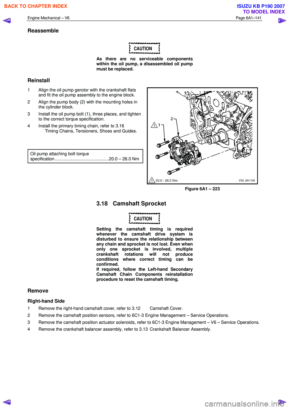
1 Align the oil pump gerotor with the crankshaft flats and fit the oil pump assembly to the engine block.
2 Align the pump body (2) with the mounting holes in the cylinder block.
3 Install the oil pump bolt (1), three places, and tighten to the correct torque specification.
4 Install the primary timing chain, refer to 3.16 Timing Chains, Tensioners, Shoes and Guides.
Oil pump attaching bolt torque
specification ............................................20.0 – 26.0 Nm
Figure 6A1 – 223
3.18 Camshaft Sprocket
CAUTION
Setting the camshaft timing is required
whenever the camshaft drive system is
disturbed to ensure the relationship between
any chain and sprocket is not lost. Even when
only one sprocket is involved, multiple
crankshaft rotations will not produce
conditions where correct timing can be
confirmed.
If required, follow the Left-hand Secondary
Camshaft Chain Components reinstallation
procedure to reset the camshaft timing.
Remove
Right-hand Side
1 Remove the right-hand camshaft cover, refer to 3.12 Camshaft Cover.
2 Remove the camshaft position sensors, refer to 6C1-3 Engine Management – Service Operations.
3 Remove the camshaft position actuator solenoids, refer to 6C1-3 Engine Management – V6 – Service Operations.
4 Remove the crankshaft balancer assembly, refer to 3.13 Crankshaft Balancer Assembly.
BACK TO CHAPTER INDEX
TO MODEL INDEX
ISUZU KB P190 2007
Page 2623 of 6020
Engine Mechanical – V6 Page 6A1–144
Left-hand Side
1 Remove the left-hand camshaft cover, refer to 3.12 Camshaft Cover.
2 Remove the camshaft position sensors, refer to 6C1-3 Engine Management – V6 – Service Operations.
3 Remove the camshaft position actuator solenoids, refer to 6C1-3 Engine Management – V6 – Service Operations.
4 Remove the crankshaft balancer assembly, refer to 3.13 Crankshaft Balancer Assembly.
5 Install the crankshaft rotation socket Tool No. EN-46111 onto the crankshaft.
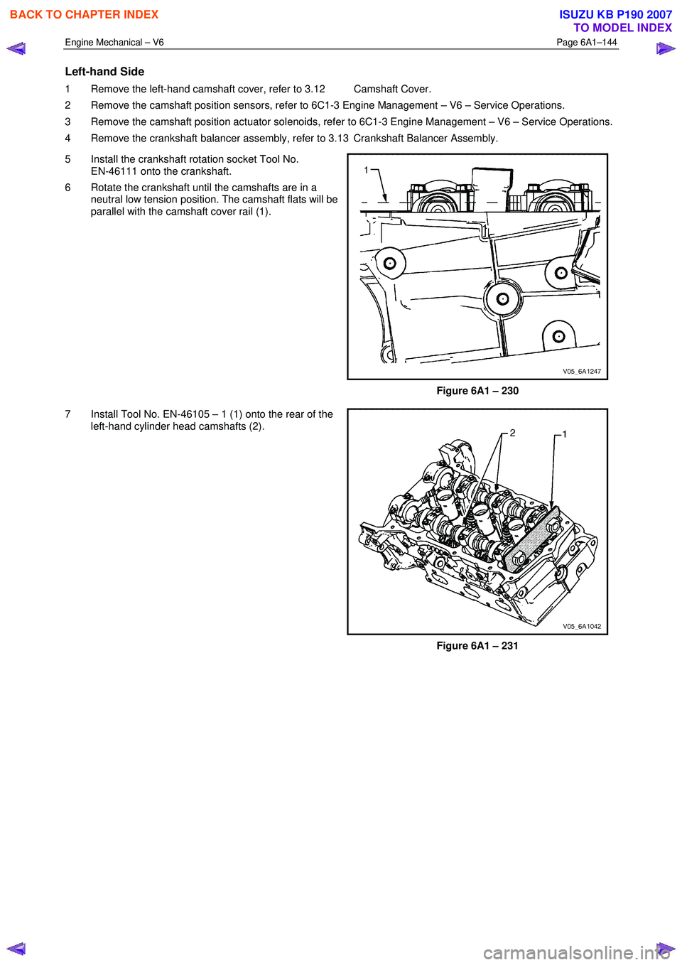
6 Rotate the crankshaft until the camshafts are in a neutral low tension position. The camshaft flats will be
parallel with the camshaft cover rail (1).
Figure 6A1 – 230
7 Install Tool No. EN-46105 – 1 (1) onto the rear of the left-hand cylinder head camshafts (2).
Figure 6A1 – 231
BACK TO CHAPTER INDEX
TO MODEL INDEX
ISUZU KB P190 2007
Page 2641 of 6020
Engine Mechanical – V6 Page 6A1–162
9 Remove and discard the cylinder head gasket (1).
Figure 6A1 – 276
Left-hand Side (Bank 2) Cylinder Head
1 Remove the intake manifold assembly, refer to 3.10 Intake Manifold Assembly – Complete.
2 Remove the exhaust manifold, refer to 3.11 Exhaust Manifold Assembly.
3 Remove the power steering reservoir and pump mounting brackets, refer to 3.8 Power Steering Pump Bracket.
NOTE
Do not disconnect the power steering pipes
and/or hoses.
4 Remove the oil filter adapter upper bolt. NOTE
Do not remove the oil filter adapter.
5 Remove the engine coolant temperature (ECT) sensor, refer to 6C1-3 Engine Management – V6 – Service Operations.
6 Remove engine harness ground terminal attaching bolt from cylinder head, refer to 8A Electrical Body & Chassis.
7 Remove the left-hand bank secondary timing chain, refer to 3.16 Timing Chains, Tensioners, Shoes and Guides.
8 Remove the camshaft position actuators, refer to 3.18 Camshaft Sprocket.
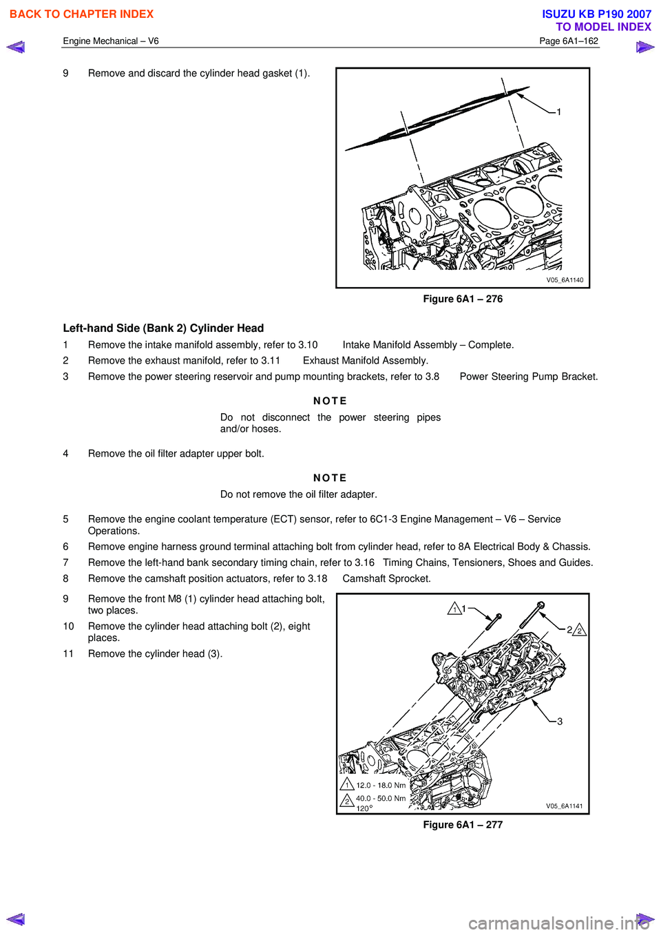
9 Remove the front M8 (1) cylinder head attaching bolt, two places.
10 Remove the cylinder head attaching bolt (2), eight places.
11 Remove the cylinder head (3).
Figure 6A1 – 277
BACK TO CHAPTER INDEX
TO MODEL INDEX
ISUZU KB P190 2007
Page 2664 of 6020
Engine Mechanical – V6 Page 6A1–185
Remove
1 Remove the skid plate.
2 Drain the radiator coolant, refer to 6B1 Engine Cooling – V6.
3 Disconnect the battery negative and positive terminal, refer to 8A Electrical Body & Chassis.
4 Remove the battery from the vehicle.
5 Depressurise the fuel system pressure, refer to 6C Fuel System – V6.
6 Make alignment marks on the bonnet and hinges in order to return the bonnet to the exact original position.
7 Remove the bonnet, refer to 2B Sheet Metal.
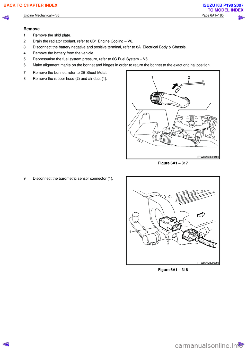
8 Remove the rubber hose (2) and air duct (1).
Figure 6A1 – 317
9 Disconnect the barometric sensor connector (1).
Figure 6A1 – 318
BACK TO CHAPTER INDEX
TO MODEL INDEX
ISUZU KB P190 2007
Page 2668 of 6020
Engine Mechanical – V6 Page 6A1–189
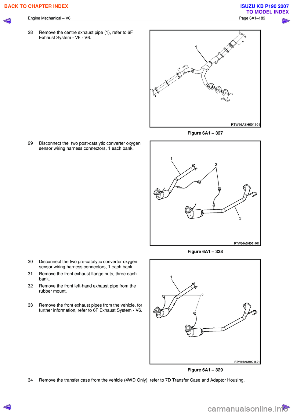
28 Remove the centre exhaust pipe (1), refer to 6F
Exhaust System - V6 - V6.
Figure 6A1 – 327
29 Disconnect the two post-catalytic converter oxygen sensor wiring harness connectors, 1 each bank.
Figure 6A1 – 328
30 Disconnect the two pre-catalytic converter oxygen sensor wiring harness connectors, 1 each bank.
31 Remove the front exhaust flange nuts, three each bank.
32 Remove the front left-hand exhaust pipe from the rubber mount.
33 Remove the front exhaust pipes from the vehicle, for further information, refer to 6F Exhaust System - V6.
Figure 6A1 – 329
34 Remove the transfer case from the vehicle (4W D Only), refer to 7D Transfer Case and Adaptor Housing.
BACK TO CHAPTER INDEX
TO MODEL INDEX
ISUZU KB P190 2007
Page 2670 of 6020

Engine Mechanical – V6 Page 6A1–191
Figure 6A1 – 332
Figure 6A1 – 333 Figure 6A1 – 334
42 Fit the engine lifting brackets (1), (EN–46114) and attach the engine hoist, raise the engine to take the weight off the engine mounts.
Engine Lift Bracket Attaching Bolt
torque specification
.............................................................58.0 – 72.0.0 Nm
43 Remove the left-hand side knock sensor (1).
Figure 6A1 – 335
NOTE
Removal or the starter motor is only required for
vehicles with an Automatic Transmission.
BACK TO CHAPTER INDEX
TO MODEL INDEX
ISUZU KB P190 2007
Page 2671 of 6020
Engine Mechanical – V6 Page 6A1–192
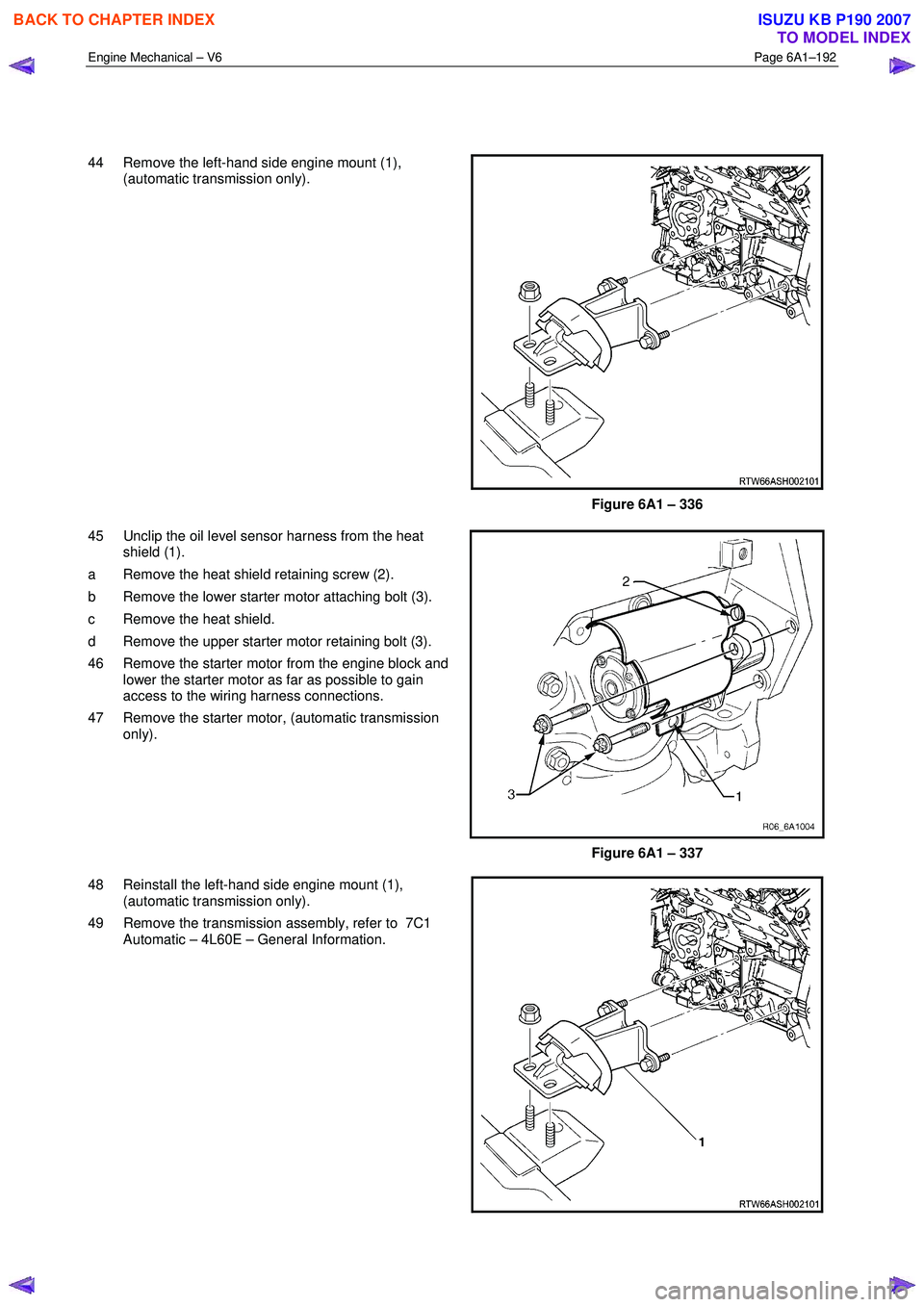
44 Remove the left-hand side engine mount (1), (automatic transmission only).
Figure 6A1 – 336
45 Unclip the oil level sensor harness from the heat shield (1).
a Remove the heat shield retaining screw (2).
b Remove the lower starter motor attaching bolt (3).
c Remove the heat shield.
d Remove the upper starter motor retaining bolt (3).
46 Remove the starter motor from the engine block and lower the starter motor as far as possible to gain
access to the wiring harness connections.
47 Remove the starter motor, (automatic transmission only).
Figure 6A1 – 337
48 Reinstall the left-hand side engine mount (1), (automatic transmission only).
49 Remove the transmission assembly, refer to 7C1 Automatic – 4L60E – General Information.
BACK TO CHAPTER INDEX
TO MODEL INDEX
ISUZU KB P190 2007
Page 2672 of 6020
Engine Mechanical – V6 Page 6A1–193
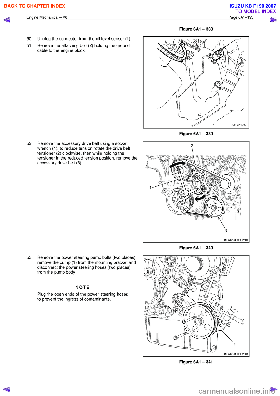
Figure 6A1 – 338
50 Unplug the connector from the oil level sensor (1).
51 Remove the attaching bolt (2) holding the ground cable to the engine block.
Figure 6A1 – 339
52 Remove the accessory drive belt using a socket wrench (1), to reduce tension rotate the drive belt
tensioner (2) clockwise, then while holding the
tensioner in the reduced tension position, remove the
accessory drive belt (3).
Figure 6A1 – 340
53 Remove the power steering pump bolts (two places), remove the pump (1) from the mounting bracket and
disconnect the power steering hoses (two places)
from the pump body.
NOTE
Plug the open ends of the power steering hoses
to prevent the ingress of contaminants.
Figure 6A1 – 341
BACK TO CHAPTER INDEX
TO MODEL INDEX
ISUZU KB P190 2007