sensor ISUZU KB P190 2007 Workshop Repair Manual
[x] Cancel search | Manufacturer: ISUZU, Model Year: 2007, Model line: KB P190, Model: ISUZU KB P190 2007Pages: 6020, PDF Size: 70.23 MB
Page 3565 of 6020
Engine Management – V6 – Service Operations Page 6C1-3–41
Ensure the air intake duct sealing rubber is
correctly positioned on the throttle body.
Failure to do this may result in engine
damage due to unfiltered air entering the
engine intake system.
1 Reinstall the air intake duct and tighten the retaining clamps to the correct torque specification. Air intake duct retaining clamp
torque specification .....................................1.8 – 2.2 Nm
2 Road test the vehicle and check for correct operation, taking particular note that no air leaks are evident.
2.17 Intake Air Temperature Sensor
The intake air temperature (IAT) sensor is part of the mass air flow (MAF) sensor assembly, refer to 2.20 Mass Air
Flow Sensor for the replacement procedure.
Test
To prevent component damage use connector
test adaptor kit J 35616-A.
Resistance Check
Do not use a high temperature heat gun as
damage to the MAF sensor will result.
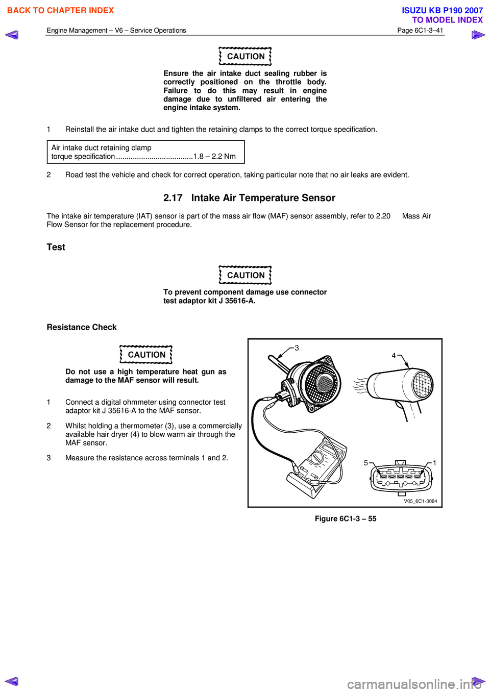
1 Connect a digital ohmmeter using connector test adaptor kit J 35616-A to the MAF sensor.
2 W hilst holding a thermometer (3), use a commercially available hair dryer (4) to blow warm air through the
MAF sensor.
3 Measure the resistance across terminals 1 and 2.
Figure 6C1-3 – 55
BACK TO CHAPTER INDEX
TO MODEL INDEX
ISUZU KB P190 2007
Page 3566 of 6020
Engine Management – V6 – Service Operations Page 6C1-3–42
4 Observe the resistance values as the temperature
increases and compare the temperature / resistance
change to the specifications.
5 If the resistance is not within specifications, replace the MAF sensor.
Intake Air Temperature Vs Resistance
Temperature °C Resistance – Ohms (
Ω)
-40 35140 – 43760
-20 12660 – 15120
-10 7943 – 9307
0 5119 – 5892
20 2290 – 2551
25 1900 – 2100
40 1096 – 1238
60 565 – 654
80 312 – 370
100 184 – 222
120 114 – 141
140 74 – 93
2.18 Knock Sensor, Bank 2 (LHS)
Remove
1 Turn the ignition switch off.
2 Disconnect Bank 2 pre-catalytic converter HO2S wiring harness connector, refer to 2.14 Heated Oxygen Sensor.
3 Raise the front of the vehicle and support on safety stands. Refer to 0A General Information for location of the jacking points.
4 Remove the starter motor heat shield, refer to 6D1-2 Starting System – V6.
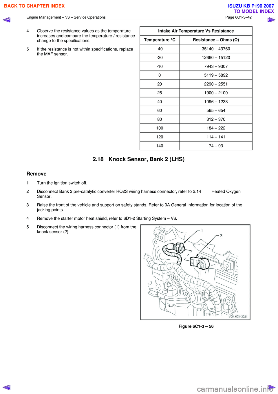
5 Disconnect the wiring harness connector (1) from the knock sensor (2).
Figure 6C1-3 – 56
BACK TO CHAPTER INDEX
TO MODEL INDEX
ISUZU KB P190 2007
Page 3567 of 6020
Engine Management – V6 – Service Operations Page 6C1-3–43
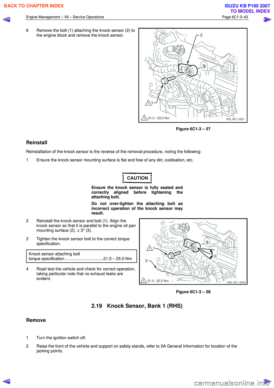
6 Remove the bolt (1) attaching the knock sensor (2) to
the engine block and remove the knock sensor.
Figure 6C1-3 – 57
Reinstall
Reinstallation of the knock sensor is the reverse of the removal procedure, noting the following:
1 Ensure the knock sensor mounting surface is flat and free of any dirt, oxidisation, etc.
Ensure the knock sensor is fully seated and
correctly aligned before tightening the
attaching bolt.
Do not over-tighten the attaching bolt as
incorrect operation of the knock sensor may
result.
2 Reinstall the knock sensor and bolt (1). Align the knock sensor so that it is parallel to the engine oil pan
mounting surface (2), ± 3° (3).
3 Tighten the knock sensor bolt to the correct torque specification.
Knock sensor attaching bolt
torque specification .................................21.0 – 25.0 Nm
4 Road test the vehicle and check for correct operation, taking particular note that no exhaust leaks are
evident.
Figure 6C1-3 – 58
2.19 Knock Sensor, Bank 1 (RHS)
Remove
1 Turn the ignition switch off.
2 Raise the front of the vehicle and support on safety stands, refer to 0A General Information for location of the jacking points.
BACK TO CHAPTER INDEX
TO MODEL INDEX
ISUZU KB P190 2007
Page 3568 of 6020

Engine Management – V6 – Service Operations Page 6C1-3–44
3 Disconnect the wiring harness connector (1) from the
knock sensor (2).
Figure 6C1-3 – 59
4 Remove the bolt (1) attaching the knock sensor (2) to the engine block, and remove the knock sensor.
Figure 6C1-3 – 60
Reinstall
Reinstallation of the knock sensor is the reverse of the removal procedure, noting the following:
1 Ensure the knock sensor mounting surface is flat and free of any dirt, oxidisation, etc.
BACK TO CHAPTER INDEX
TO MODEL INDEX
ISUZU KB P190 2007
Page 3569 of 6020
Engine Management – V6 – Service Operations Page 6C1-3–45
Ensure the knock sensor is fully seated
before tightening the attaching bolt.
Do not over-tighten the attaching bolt as
incorrect operation of the knock sensor may
result.
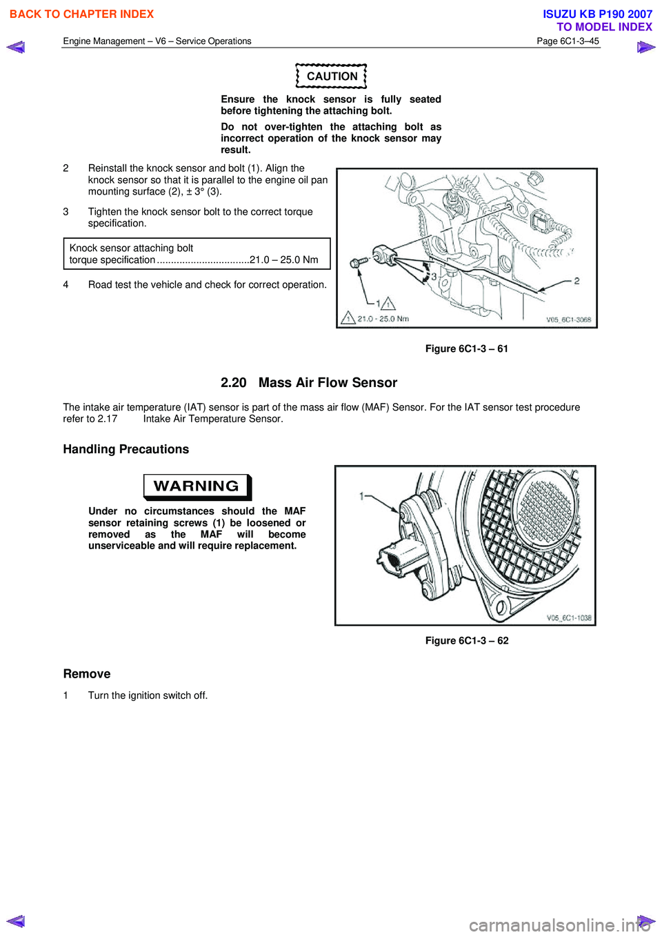
2 Reinstall the knock sensor and bolt (1). Align the knock sensor so that it is parallel to the engine oil pan
mounting surface (2), ± 3° (3).
3 Tighten the knock sensor bolt to the correct torque specification.
Knock sensor attaching bolt
torque specification .................................21.0 – 25.0 Nm
4 Road test the vehicle and check for correct operation.
Figure 6C1-3 – 61
2.20 Mass Air Flow Sensor
The intake air temperature (IAT) sensor is part of the mass air flow (MAF) Sensor. For the IAT sensor test procedure
refer to 2.17 Intake Air Temperature Sensor.
Handling Precautions
Under no circumstances should the MAF
sensor retaining screws (1) be loosened or
removed as the MAF will become
unserviceable and will require replacement.
Figure 6C1-3 – 62
Remove
1 Turn the ignition switch off.
BACK TO CHAPTER INDEX
TO MODEL INDEX
ISUZU KB P190 2007
Page 3570 of 6020
Engine Management – V6 – Service Operations Page 6C1-3–46
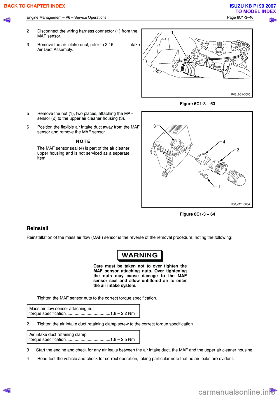
2 Disconnect the wiring harness connector (1) from the
MAF sensor.
3 Remove the air intake duct, refer to 2.16 Intake Air Duct Assembly.
Figure 6C1-3 – 63
5 Remove the nut (1), two places, attaching the MAF sensor (2) to the upper air cleaner housing (3).
6 Position the flexible air intake duct away from the MAF sensor and remove the MAF sensor.
NOTE
The MAF sensor seal (4) is part of the air cleaner
upper housing and is not serviced as a separate
item.
Figure 6C1-3 – 64
Reinstall
Reinstallation of the mass air flow (MAF) sensor is the reverse of the removal procedure, noting the following:
Care must be taken not to over tighten the
MAF sensor attaching nuts. Over tightening
the nuts may cause damage to the MAF
sensor seal and allow unfiltered air to enter
the air intake system.
1 Tighten the MAF sensor nuts to the correct torque specification. Mass air flow sensor attaching nut
torque specification .....................................1.8 – 2.2 Nm
2 Tighten the air intake duct retaining clamp screw to the correct torque specification. Air intake duct retaining clamp
torque specification .....................................1.8 – 2.5 Nm
3 Start the engine and check for any air leaks between the air intake duct, the MAF and the upper air cleaner housing.
4 Road test the vehicle and check for correct operation, taking particular note that no air leaks are evident.
BACK TO CHAPTER INDEX
TO MODEL INDEX
ISUZU KB P190 2007
Page 3579 of 6020
Engine Management – V6 – Service Operations Page 6C1-3–55
Inspect
The following throttle body inspection procedure may be carried out with the throttle body installed on the vehicle. Prior to
performing a throttle body on-vehicle inspection:
• Turn the ignition switch off.
• Disconnect the throttle body wiring harness connector. Refer to Remove in this Section.
• Remove the air intake duct, refer to 2.16 Intake Air Duct Assembly.
To avoid serious personal injury, never
attempt to rotate the throttle plate manually
whilst the throttle body harness connector is
connected to the throttle body.
1 Fully open the throttle plate by hand and inspect the throttle body bore and throttle plate for any deposits.
When cleaning / inspecting the throttle body:
• Do not subject the throttle body assembly
to an immersion cleaner or a strong
solvent. Damage to the throttle position
sensor and / or sealed throttle shaft
bearings will result.
• Never use a wire brush or scraper to clean
the throttle body. A wire brush or sharp
tool may damage the throttle body
components.
2 Use a clean shop towel and a spray type hydro-carbon cleaner to clean the throttle body bore and throttle plate. If necessary, use a parts cleaning brush to remove heavy deposits.
3 Inspect the throttle body for a binding throttle plate by fully opening and closing the throttle plate by hand. It should open and close smoothly.
4 Inspect the throttle body for a bent or damaged throttle plate, cracks, corrosion, or distortion in the throttle body housing.
NOTE
The throttle body contains no serviceable parts
and should not be disassembled. If the throttle
body is damaged it must be replaced as an
assembly.
5 If the throttle body is affected by any of the above conditions, it must be replaced.
6 If an on-vehicle throttle body inspection was performed, perform the following:
• Reinstall the air intake duct, refer to 2.16 Intake Air Duct Assembly.
• Reconnect the throttle body wiring harness connector, refer to Reinstall in this Section.
• Road test the vehicle and check for correct operation, taking particular note that no air leaks are evident.
Reinstall
Reinstallation of the throttle body assembly is the reverse of the removal procedure, noting the following:
1 Ensure the throttle body and upper intake manifold mating surfaces are clean and free of foreign material.
2 Install a new throttle body to upper intake manifold gasket.
BACK TO CHAPTER INDEX
TO MODEL INDEX
ISUZU KB P190 2007
Page 3581 of 6020

Engine Management – V6 – Service Operations Page 6C1-3–57
3 Specifications
Accelerator Pedal Position Sensor 1
Type .....................................................Three wire potentiometer
Accelerator pedal at rest .................................. Less than 1.25 V
Accelerator pedal fully depressed .......................5.0 V maximum
Accelerator Pedal Position Sensor 2
Type .....................................................Three wire potentiometer
Accelerator pedal at rest .................................. Less than 1.25 V
Accelerator pedal fully depressed .......................5.0 V maximum
Camshaft Position (CMP) Sensor
Type ................................... Hall effect, interrupted ring triggered
Air gap ................................................................... 0.1 – 1.8 mm
Air gap adjustment ............................................... No adjustment
Crankshaft Position (CKP) Sensor
Type ....................................................... Inductive magnetic type
Coil resistance @ 20°C .......................................... 850 – 1040 Ω
Air gap ................................................................... 0.1 – 1.5 mm
Air gap adjustment ............................................... No adjustment
Engine Coolant Temperature Sensor
Type .......................................................... Negative temperature
................................................................... coefficient thermistor
Engine Coolant Temperature Vs Resistance
Temperature °C Resistance – Ohms ( Ω)
-40 40490 – 50136
-20 14096 – 16827
-10 8642 – 10152
0 5466 – 6326
20 2351 – 2649
25 1941 – 2173
40 1118 – 1231
60 573 – 618
80 313 – 332
100 182 – 191
120 109 – 116
140 68 – 74
BACK TO CHAPTER INDEX
TO MODEL INDEX
ISUZU KB P190 2007
Page 3582 of 6020

Engine Management – V6 – Service Operations Page 6C1-3–58
Engine Oil Level and Temperature Sensor
Level sensor type ....................................... Magnetic reed switch
Temperature sensor type .......................... Negative temperature
................................................................... coefficient thermistor
Engine Oil Temperature Vs Resistance
Temperature °C Resistance – Ohms ( Ω)
0 7570 – 8000
20 2351 – 2649
30 2225 – 2375
40 1118 – 1231
50 1050 – 1150
80 380 – 470
100 270 – 290
Evaporative Emission (EVAP) Canister Purge Valve
Type .............................................................................. Solenoid
Resistance @ 20°C...................................................... 24 – 28 Ω
Operating voltage................................................... 12.0 – 16.0 V
Engine Firing Order ..................................................................... 1, 2, 3, 4, 5, 6
Fuel Injector
Type .............................................................................. Solenoid
Fuel Injector Resistance @ 20°C ........................... 11.4 – 12.6 Ω
Heated Oxygen Sensor (HO2S) – Four wire
Type ...................................................... Four wire, planar sensor
Operating range (greater than 360°C) .................. 10 – 1000 mV
Closed loop operating range ................................. 300 – 600 mV
Heater resistance @ 20°C ....................................... 8.0 – 10.0 Ω
Heated Oxygen Sensor (HO2S) – Six W ire
Type ....................................... Six wire, wide band planar sensor
Heater resistance @ 20°C ....................................... 8.0 – 10.0 Ω
Intake Air Temperature (IAT) Sensor
Type .......................................................... Negative temperature
.................................................................. Coefficient thermistor
Intake Air Temperature Vs Resistance
Temperature °C Resistance – Ohms ( Ω)
-40 35140 – 43760
-20 12660 – 15120
-10 7943 – 9307
0 5119 – 5892
20 2290 – 2551
25 1900 –2100
40 1096 –1238
60 565 – 654
80 312 – 370
100 184 – 222
120 114 –141
BACK TO CHAPTER INDEX
TO MODEL INDEX
ISUZU KB P190 2007
Page 3583 of 6020

Engine Management – V6 – Service Operations Page 6C1-3–59
Intake Air Temperature Vs Resistance
Temperature °C Resistance – Ohms (Ω)
140 74 –93
Knock Sensor
Type ........................................................ Piezo ceramic element
Mass Air Flow Sensor
Type ......................................................Hot film air-mass sensor
Spark Plug
Type ....................................................................................J gap
Gap ........................................................................ 1.1 – 1.2 mm
Adjustment ........................................................... No adjustment
Throttle Position Sensor 1
Type .....................................................Three wire potentiometer
Closed throttle ................................................. Less than 1.25 V
Wide open throttle ...............................................5.0 V maximum
Throttle Position Sensor 2
Type .....................................................Three wire potentiometer
Closed throttle ................................................. Less than 1.25 V
Wide open throttle ...............................................5.0 V maximum
BACK TO CHAPTER INDEX
TO MODEL INDEX
ISUZU KB P190 2007