sensor ISUZU KB P190 2007 Workshop Repair Manual
[x] Cancel search | Manufacturer: ISUZU, Model Year: 2007, Model line: KB P190, Model: ISUZU KB P190 2007Pages: 6020, PDF Size: 70.23 MB
Page 3756 of 6020
Exhaust System – V6 Page 6F – 8
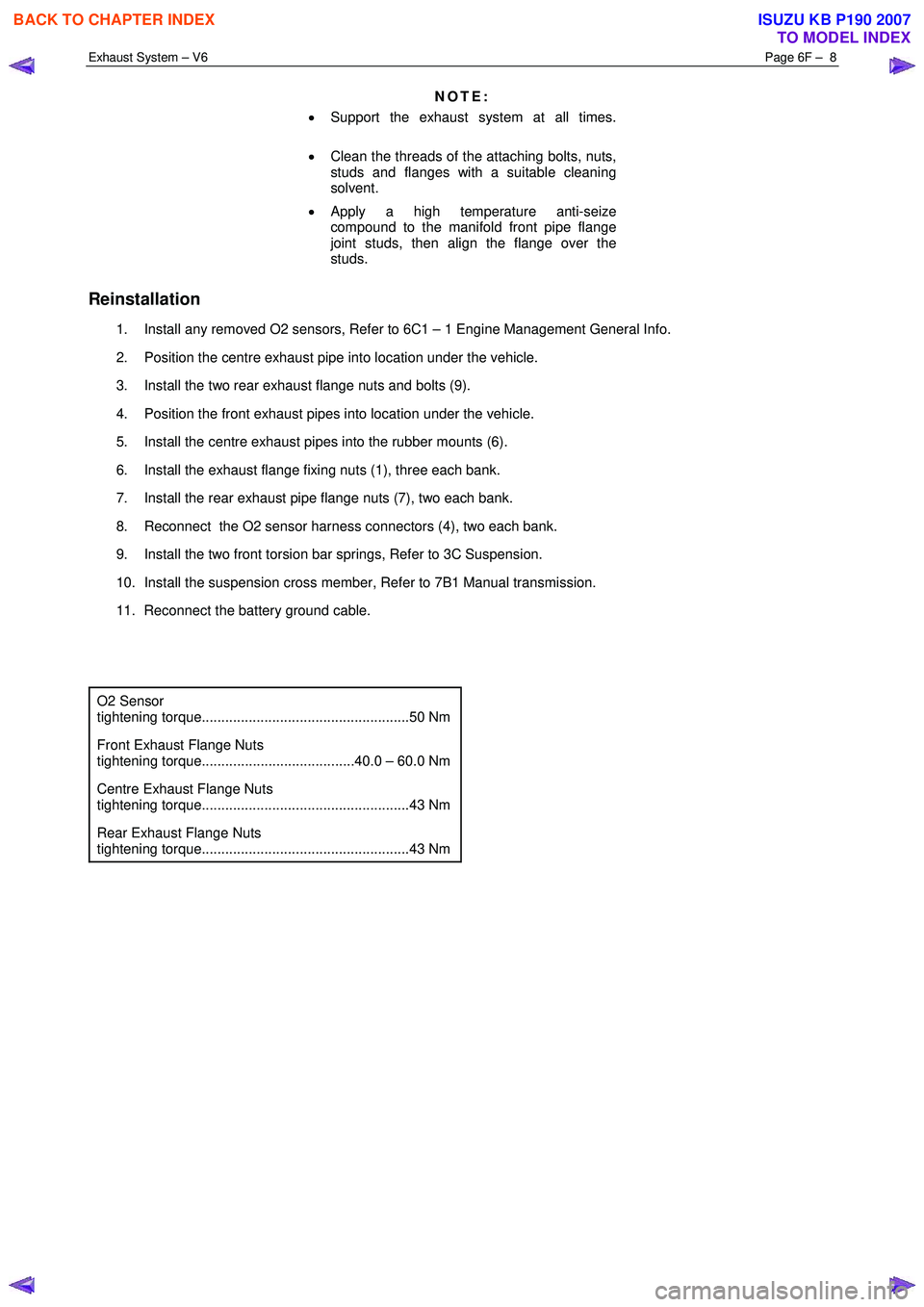
NOTE:
• Support the exhaust system at all times.
• Clean the threads of the attaching bolts, nuts,
studs and flanges with a suitable cleaning
solvent.
• Apply a high temperature anti-seize
compound to the manifold front pipe flange
joint studs, then align the flange over the
studs.
Reinstallation
1. Install any removed O2 sensors, Refer to 6C1 – 1 Engine Management General Info.
2. Position the centre exhaust pipe into location under the vehicle.
3. Install the two rear exhaust flange nuts and bolts (9).
4. Position the front exhaust pipes into location under the vehicle.
5. Install the centre exhaust pipes into the rubber mounts (6).
6. Install the exhaust flange fixing nuts (1), three each bank.
7. Install the rear exhaust pipe flange nuts (7), two each bank.
8. Reconnect the O2 sensor harness connectors (4), two each bank.
9. Install the two front torsion bar springs, Refer to 3C Suspension.
10. Install the suspension cross member, Refer to 7B1 Manual transmission.
11. Reconnect the battery ground cable.
O2 Sensor
tightening torque.....................................................50 Nm
Front Exhaust Flange Nuts
tightening torque.......................................40.0 – 60.0 Nm
Centre Exhaust Flange Nuts
tightening torque.....................................................43 Nm
Rear Exhaust Flange Nuts
tightening torque.....................................................43 Nm
BACK TO CHAPTER INDEX
TO MODEL INDEX
ISUZU KB P190 2007
Page 3758 of 6020
Exhaust System – V6 Page 6F – 10
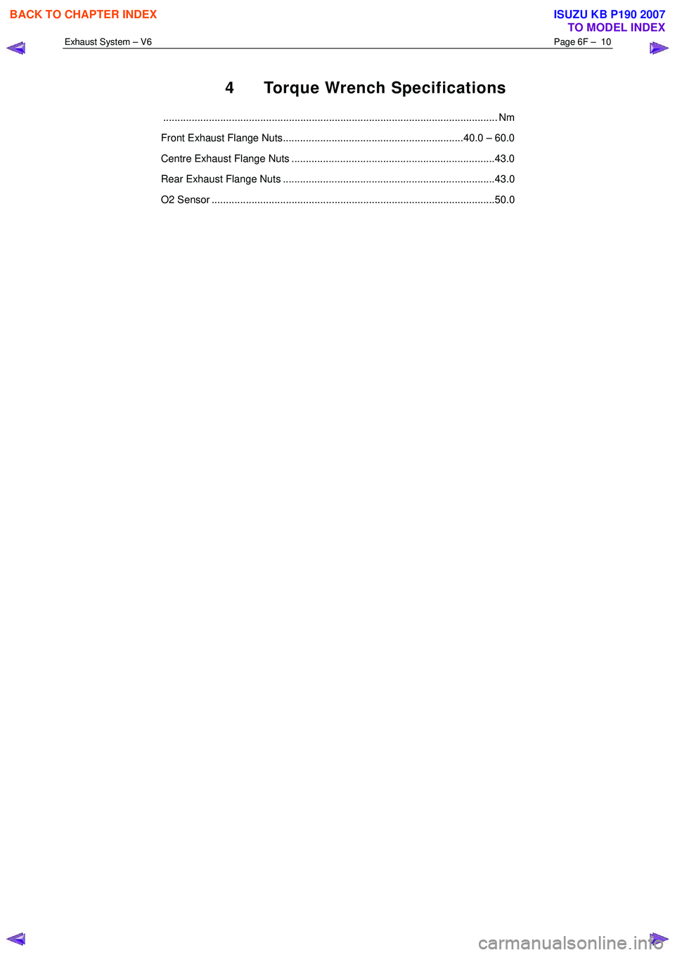
4 Torque Wrench Specifications
..................................................................................................................... Nm
Front Exhaust Flange Nuts...............................................................40.0 – 60.0
Centre Exhaust Flange Nuts .......................................................................43.0
Rear Exhaust Flange Nuts ..........................................................................43.0
O2 Sensor ...................................................................................................50.0
BACK TO CHAPTER INDEX
TO MODEL INDEX
ISUZU KB P190 2007
Page 3761 of 6020
Automatic Transmission – 4L60E – General Information Page 7C1–1
7C1
Automatic Transmission – 4L60E –
General Information
ATTENTION
Before performing any service operation or other procedure described in this Section, refer to Warnings, Cautions and Notes for correct workshop practices with regard to safety and/or property damage.
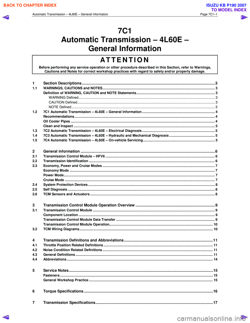
1 Section Descriptions ........................................................................................................... ...................3
1.1 WARNINGS, CAUTIONS and NOTES................................................................................................... ................. 3
Definition of WARNING, CAUTION and NOTE Statements ............................................................................. .... 3
WARNING Defined............................................................................................................................................. 3
CAUTION Defined .............................................................................................................................................. 3
NOTE Defined .................................................................................................................................................... 3
1.2 7C1 Automatic Transmission – 4L60E – General Information ....................................................................... .... 4
Recommendations ................................................................................................................................................. 4
Oil Cooler Pipes ..................................................................................................................................................... 4
Clean and Inspect .............................................................................................................. .................................... 5
1.3 7C2 Automatic Transmission – 4L60E – Electrical Diagnosis ...................................................................... ..... 5
1.4 7C3 Automatic Transmission – 4L60E – Hydraulic and Mechanical Diagnosis ............................................... 5
1.5 7C4 Automatic Transmission – 4L60E – On-vehicle Servicing ...................................................................... .... 5
2 General information ...............................................................................................................................6
2.1 Transmission Control Module – HFV6 ............................................................................................. .................... 6
2.2 Transmission Identification .................................................................................................................................. 6
2.3 Economy, Power and Cruise Modes .................................................................................................................... 7
Economy Mode ...................................................................................................................................................... 7
Power Mode ............................................................................................................................................................ 7
Cruise Mode ........................................................................................................................................................... 7
2.4 System Protection Devices ...................................................................................................... ............................. 8
2.5 Self Diagnosis ........................................................................................................................................................ 8
2.6 TCM Sensors and Actuators ................................................................................................................................. 8
3 Transmission Control Module Operation Overview ...........................................................................9
3.1 Transmission Control Module .............................................................................................................................. 9
Component Location ............................................................................................................. ................................ 9
Transmission Control Module Data Transfer ...................................................................................... ................ 9
Transmission Control Module Operation........................................................................................................... 10
3.2 TCM Wiring Diagrams.......................................................................................................................................... 10
4 Transmission Definitions and Abbreviations ....................................................................................1 1
4.1 Throttle Position Related Definitions ................................................................................................................. 11
4.2 Noise Condition Related Definitions ............................................................................................ ...................... 11
4.3 General Definitions .............................................................................................................................................. 11
4.4 Abbreviations ....................................................................................................................................................... 14
5 Service Notes ........................................................................................................................................15
Fasteners .............................................................................................................................................................. 15
General Workshop Practice ................................................................................................................................ 15
6 Torque Specifications .......................................................................................................... ................16
7 Transmission Specifications.................................................................................................... ...........17
BACK TO CHAPTER INDEX
TO MODEL INDEX
ISUZU KB P190 2007
Page 3768 of 6020
Automatic Transmission – 4L60E – General Information Page 7C1–8
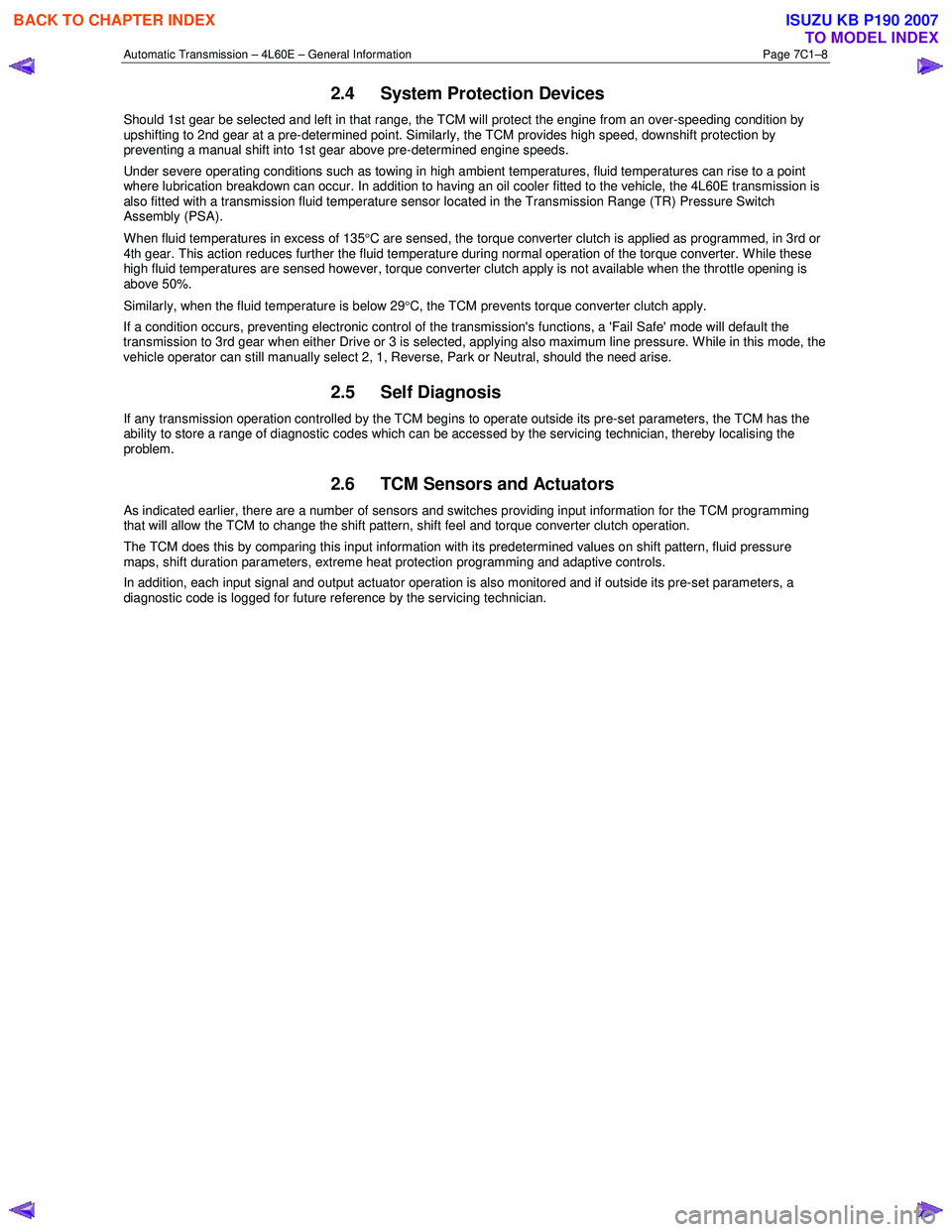
2.4 System Protection Devices
Should 1st gear be selected and left in that range, the TCM will protect the engine from an over-speeding condition by
upshifting to 2nd gear at a pre-determined point. Similarly, the TCM provides high speed, downshift protection by
preventing a manual shift into 1st gear above pre-determined engine speeds.
Under severe operating conditions such as towing in high ambient temperatures, fluid temperatures can rise to a point
where lubrication breakdown can occur. In addition to having an oil cooler fitted to the vehicle, the 4L60E transmission is
also fitted with a transmission fluid temperature sensor located in the Transmission Range (TR) Pressure Switch
Assembly (PSA).
When fluid temperatures in excess of 135 °C are sensed, the torque converter clutch is applied as programmed, in 3rd or
4th gear. This action reduces further the fluid temperature during normal operation of the torque converter. While these
high fluid temperatures are sensed however, torque converter clutch apply is not available when the throttle opening is
above 50%.
Similarly, when the fluid temperature is below 29 °C, the TCM prevents torque converter clutch apply.
If a condition occurs, preventing electronic control of the transmission's functions, a 'Fail Safe' mode will default the
transmission to 3rd gear when either Drive or 3 is selected, applying also maximum line pressure. W hile in this mode, the
vehicle operator can still manually select 2, 1, Reverse, Park or Neutral, should the need arise.
2.5 Self Diagnosis
If any transmission operation controlled by the TCM begins to operate outside its pre-set parameters, the TCM has the
ability to store a range of diagnostic codes which can be accessed by the servicing technician, thereby localising the
problem.
2.6 TCM Sensors and Actuators
As indicated earlier, there are a number of sensors and switches providing input information for the TCM programming
that will allow the TCM to change the shift pattern, shift feel and torque converter clutch operation.
The TCM does this by comparing this input information with its predetermined values on shift pattern, fluid pressure
maps, shift duration parameters, extreme heat protection programming and adaptive controls.
In addition, each input signal and output actuator operation is also monitored and if outside its pre-set parameters, a
diagnostic code is logged for future reference by the servicing technician.
BACK TO CHAPTER INDEX
TO MODEL INDEX
ISUZU KB P190 2007
Page 3769 of 6020
Automatic Transmission – 4L60E – General Information Page 7C1–9
3 Transmission Control Module
Operation Overview
3.1 Transmission Control Module
W ith the introduction of the new HFV6 engine, the powertrain architecture has been redesigned to accommodate this
introduction. W ith this design, a new bus architecture and protocol has also been introduced. The new bus connects the
following modules:
• engine control module (ECM),
• transmission control module (TCM),
• powertrain interface module (PIM) and
• ABS module.
The protocol used to communicate between these modules is called General Motors Local Area Network (GM LAN)
which is based on Controller Area Network (CAN) communication protocol. For further information on GM LAN protocol
and data bus structure, refer to 6E1 Powertrain Interface Module – V6.
Component Location
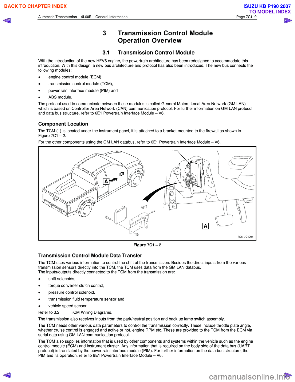
The TCM (1) is located under the instrument panel, it is attached to a bracket mounted to the firewall as shown in
Figure 7C1 – 2.
For the other components using the GM LAN databus, refer to 6E1 Powertrain Interface Module – V6.
Figure 7C1 – 2
Transmission Control Module Data Transfer
The TCM uses various information to control the shift of the transmission. Besides the direct inputs from the various
transmission sensors directly into the TCM, the TCM uses data from the GM LAN databus.
The inputs/outputs directly connected to the TCM from the transmission are:
• shift solenoids,
• torque converter clutch control,
• pressure control solenoid,
• transmission fluid temperature sensor and
• vehicle speed sensor.
Refer to 3.2 TCM Wiring Diagrams.
The transmission also receives inputs from the park/neutral position and back up lamp switch assembly.
The TCM needs other various data parameters to control the transmission correctly. These include throttle plate angle,
whether cruise control is engaged and active or not, engine RPM etc. These are provided to the TCM from the ECM via
serial data using GM LAN communication protocol.
The TCM also supplies information that is used by other components and systems within the vehicle such as the engine
control module (ECM) and instrument cluster. Any information that is required on the body side of the data bus (UART
protocol) is translated by the powertrain interface module (PIM). For further information on the data bus structure, the
PIM and its operation, refer to 6E1 Powertrain Interface Module – V6.
BACK TO CHAPTER INDEX
TO MODEL INDEX
ISUZU KB P190 2007
Page 3770 of 6020
Automatic Transmission – 4L60E – General Information Page 7C1–10
Transmission Control Module Operation
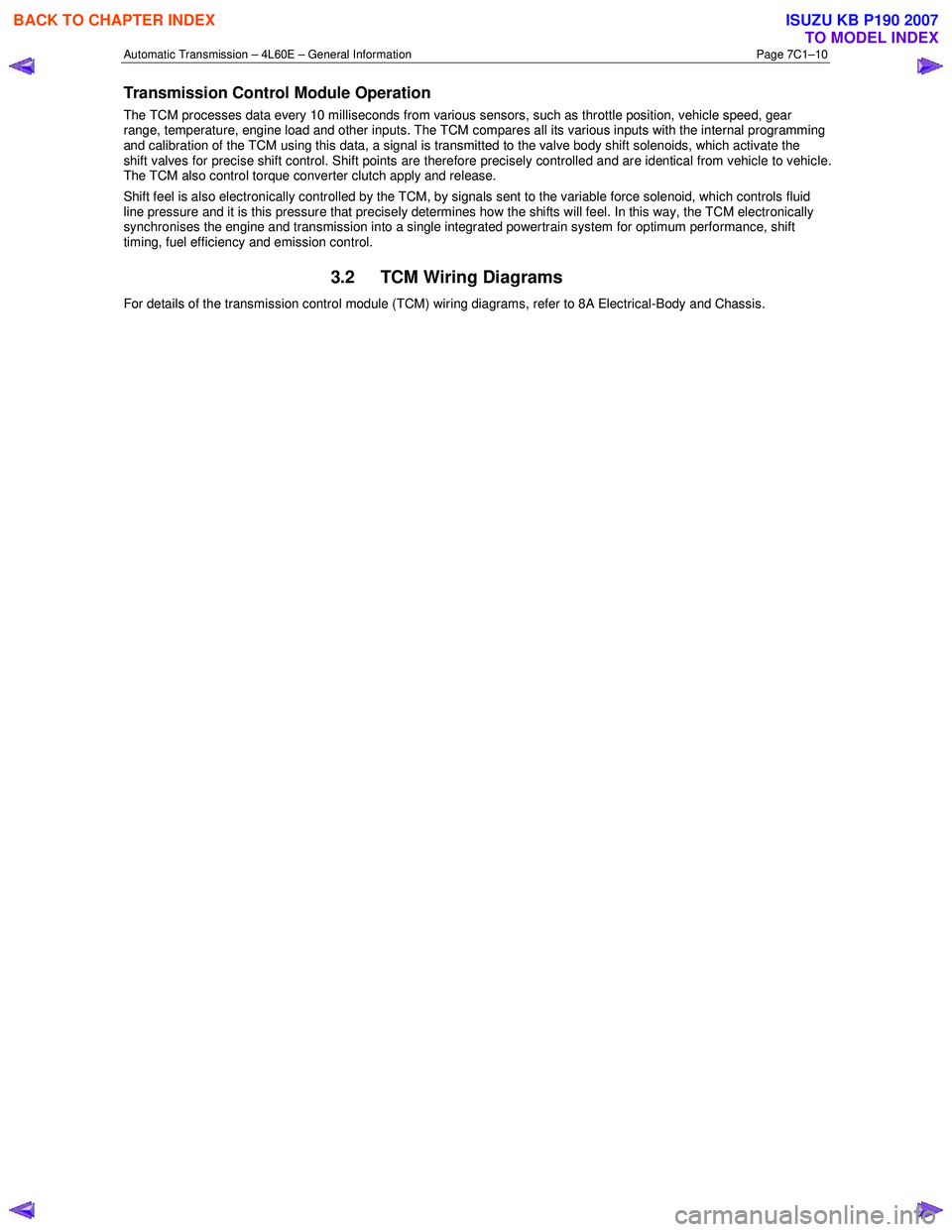
The TCM processes data every 10 milliseconds from various sensors, such as throttle position, vehicle speed, gear
range, temperature, engine load and other inputs. The TCM compares all its various inputs with the internal programming
and calibration of the TCM using this data, a signal is transmitted to the valve body shift solenoids, which activate the
shift valves for precise shift control. Shift points are therefore precisely controlled and are identical from vehicle to vehic le.
The TCM also control torque converter clutch apply and release.
Shift feel is also electronically controlled by the TCM, by signals sent to the variable force solenoid, which controls fluid
line pressure and it is this pressure that precisely determines how the shifts will feel. In this way, the TCM electronically
synchronises the engine and transmission into a single integrated powertrain system for optimum performance, shift
timing, fuel efficiency and emission control.
3.2 TCM Wiring Diagrams
For details of the transmission control module (TCM) wiring diagrams, refer to 8A Electrical-Body and Chassis.
BACK TO CHAPTER INDEX
TO MODEL INDEX
ISUZU KB P190 2007
Page 3774 of 6020
Automatic Transmission – 4L60E – General Information Page 7C1–14
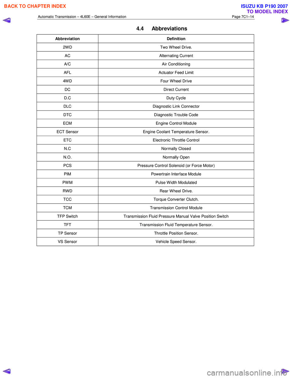
4.4 Abbreviations
Abbreviation Definition
2W D Two W heel Drive.
AC Alternating Current
A/C Air Conditioning
AFL Actuator Feed Limit
4W D Four W heel Drive
DC Direct Current
D.C Duty Cycle
DLC Diagnostic Link Connector
DTC Diagnostic Trouble Code
ECM Engine Control Module
ECT Sensor Engine Coolant Temperature Sensor.
ETC Electronic Throttle Control
N.C Normally Closed
N.O. Normally Open
PCS Pressure Control Solenoid (or Force Motor)
PIM Powertrain Interface Module
PW M Pulse W idth Modulated
RWD Rear Wheel Drive.
TCC Torque Converter Clutch.
TCM Transmission Control Module
TFP Switch Transmission Fluid Pressure Manual Valve Position Switch
TFT Transmission Fluid Temperature Sensor.
TP Sensor Throttle Position Sensor.
VS Sensor Vehicle Speed Sensor.
BACK TO CHAPTER INDEX
TO MODEL INDEX
ISUZU KB P190 2007
Page 3776 of 6020
Automatic Transmission – 4L60E – General Information Page 7C1–16
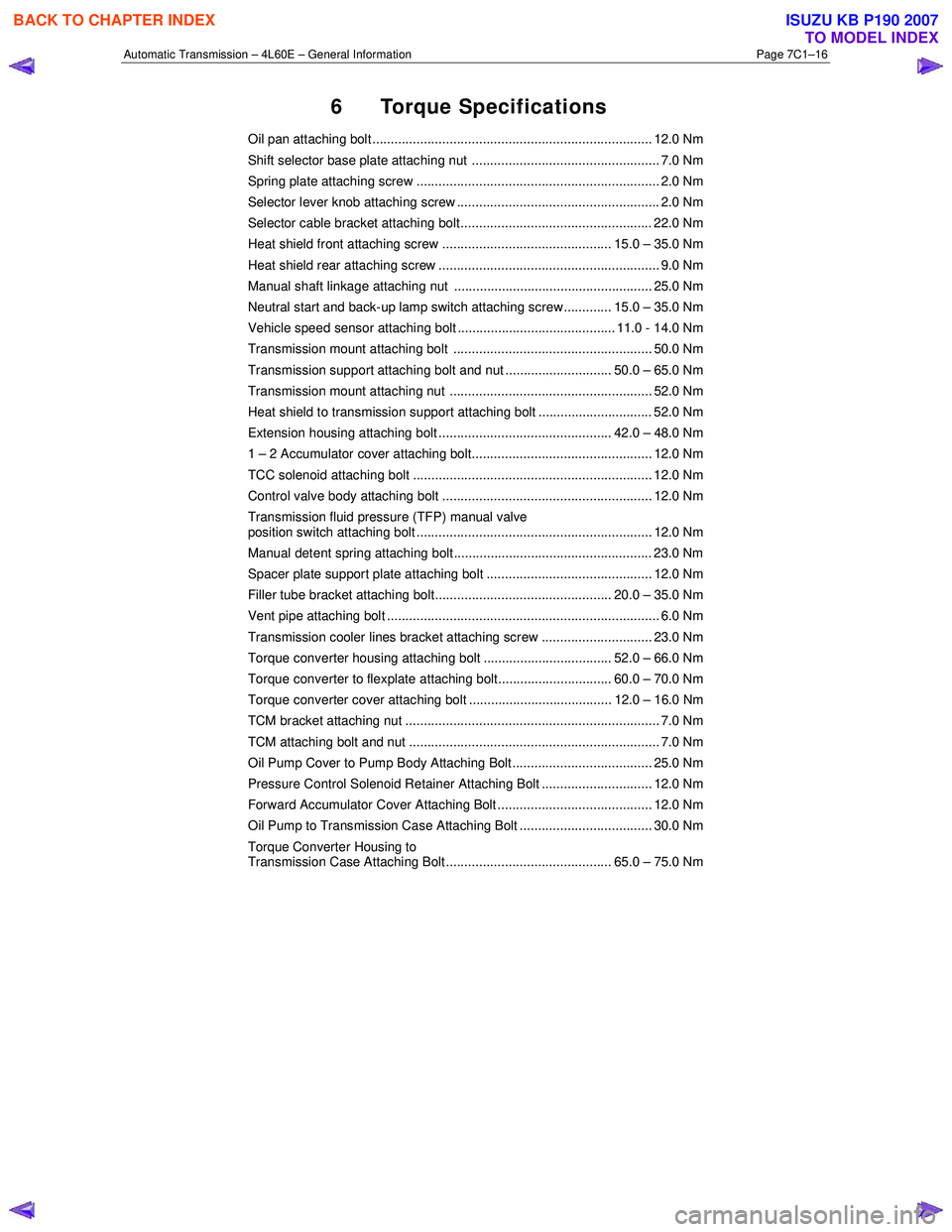
6 Torque Specifications
Oil pan attaching bolt ............................................................................ 12.0 Nm
Shift selector base plate attaching nut ................................................... 7.0 Nm
Spring plate attaching screw .................................................................. 2.0 Nm
Selector lever knob attaching screw ....................................................... 2.0 Nm
Selector cable bracket attaching bolt.................................................... 22.0 Nm
Heat shield front attaching screw .............................................. 15.0 – 35.0 Nm
Heat shield rear attaching screw ............................................................ 9.0 Nm
Manual shaft linkage attaching nut ...................................................... 25.0 Nm
Neutral start and back-up lamp switch attaching screw............. 15.0 – 35.0 Nm
Vehicle speed sensor attaching bolt ........................................... 11.0 - 14.0 Nm
Transmission mount attaching bolt ...................................................... 50.0 Nm
Transmission support attaching bolt and nut ............................. 50.0 – 65.0 Nm
Transmission mount attaching nut ....................................................... 52.0 Nm
Heat shield to transmission support attaching bolt ............................... 52.0 Nm
Extension housing attaching bolt ............................................... 42.0 – 48.0 Nm
1 – 2 Accumulator cover attaching bolt................................................. 12.0 Nm
TCC solenoid attaching bolt ................................................................. 12.0 Nm
Control valve body attaching bolt ......................................................... 12.0 Nm
Transmission fluid pressure (TFP) manual valve
position switch attaching bolt ................................................................ 12.0 Nm
Manual detent spring attaching bolt ...................................................... 23.0 Nm
Spacer plate support plate attaching bolt ............................................. 12.0 Nm
Filler tube bracket attaching bolt................................................ 20.0 – 35.0 Nm
Vent pipe attaching bolt .......................................................................... 6.0 Nm
Transmission cooler lines bracket attaching screw .............................. 23.0 Nm
Torque converter housing attaching bolt ................................... 52.0 – 66.0 Nm
Torque converter to flexplate attaching bolt............................... 60.0 – 70.0 Nm
Torque converter cover attaching bolt ....................................... 12.0 – 16.0 Nm
TCM bracket attaching nut ..................................................................... 7.0 Nm
TCM attaching bolt and nut .................................................................... 7.0 Nm
Oil Pump Cover to Pump Body Attaching Bolt...................................... 25.0 Nm
Pressure Control Solenoid Retainer Attaching Bolt .............................. 12.0 Nm
Forward Accumulator Cover Attaching Bolt .......................................... 12.0 Nm
Oil Pump to Transmission Case Attaching Bolt .................................... 30.0 Nm
Torque Converter Housing to
Transmission Case Attaching Bolt............................................. 65.0 – 75.0 Nm
BACK TO CHAPTER INDEX
TO MODEL INDEX
ISUZU KB P190 2007
Page 3780 of 6020
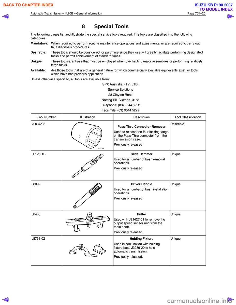
Automatic Transmission – 4L60E – General Information Page 7C1–20
8 Special Tools
The following pages list and illustrate the special service tools required. The tools are classified into the following
categories:
Mandatory:
W hen required to perform routine maintenance operations and adjustments, or are required to carry out
fault diagnosis procedures.
Desirable:
These tools should be considered for purchase since their use will greatly facilitate performing designated
tasks and permit achievement of standard times.
Unique: These tools are those that must be employed when overhauling major assemblies or performing relatively
large tasks.
Available: Are those tools that are of a general nature for which commercially available equivalents exist, or tools
which have had previous application.
Unless otherwise specified, all tools are available from:
SPX Australia PTY. LTD. Service Solutions 28 Clayton Road
Notting Hill, Victoria, 3168
Telephone: (03) 9544 6222
Facsimile: (03) 9544 5222
Tool Number Illustration Description Tool Classification
700-4208
Pass-Thru Connector Remover
Used to release the four locking tangs
on the Pass-Thru connector from the
transmission case.
Previously released Desirable
J6125-1B
Slide Hammer
Used for a number of bush removal
operations.
Previously released Unique
J8092
Driver Handle
Used for a number of bush installation
operations.
Previously released Unique
J8433 Puller
Used with J21427-01 to remove the
output speed sensor ring from the
main shaft.
Previously released Unique
J8763-02 Holding Fixture
Used in conjunction with holding
fixture base J3289-20 to hold
automatic transmission.
Previously released. Unique
BACK TO CHAPTER INDEX
TO MODEL INDEX
ISUZU KB P190 2007
Page 3781 of 6020
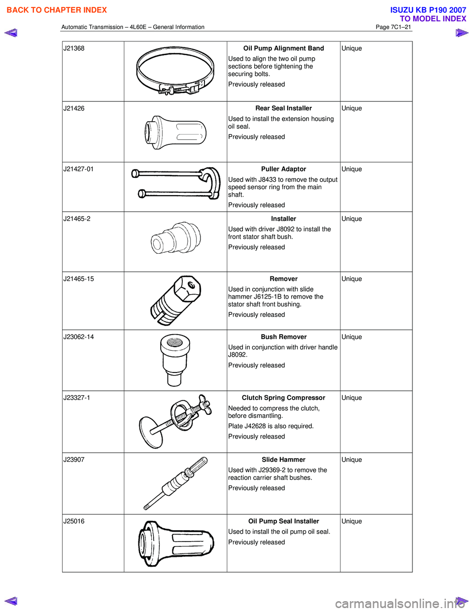
Automatic Transmission – 4L60E – General Information Page 7C1–21
J21368
Oil Pump Alignment Band
Used to align the two oil pump
sections before tightening the
securing bolts.
Previously released Unique
J21426
Rear Seal Installer
Used to install the extension housing
oil seal.
Previously released Unique
J21427-01 Puller Adaptor
Used with J8433 to remove the output
speed sensor ring from the main
shaft.
Previously released Unique
J21465-2
Installer
Used with driver J8092 to install the
front stator shaft bush.
Previously released Unique
J21465-15
Remover
Used in conjunction with slide
hammer J6125-1B to remove the
stator shaft front bushing.
Previously released Unique
J23062-14
Bush Remover
Used in conjunction with driver handle
J8092.
Previously released Unique
J23327-1
Clutch Spring Compressor
Needed to compress the clutch,
before dismantling.
Plate J42628 is also required.
Previously released Unique
J23907
Slide Hammer
Used with J29369-2 to remove the
reaction carrier shaft bushes.
Previously released Unique
J25016
Oil Pump Seal Installer
Used to install the oil pump oil seal.
Previously released Unique
BACK TO CHAPTER INDEX
TO MODEL INDEX
ISUZU KB P190 2007