ECU ISUZU TROOPER 1995 Workshop Manual
[x] Cancel search | Manufacturer: ISUZU, Model Year: 1995, Model line: TROOPER, Model: ISUZU TROOPER 1995Pages: 1928
Page 1736 of 1928
'
9J-112 Supplemental Restraint System
HISTORY DTC 84
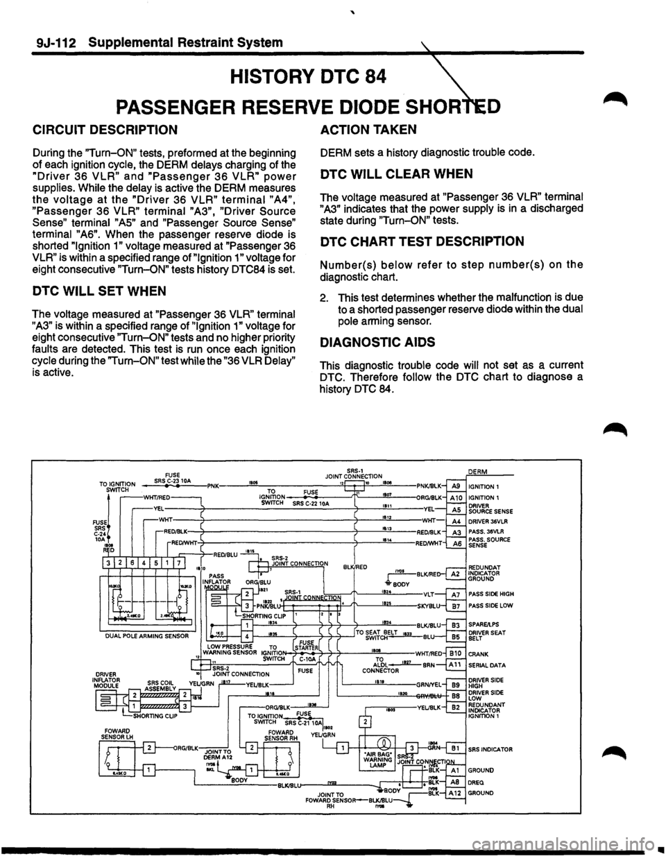
PASSENGER RESERVE DIODE SHOR D
CIRCUIT DESCRIPTION
During the "Turn-ON" tests, preformed at the beginning
of each ignition cycle, the DERM delays charging of the
"Driver 36 VLR" and "Passenger 36 VLR" power
supplies. While the delay is active the DERM measures
the voltage at the "Driver 36 VLR" terminal "A4",
"Passenger 36 VLR" terminal "A3", "Driver Source
Sense"
terminal "AS" and "Passenger Source Sense"
terminal "A6". When the passenger reserve diode is
shorted
"Ignition 1" voltage measured at "Passenger 36
VLR" is within a specified range of "Ignition 1" voltage for
eight consecutive
"Turn-ON" tests history DTC84 is set.
DTC WILL SET WHEN
The voltage measured at "Passenger 36 VLR" terminal
"A3" is within a specified range of "Ignition 1" voltage for
eight consecutive
"Turn-ON" tests and no higher priority
faults are detected. This test
is run once each ignition
cycle during the
"Turn-ON" test while the "36 VLR Delay"
is active.
ACTION TAKEN
DERM sets a history diagnostic trouble code.
DTC WILL CLEAR WHEN
The voltage measured at "Passenger 36 VLR" terminal
"A3" indicates that the power supply is in a discharged
state during
"Turn-ON" tests.
DTC CHART TEST DESCRIPTION
Number(s) below refer to step number(s) on the
diagnostic chart.
2. This test determines whether the malfunction is due
to a shorted passenger reserve diode within the dual
pole arming sensor.
DIAGNOSTIC AIDS
This diagnostic trouble code will not set as a current
DTC. Therefore follow the DTC chart to diagnose a
history
DTC 84.
SRS-1 JOINT CONNECTION
IGNITION 1
IGNITION 1 DRIVER SOURCE SENSE DRIVER 36VLR
PASS. 35VLR
PASS. SOURCE
SENSE
PASS SIDE HIGH
PASS
SIDE LOW
f--'""'-----7---3-7-7-~--1!!!i!03!..4 --BLKIBLU SPARE/I.PS
1---""''----4------4-4-4--_JTO ~~:::~ELT 1133 BLU
1101
Al?,L 1127 CONNECTOR
1811
1120
SRS INDICATOR
..
Page 1781 of 1928
BODY 1Q-23
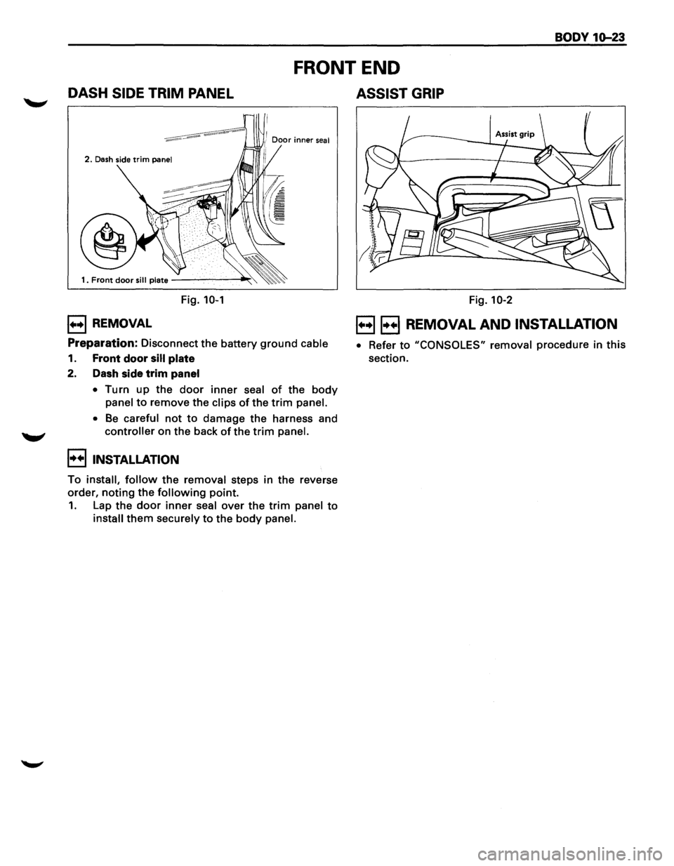
DASH SIDE TRIM PANEL
FRONT END
ASSIST GRIP
2. Dash side trim panel
Fig. 10-1
1++1 REMOVAL
Preparation: Disconnect the battery ground cable
1. Front door sill plate
2. Dash side trim panel
• Turn up the door inner seal of the body
panel to remove the clips of the trim panel.
•
Be careful not to damage the harness and
controller on the back of the trim panel.
I••! INSTALLATION
To install, follow the removal steps in the reverse
order,
noting the following point.
1. Lap the door inner seal over the trim panel to
install them securely to the body panel.
Fig. 10-2
B 8 REMOVAL AND INSTALLATION
• Refer to "CONSOLES" removal procedure in this
section.
Page 1795 of 1928
I••! INSTALLATION
To install, follow the removal steps in the reverse
order,
noting the following point.
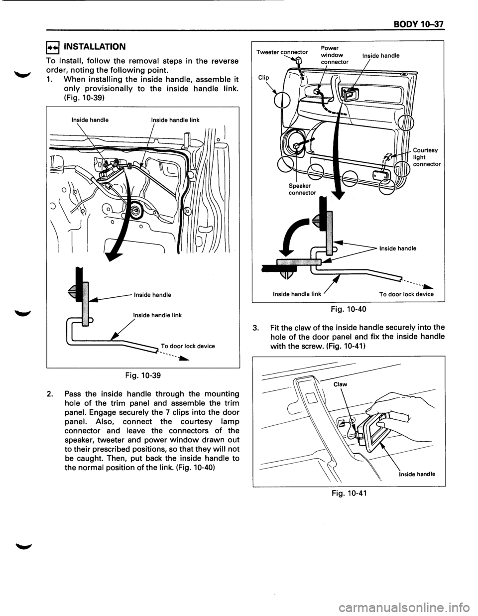
1. When installing the inside handle, assemble it
only provisionally to the inside handle link.
(Fig. 10-39)
Inside handle
Inside handle link
To door lock device ·-. ·--~
Fig. 10-39
2. Pass the inside handle through the mounting
hole of the trim panel and assemble the trim
panel. Engage securely the 7 clips into the door
panel. Also, connect the courtesy lamp
connector and leave the connectors of the
speaker, tweeter and power
window drawn out
to their prescribed positions, so that they will not
be caught. Then, put back the inside handle to
the
normal position of the link. (Fig. 10-40)
Tweeter connector
Speaker connector Power
window connector
Inside
handle link
Fig. 10-40
BODY 10-37
Inside handle
·-. --~
To door lock device
3. Fit the claw of the inside handle securely into the
hole of the door panel and fix the inside handle
with the screw. (Fig. 10-41)
Inside handle
Fig. 10-41
Page 1797 of 1928
3. Door trim panel
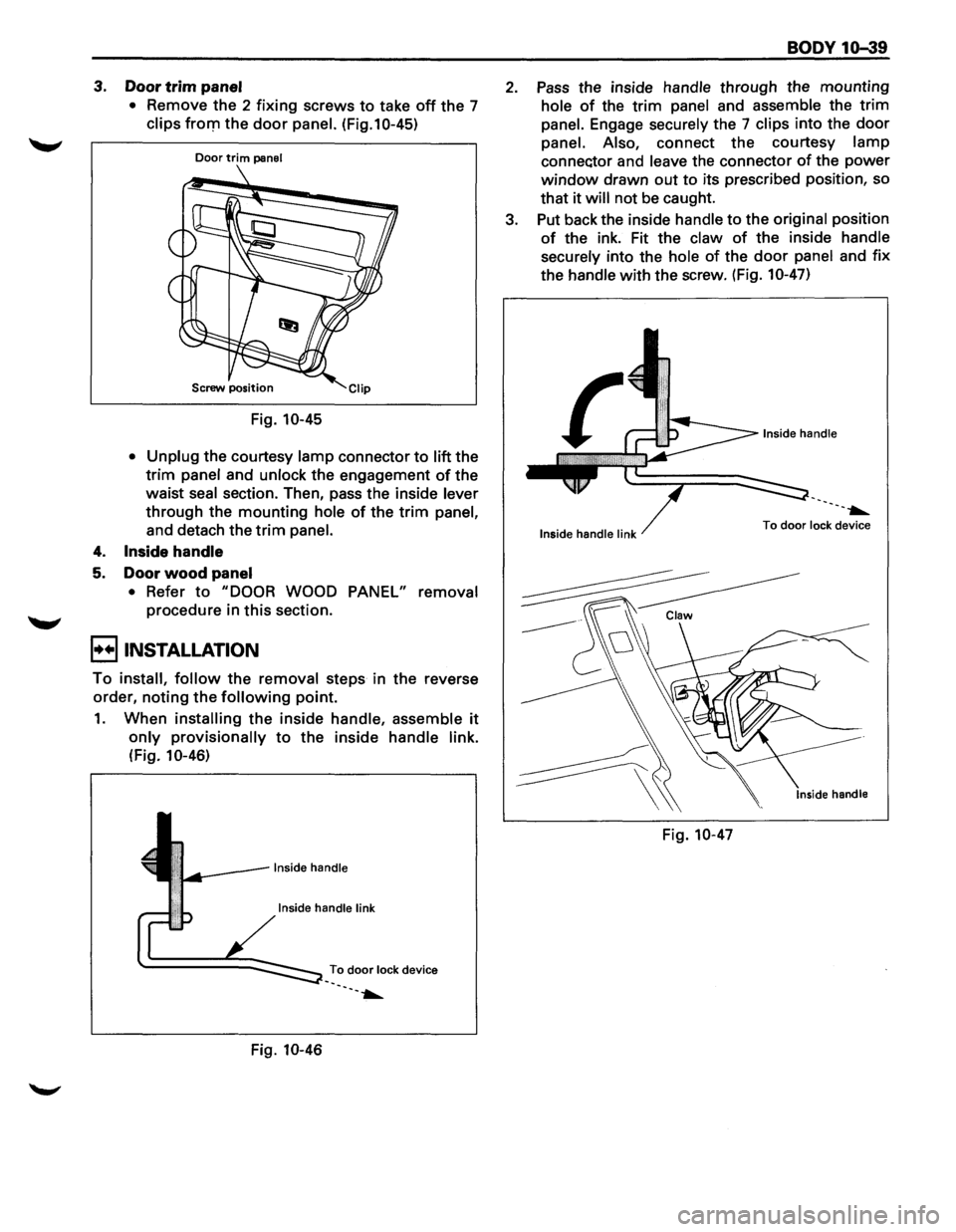
• Remove the 2 fixing screws to take off the 7
clips fro111 the door panel. (Fig.10-45)
Door trim panel
Screw position
Fig. 10-45
• Unplug
the courtesy lamp connector to lift the
trim panel and unlock the engagement of the
waist
seal section. Then, pass the inside lever
through the mounting hole of the trim panel,
and detach the trim panel.
4. Inside handle
5. Door wood panel
• Refer to "DOOR WOOD PANEL" removal
procedure in this section.
B INSTALLATION
To install, follow the removal steps in the reverse
order,
noting the following point.
1. When installing the inside handle, assemble it
only provisionally to the inside handle link.
(Fig. 10-46)
Inside handle link
To door lock device
--.....
Fig. 10-46
BODY 10-39
2. Pass the inside handle through the mounting
hole of the trim panel and assemble the trim
panel. Engage securely the 7 clips into the door
panel. Also, connect the courtesy lamp
connec:tor and leave the connector of the power
window drawn out to its prescribed position, so
that
it will not be caught.
3. Put back the inside
handle to the original position
of the ink. Fit the claw of the inside handle
securely
into the hole of the door panel and fix
the handle with the screw. (Fig. 10-47)
---.....
Inside handle link To door lock
device
Fig. 10-47
Page 1823 of 1928
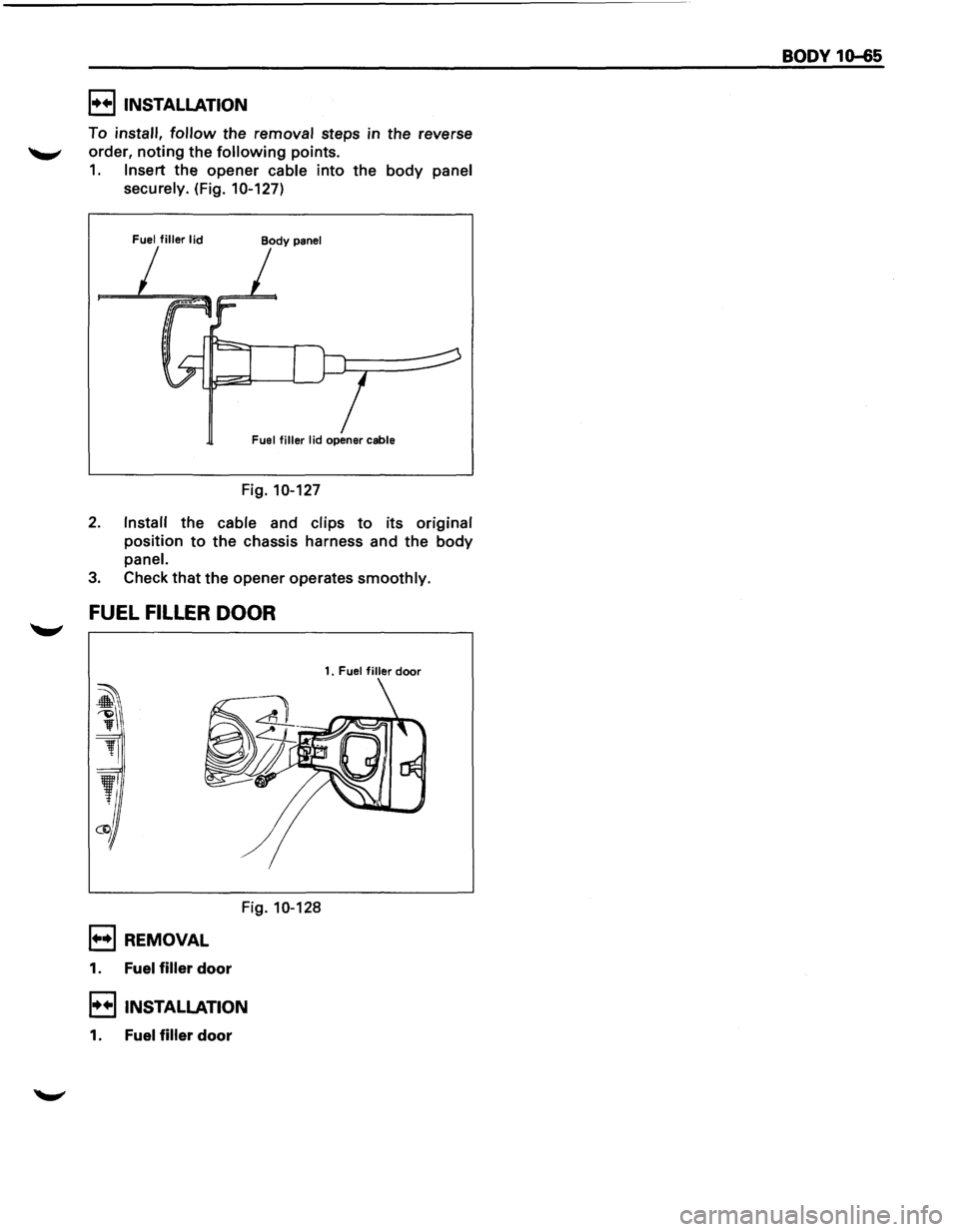
I•+IINSTALLATION
To install, follow the removal steps in the reverse
'-""' order, noting the following points.
1. Insert the opener cable into the body panel
securely.
(Fig. 10-127)
Fuel filler lid Body panel
Fuel filler lid opener cable
Fig. 10-127
2. Install the cable and clips to its original
position to the chassis harness and the body
panel.
3. Check that the opener operates smoothly.
FUEL FILLER DOOR
Fig. 10-128
1++1 REMOVAL
1. Fuel filler door
I•+IINSTALLATION
1. Fuel filler door
1. Fuel filler door
BODY 10-65
Page 1828 of 1928
10-70 BODY
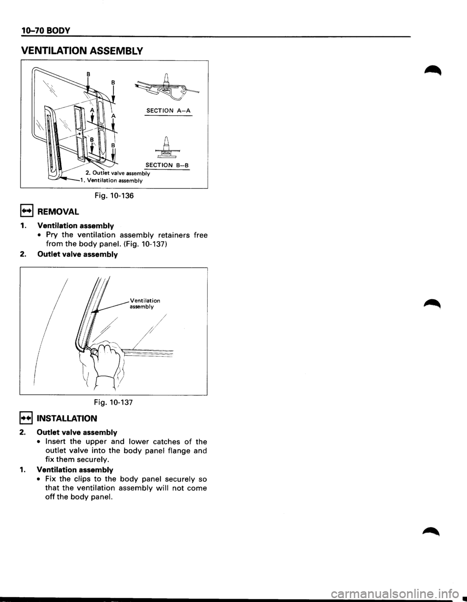
VENTILATION ASSEMBLY
SECTION A-A
SECTION B-B
2. Outlet valve assembly 1. Ventilation assembly
Fig. 10-136
1+•1 REMOVAL
1. Ventilation assembly
• Pry the ventilation assembly retainers free
from the body panel. (Fig. 10-137)
2. Outlet valve assembly
Ventilation assembly
/
/
Fig. 10-137
I•+IINSTALLATION
2. Outlet valve assembly
• Insert the upper and lower catches of the
outlet valve into the body panel flange and
fix them securely.
1. Ventilation assembly
• Fix the clips to the body panel securely so
that the ventilation assembly will not come
off the body panel.
•
Page 1834 of 1928
10-76 BODY
1+•1 REMOVAL
Preparation: Disconnect the battery ground cable
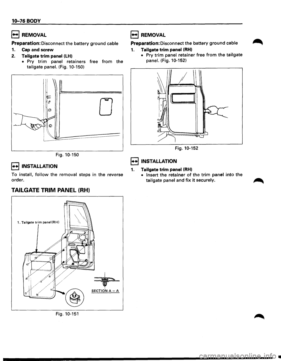
1. Cap and screw
2. Tailgate trim panel (LH)
• Pry trim panel retainers free from the
tailgate panel. (Fig. 1 0-150)
Fig. 10-150
!••I INSTALLATION
0
To install, follow the removal steps in the reverse
order.
TAILGATE TRIM PANEL (RH)
1. Tailgate trim panei(RH)
+ @ SECTIONA-A
Fig. 10-151
1++1 REMOVAL
Preparation: Disconnect the battery ground cable
1. Tailgate trim panel (RH)
• Pry trim panel retainer free from the tailgate
panel.
(Fig. 10-152)
Fig. 10-152
!••I INSTALLATION
1. Tailgate trim panel (RH)
• Insert the retainer of the trim panel into the
tailgate panel and fix it securely.
•
Page 1841 of 1928
l••liNSTALLATION
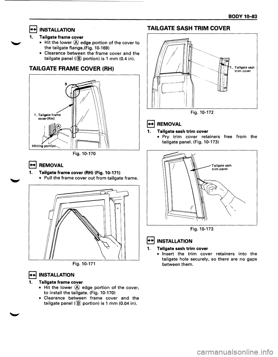
1. Tailgate frame cover
"-"' • Hit the lower @ edge portion of the cover to
the tailgate flange.( Fig. 1 0-169)
• Clearance
between the frame cover and the
tailgate panel (@ portion) is 1 mm (0.4 in).
TAILGATE FRAME COVER (RH)
Fig. 10-170
l••l REMOVAL
1. Tailgate frame cover (RH) (Fig.10-171)
• Pull the frame cover out from tailgate frame.
Fig.
10-171
I••! INSTALLATION
1. Tailgate frame cover
• Hit the lower @ edge portion of the cover,
to install the tailgate. (Fig. 10-170)
• Clearance
between frame cover and the
tailgate panel (@ portion) is 1 mm (0.04 in).
BODY 10-83
TAILGATE SASH TRIM COVER
Fig. 10-172
l••l REMOVAL
1. Tailgate sash trim cover
1 . Tailgate sash trim cover
• Pry trim cover retainers free from the
tailgate panel. (Fig. 10-173)
Tai I gate sash trim panel
Fig. 10-173
I••! INSTALLATION
1. Tailgate sash trim cover
• Insert the trim cover retainers into the
tailgate hole securely, so there are no gaps
between
them.
Page 1842 of 1928
1o-84 BODY
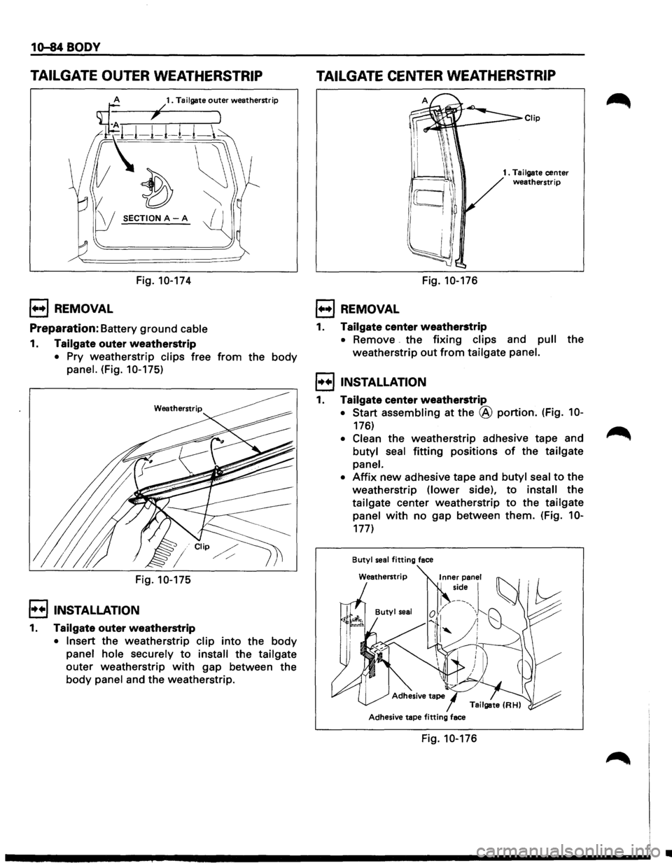
TAILGATE OUTER WEATHERSTRIP
SECTION A-A
Fig. 10-174
l••l REMOVAL
Preparation: Battery ground cable
1. Tailgate outer weatherstrip
• Pry weatherstrip clips free from the body
panel. (Fig. 10-175)
Fig. 10-175
l••IINSTALLATION
1. Tailgate outer weatherstrip
• Insert the weatherstrip clip into the body
panel hole securely to install the tailgate
outer weatherstrip with gap between the
body panel and the weatherstrip.
TAILGATE CENTER WEATHERSTRIP
Fig. 10-176
1••1 REMOVAL
1. Tailgate center weatherstrip
1 . Tailgate center weatherstrip
• Remove the fixing clips and pull the
weatherstrip
out from tailgate panel.
l•+IINSTALLATION
1. Tailgate center weatherstrip
• Start assembling at the @ portion. (Fig. 10-
176)
• Clean the weatherstrip adhesive tape and
butyl seal
fitting positions of the tailgate
panel.
•
Affix new adhesive tape and butyl seal to the
weatherstrip
(lower side), to install the
tailgate center weatherstrip
to the tailgate
panel
with no gap between them. (Fig. 10-
177)
Butyl seal fitting face
Adhesive
tape/ Tailgate (RH)
Adhesive
tape fitting face
Fig. 10-176
•
Page 1856 of 1928
10-98 BODY
6. Connecting shaft
7. Seat back assembly
7a. Band hook cover
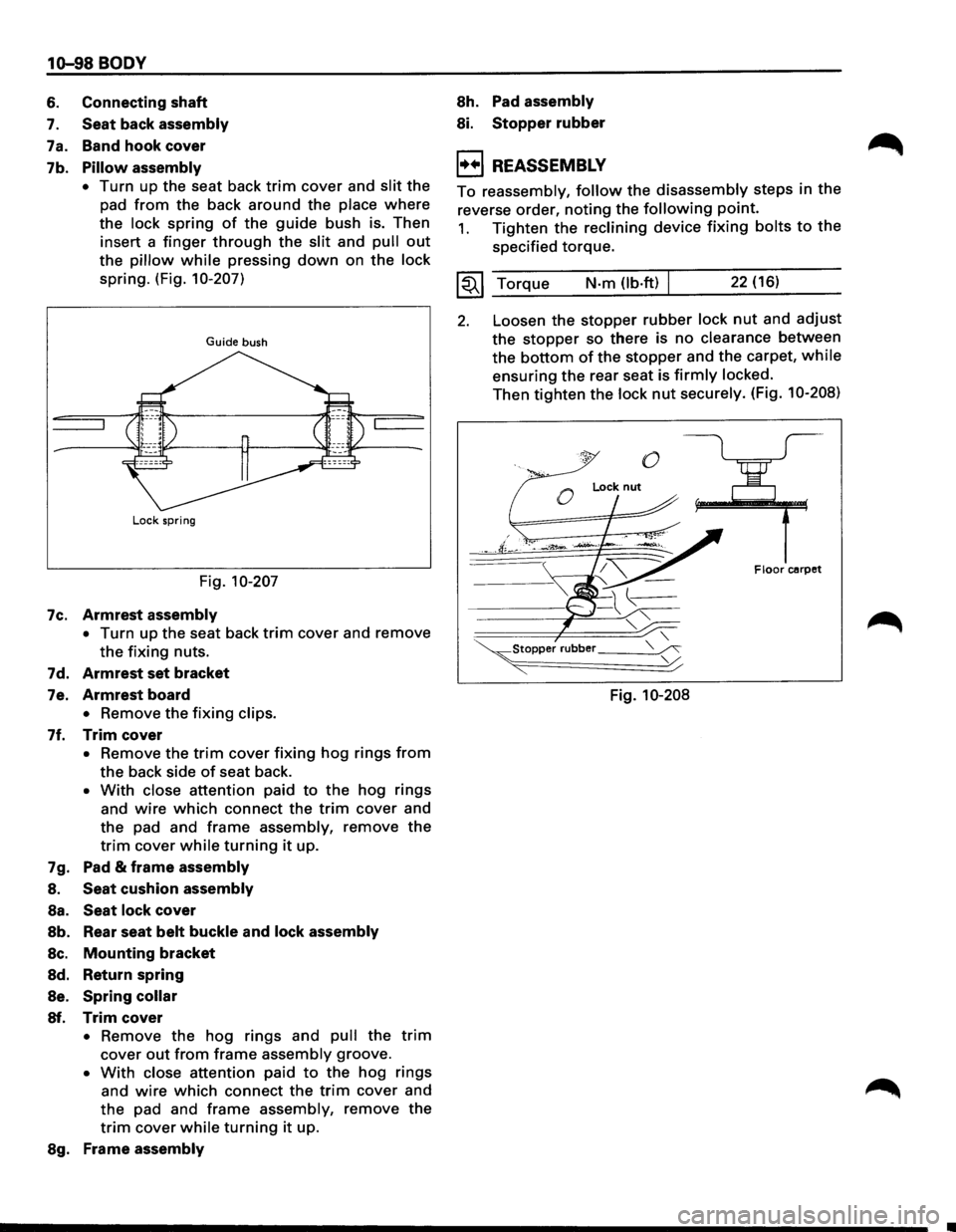
7b.
Pillow assembly
•
Turn up the seat back trim cover and slit the
pad
from the back around the place where
the lock spring of the guide bush is. Then
insert a
finger through the slit and pull out
the pillow while pressing down on the lock
spring. (Fig. 10-207)
Guide bush
Lock spring
Fig. 10-207
7c.
Armrest assembly
• Turn up the seat back trim cover and remove
the fixing nuts.
7d.
Armrest set bracket
7e. Armrest board
• Remove the fixing clips.
7f. Trim cover
• Remove the trim cover fixing hog rings from
the back side of seat back.
• With close attention paid to the hog rings
and
wire which connect the trim cover and
the pad and
frame assembly, remove the
trim cover while turning it up.
7g. Pad
& frame assembly
8. Seat cushion assembly
Sa. Seat lock cover
Sb. Rear seat belt buckle and lock assembly
Sc. Mounting bracket
Sd. Return spring
Se. Spring collar
Sf. Trim cover
• Remove the hog rings and pull the trim
cover out from frame assembly groove.
• With close attention paid to the hog rings
and
wire which connect the trim cover and
the pad and frame assembly, remove the
trim cover while turning it up.
Sg. Frame assembly
Sh. Pad assembly
Si. Stopper rubber
1++1 REASSEMBLY
To reassembly, follow the disassembly steps in the
reverse order, noting the following point.
1. Tighten the reclining device fixing bolts to the
specified torque.
~~~ Torque N-m (lb.ft) 22 (16)
2. Loosen the stopper rubber lock nut and adjust
the stopper so there is no clearance between
the bottom of the stopper and the carpet, while
ensuring the rear seat is firmly locked.
Then tighten the lock nut securely. (Fig. 10-208)
0
0
Lock nut
F Iocr carpet
Fig. 10-208