ISUZU TROOPER 1995 Workshop Manual
Manufacturer: ISUZU, Model Year: 1995, Model line: TROOPER, Model: ISUZU TROOPER 1995Pages: 1928
Page 1151 of 1928
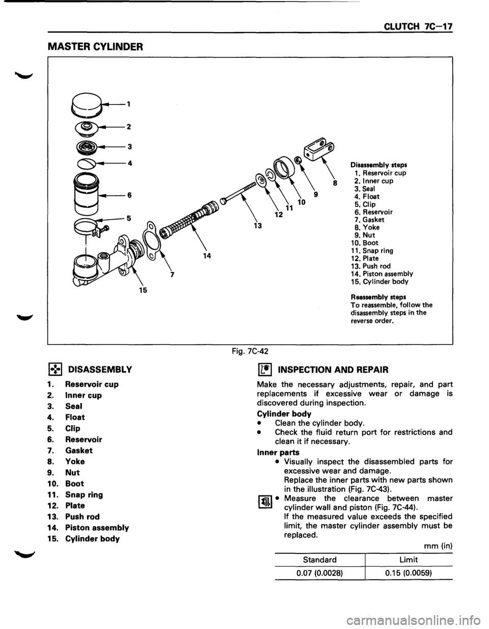
MASTER CYLINDER
l•!•l DISASSEMBLY
1. Reservoir cup
2. Inner cup
3. Seal
4. Float
5. Clip
6. Reservoir
7. Gasket
8. Yoke
9. Nut
10. Boot
11. Snap ring
12. Plate
13. Push rod
14. Piston assembly
15. Cylinder body
..........
Fig. 7C-42
CLUTCH 7C-17
Disassembly steps
1. Reservoir cup
2. Inner cup
3. Seal 4. Float 5. Clip 6. Reservoir 7. Gasket 8. Yoke 9. Nut 10. Boot
11. Snap ring
12. Plate
13. Push rod
14. Piston assembly
15. Cylinder
body
Reassembly steps To reassemble, follow the disassembly steps in the
reverse order.
IL•I INSPECTION AND REPAIR
Make the necessary adjustments, repair, and part
replacements
if excessive wear or damage is
discovered during inspection.
Cylinder body
• Clean the cylinder body.
• Check the fluid return port for restrictions and
clean
it if necessary.
Inner parts
• Visually inspect the disassembled parts for
excessive wear and damage.
Replace the inner parts
with new parts shown
in the
illustration (Fig. 7C-43).
ltil• Measure the clearance between master
cylinder
wall and piston (Fig. 7C-44).
If the measured value exceeds the specified
limit, the master cylinder assembly
must be
replaced.
mm (in)
Standard Limit
0.07
(0.0028) 0.15 (0.0059)
Page 1152 of 1928

7C-18 CLUTCH
Fig. 7C-43
Fig. 7C-44
SLAVE CYLINDER
~\
4
5
3
l•!•l REASSEMBLY
To reassemble, follow the disassembly steps in the
reverse
order, noting the following points:
1. Cylinder body
D • lmmHrse the cylinder body in clean brake fluid
L:::J (Fig. 7C-45).
2. Piston assembly
D Before installing, apply a thin coat of rubber
L:::J grease to the piston. Install cup in groove in
IE41 piston with the lip turned to front of cylinder.
Use care to prevent damaging the lip of the piston
seat.
Fig.
7C-45
Disassembly steps
1. Boot
2. Push rod
3. Piston and piston
cup 4. Spring
5. Cylinder body
Reassembly steps
To reassemble, follow the disassembly steps in the reverse order.
Fig. 7C-46
•
Page 1153 of 1928
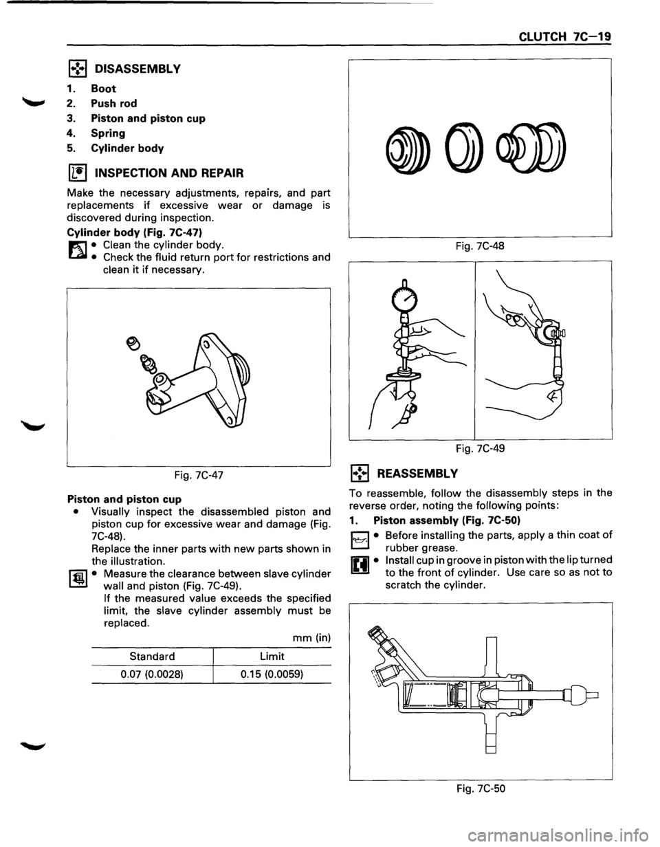
l.-!•1 DISASSEMBLY
1. Boot
2. Push rod
3. Piston and piston cup
4.
Spring
5. Cylinder body
IL•I INSPECTION AND REPAIR
Make the necessary adjustments, repairs, and part
replacements
if excessive wear or damage is
discovered during inspection.
Cylinder body (Fig. 7C-47)
E'1 • Clean the cylinder body.
Lal • Check the fluid return port for restrictions and
clean it if necessary.
Fig. 7C-47
Piston and piston cup
• Visually inspect the disassembled piston and
piston cup
for excessive wear and damage (Fig.
7C-48).
Replace the inner parts
with new parts shown in
the
illustration.
l'fil • Measure the clearance between slave cylinder
l.!!!l wall and piston (Fig. 7C-49).
If the measured value exceeds the specified
limit, the slave cylinder assembly
must be
replaced.
mm (in)
Standard Limit
0.07 (0.0028) 0.15 (0.0059)
Fig. 7C-48
Fig. 7C-49
l•!.-1 REASSEMBLY CLUTCH
7C-19
To
reassemble, follow the disassembly steps in the
reverse order, noting the
following points:
1. Piston assembly (Fig. 7C-50)
D • Before installing the parts, apply a thin coat of
L::::.l rubber grease.
0 • Install cup in groove in piston with the lip turned
U to the front of cylinder. Use care so as not to
scratch the cylinder.
Fig.
7C-50
Page 1154 of 1928
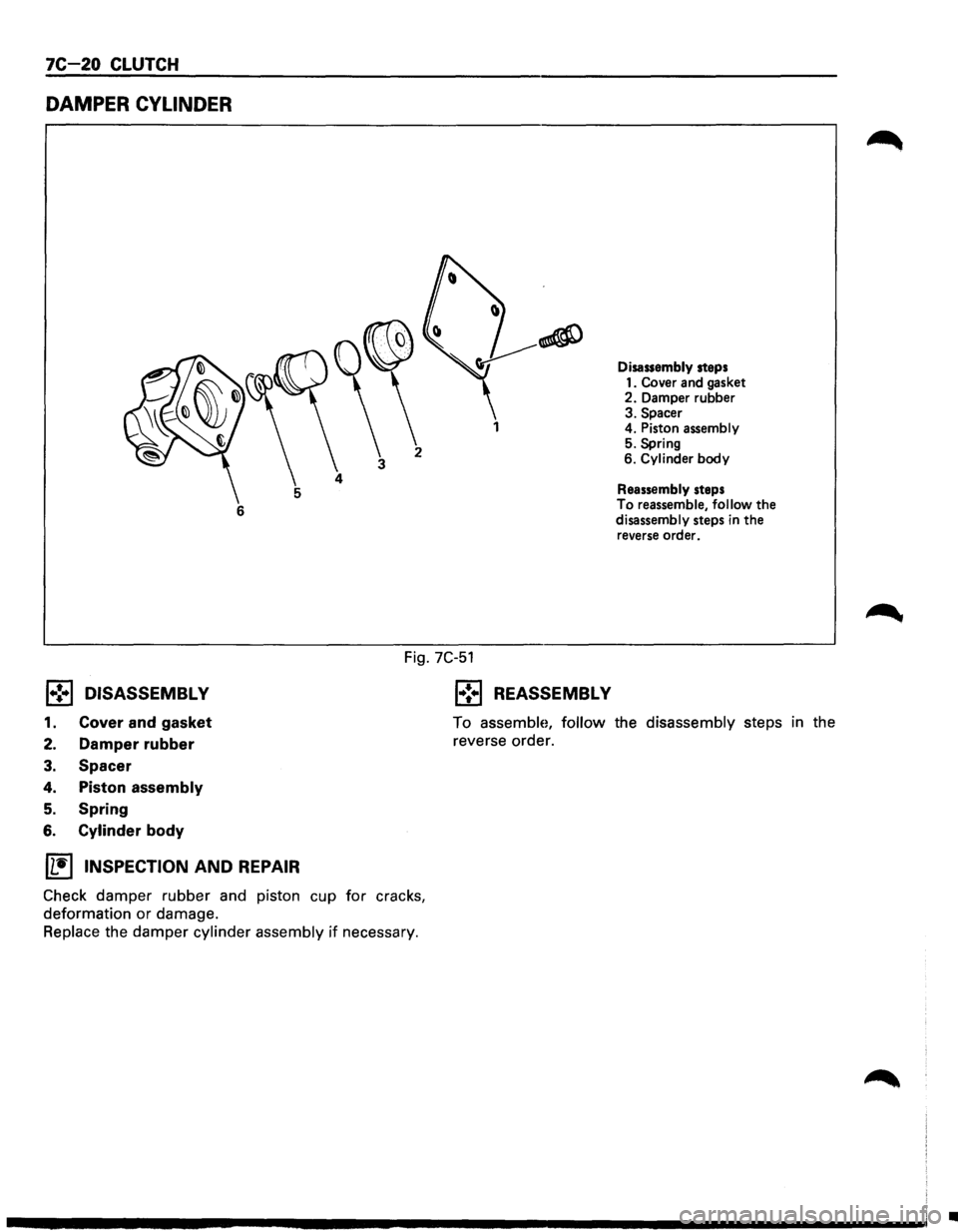
7C-20 CLUTCH
DAMPER CYLINDER
6
(®)
2 1
Disassembly steps
1. Cover and gasket
2. Damper rubber
3. Spacer 4. Piston assembly 5. Spring
6. Cylinder body
Reassembly steps To reassemble, follow the disassembly steps in the
reverse order.
Fig. 7C-51
l .. !•l DISASSEMBL V
1. Cover and gasket
2. Damper rubber
3. Spacer
4. Piston
assembly
5. Spring
6. Cylinder body
IL•I INSPECTION AND REPAIR
Check damper rubber and piston cup for cracks,
deformation
or damage.
Replace the damper cylinder assembly if necessary.
1•! .. 1 REASSEMBL V
To assemblo, follow the disassembly steps in the
reverse order.
•
Page 1155 of 1928
CLUTCH 7C-21
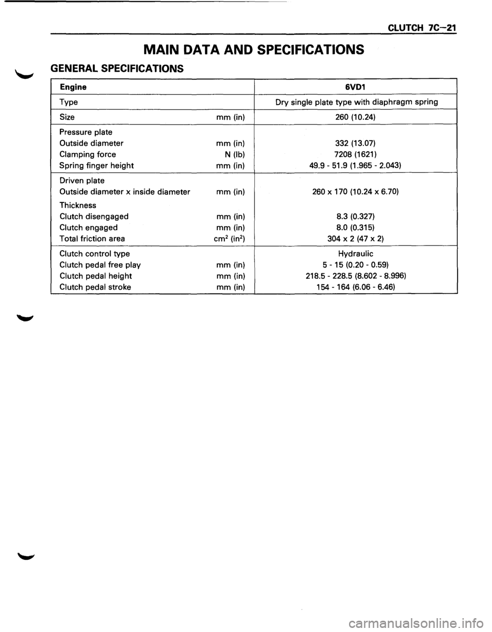
MAIN DATA AND SPECIFICATIONS
GENERAL SPECIFICATIONS
Engine 6VD1
Type Dry single plate type with diaphragm spring
Size mm (in) 260 (10.24)
Pressure plate
Outside
diameter mm (in) 332 (13.07)
Clamping force N (lb) 7208 (1621)
Spring finger height mm (in) 49.9 -51.9 (1.965 -2.043)
Driven plate
Outside
diameter x inside diameter mm (in) 260 X 170 (10.24 X 6.70)
Thickness
Clutch disengaged mm (in) 8.3 (0.327)
Clutch engaged mm (in) 8.0 (0.315)
Total friction area cm2 (in2
) 304 X 2 (47 X 2)
Clutch control type Hydraulic
Clutch pedal
free play mm (in) 5 -15 (0.20 -0.59)
Clutch pedal height mm (in) 218.5 -228.5 (8.602 -8.996)
Clutch pedal stroke mm (in) 154 -164 (6.06 -6.46)
Page 1156 of 1928
![ISUZU TROOPER 1995 Workshop Manual 7C-22 CLUTCH
TORQUE SPECIFICATIONS N·m (lb·ft)
76(56)]
Fig. 7C-52
•](/img/61/57183/w960_57183-1155.png "ISUZU TROOPER 1995 Workshop Manual 7C-22 CLUTCH
TORQUE SPECIFICATIONS N·m (lb·ft)
76(56)]
Fig. 7C-52
•")
7C-22 CLUTCH
TORQUE SPECIFICATIONS N·m (lb·ft)
76(56)]
Fig. 7C-52
•
Page 1157 of 1928
CLUTCH 7C-23
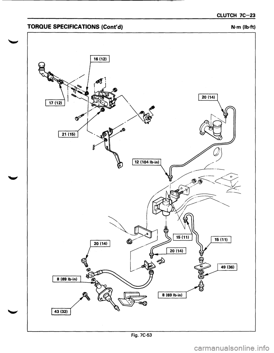
TORQUE SPECIFICATIONS (Cont'd) N·m (lb·ft)
16 (12)
12
(104 lb·in)
8 (691b·in)
8 (691b·in)
Fig. 7C-53
Page 1158 of 1928
7C-24 CLUTCH
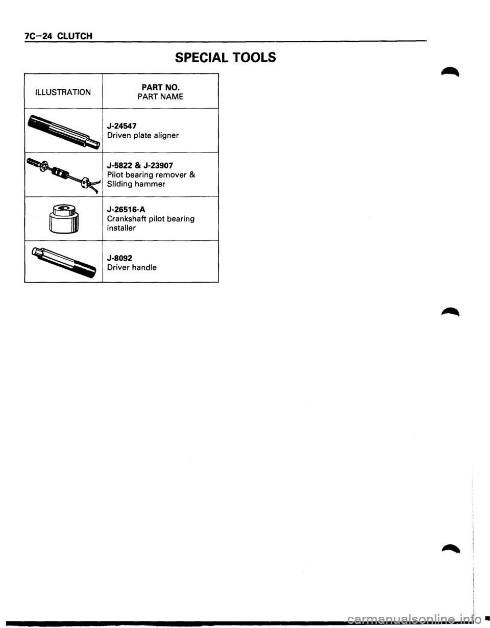
ILLUSTRATION
SPECIAL TOOLS
PART NO.
PART NAME
J-24547 Driven
plate aligner
J-5822 & J-23907
Pilot bearing remover &
Sliding hammer
J-26516-A Crankshaft
pilot bearing
installer
J-8092
Driver handle
•
Page 1159 of 1928
TRANSFER CASE 7D-1
SECTION 70
TRANSFER CASE
w CAUTION:
When fasteners are removed, always reinstall them at the same location from which they were removed. If a
fastener needs
to be replaced, use the correct part number fastener for that application. If the correct part
number is not available, a fastener
of equal size and strength (or stronger) may be used. Fasteners that are
not reused, and those requiring thread locking compound, will
be called out. The correct torque values must
be used when installing fasteners that require torque.
If the above conditions are not followed, parts or
system damage could result.
CONTENTS
General Description ................... 7D-1
Construction . . . . . . . . . . . . . . . . . . . . . . . . . 7D-2
On-Vehicle Service .................... 7D-3
Transfer
Case (A/T) .................. 7D-3
Transfer Rear
Oil Seal ................ 7D-5
Unit Repair ........................... 7D-8
Transfer
Case Assembly (AfT) ........ 7D-8
Transfer Rear
Case Assembly . .
. . . . . 7D-11
Detent, Shift Arm, And
Interlock Pin (Transfer
Case Assembly) . .
. . . . . . . . . . . . . . . . . . 7D-14 Transfer
Case
Assembly . .
. . . . . . . . . .
7D-17
Main Data And Specifications . . . . . . . .
70-29
General
Specifications . .
. . . . . . . . . . . .
70-29
Torque
Specifications ............... 7D-30
Special Tools
........................ 7D-32
GENERAL DESCRIPTION
The transfer case is used to provide a means of
providing power flow to the front axle. The transfer
case also provides a means of disconnecting the front
axle, providing better fuel economy and quieter
operation when the vehicle is driven
on improved
roads where four wheel drive is not required.
In
addition, the transfer case provides an additional gear
reduction when placed in low range, which
is useful
when difficult off-road conditions are encountered. A
floor mounted shift lever is used to select the
operating range. When four wheel drive has been
selected, the four wheel drive indicator light is
designed to come
on when the front axle has been
engaged.
Page 1160 of 1928
70-2 TRANSFER CASE
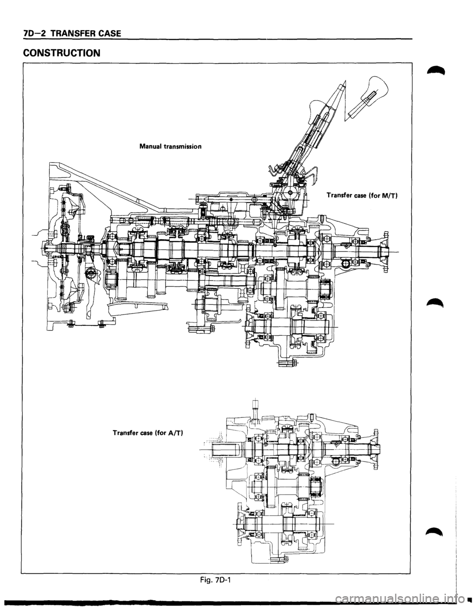
CONSTRUCTION
Manual transmission Transfer case (for M/T)
Transfer case (for A/T)
Fig. 70-1
..