air condition ISUZU TROOPER 1995 Owners Manual
[x] Cancel search | Manufacturer: ISUZU, Model Year: 1995, Model line: TROOPER, Model: ISUZU TROOPER 1995Pages: 1928
Page 279 of 1928
FRONT DRIVING AXLE 4C-1
SECTION 4C
FRONT DRIVING AXLE
'f CAUTION:
When fasteners are removed, always reinstall them at the same location from which they were removed.
If a fastener needs to be replaced, use the correct part number fastener for that application. If the correct
part
number fastener is not available, a fastener of equal size and strength (or stronger) may be used.
Fasteners
that are not reused, and those requiring thread locking compound, will be called out. The
correct
torque values must be used when installing fasteners that require torque. If the above conditions
are not followed, parts or system damage could result.
CONTENTS
General Description . . . . . . . . . . . . . . . . . . . . 4C-1
Diagnosis
of Front Driving Axle . . . . . . . . . . . 4C-2
Automatic Locking Free Wheel Hub . . . . . 4C-3
On-Vehicle Service ..................... 4C- 4
Pinion
Shaft Oil Seal Replacement . . . . . . 4C-4
Front Drive Shaft Joints Replacement . . . 4C-5
Front Hub Bearing Preload Check . . . . . . . 4C-5
Unit Repair . . . . . . . . . . . . . . . . . . . . . . . . . . . . 4C-6
Front Drive Axle Assembly . . . . . . . . . . . . 4C-6
Front Axle Drive Shaft . . . . . . . . . . . . . . . . 4C-9
Differential Assembly ................. 4C-14
Differential Cage Assembly . . . . . . . . . . . . 4C-24
Front Hub and Disc (4WD Model with
Automatic Locking Hub) . . . . . . . . . . . . 4C-28
Main Data and Specifications . . . . . . . . . . . . 4C-37
General Specifications . .
. . . . . . . . . . . . . . 4C-37
Torque Specifications ................. 4C-38
Special Tools .......................... 4C-41
GENERAL DESCRIPTION
This publication contains essential removal, instal
lation,
adjustment and maintenance procedures.
The
front axle utilizes a central disconnect type front
axle/transfer case system. The
drive axles are completely flexible assemblies,
consisting
of inner and outer constant velocity (CV)
drive shaft joints connected by an axle shaft. For
description
of front propeller shaft and universal
joint, refer to Section 4A "PROPELLER SHAFT".
Page 283 of 1928
2. Flange
3. Oil seal
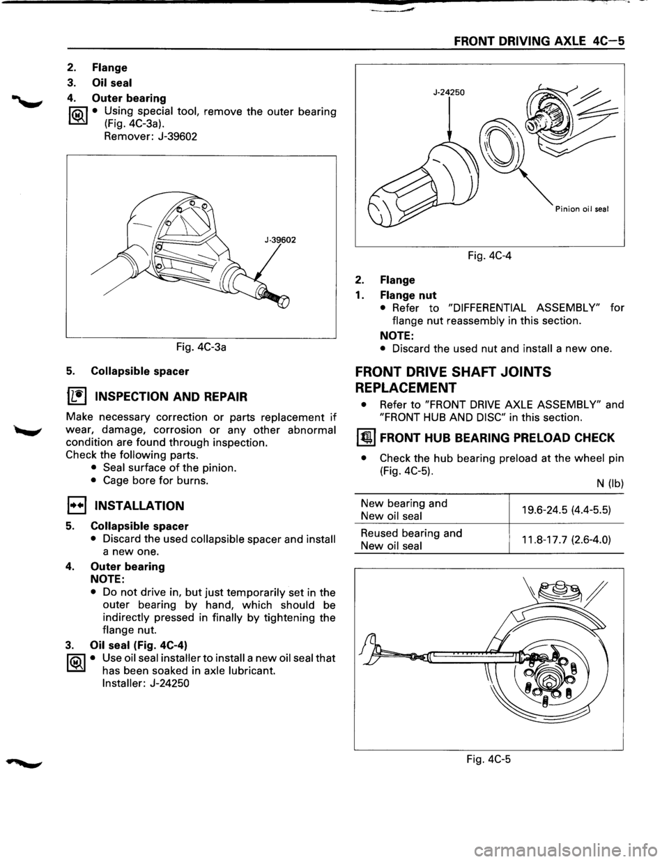
4. Outer bearing
f'Qil • Using special tool, remove the outer bearing
~ (Fig. 4C-3a).
Remover: J-39602
FRONT DRIVING AXLE 4C-5
Fig. 4C-4
2. Flange
1. Flange nut
• Refer to "DIFFERENTIAL ASSEMBLY" for
flange
nut reassembly in this section.
NOTE:
Fig. 4C-3a • Discard the used nut and install a new one.
5. Collapsible spacer
1L:~'I INSPECTION AND REPAIR
Make necessary correction or parts replacement if
wear, damage, corrosion or any other abnormal
condition are found through inspection.
Check the
following parts.
• Seal surface of the pinion.
• Cage bore for burns.
1••1 INSTALLATION
5. Collapsible spacer
• Discard the used collapsible spacer and install
a new one.
4. Outer bearing
NOTE:
• Do not drive in, but just temporarily set in the
outer bearing by hand, which should be
indirectly pressed in
finally by tightening the
flange nut.
3. Oil seal (Fig. 4C-4)
f'Qil • Use oil seal installer to install a new oil seal that
~ has been soaked in axle lubricant.
Installer: J-24250
FRONT DRIVE SHAFT JOINTS
REPLACEMENT
• Refer to "FRONT DRIVE AXLE ASSEMBLY" and
"FRONT HUB AND DISC" in this section.
~ FRONT HUB BEARING PRELOAD CHECK
• Check the hub bearing preload at the wheel pin
(Fig. 4C-5).
New bearing and
New oil seal
Reused bearing and
New
oil seal
Fig.
4C-5
N (lb)
19.6-24.5 (4.4-5.5)
11.8-17.7 (2.6-4.0)
Page 289 of 1928
__,.
9. Ball retainer
10. Ball guide
11. Bellows
12. Band
13. 14.
15.
16.
17.
18.
19.
20.
21.
22.
23.
24. 25.
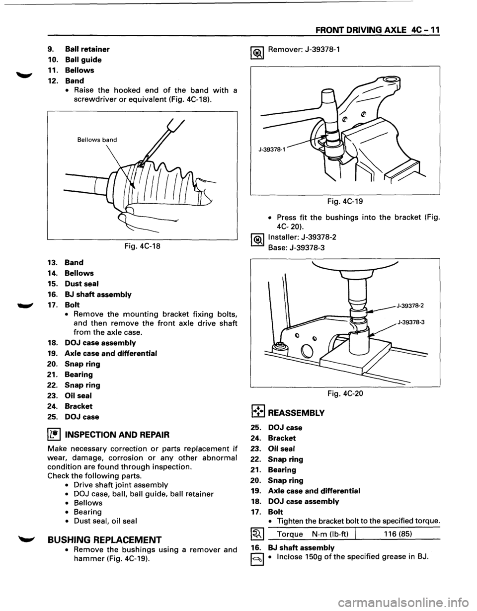
• Raise the hooked end of the band with a
screwdriver or equivalent (Fig. 4C-18).
Bellows band
Fig. 4C-18
Band
Bellows
Dust seal
BJ shaft assembly
Bolt
• Remove the mounting bracket fixing bolts,
and then remove the front axle drive shaft
from the axle case.
DOJ case assembly
Axle case and differential
Snap ring
Bearing
Snap ring
Oil seal
Bracket
DOJ case
I L•IINSPECTION AND REPAIR
Make necessary correction or parts replacement if
wear, damage, corrosion or any other abnormal
condition are found through inspection.
Check
the following parts.
• Drive shaft joint assembly
• DOJ
case, ball, ball guide, ball retainer
• Bellows
• Bearing
• Dust seal, oil seal
~ BUSHING REPLACEMENT
• Remove the bushings using a remover and
hammer (Fig. 4C-19).
FRONT DRIVING AXLE 4C -11
1 (ij),_j Remover: J-39378-1
Fig. 4C-19
• Press fit the bushings into the bracket (Fig.
4C-20).
j(ij),_jlnstaller:
J-39378-2
Base: J-39378-3
Fig.
4C-20
l•!•l REASSEMBLY
25. DOJ case
24. Bracket
23.
Oil seal
22. Snap ring
21.
Bearing
20.
Snap ring
19. Axle case and differential
18. DOJ case assembly
17. Bolt
• Tighten the bracket bolt to the specified torque.
~~~ Torque N-m (lb-ft) I 116 (85)
16. BJ
shaft assembly
1-c:::lcll • Inclose 150g ofthe specified grease in BJ.
Page 303 of 1928
![ISUZU TROOPER 1995 Owners Manual (1!] INSPECTION AND REPAIR
Make necessary correction or parts replacement if
~ wear, damage, corrosion or any other abnormal
condition are found through inspection.
Check the
following part](/img/61/57183/w960_57183-302.png "ISUZU TROOPER 1995 Owners Manual (1!] INSPECTION AND REPAIR
Make necessary correction or parts replacement if
~ wear, damage, corrosion or any other abnormal
condition are found through inspection.
Check the
following part")
(1!] INSPECTION AND REPAIR
Make necessary correction or parts replacement if
~ wear, damage, corrosion or any other abnormal
condition are found through inspection.
Check the
following parts.
• Ring gear, pinion gear
• Bearing
• Side gear, pinion gear, cross pin
• Differential cage, carrier
• Thrust washer
• Oil seal
Ring gear replacement
1) The ring gear should always be replaced with
the drive pinion as a set.
2) Clean the ring gear threaded holes to remove
the
locking agent.
~~~3) When installing the ring gear, apply LOCTITE
271 or equivalent to all the threaded area and
half of the unthreaded area of the bolt.
4) Discard used bolts and install new ones.
I~I __ T_o_rq~u_e __ N_·m~(l_b·_ft~l_IL_ ___ 1_0_8~(8_0_l __ __
5) Tighten the fixing bolts in a diagonal
sequence as illustrated (Fig. 4C-63).
Fig. 4C-63
H'ffil Clearance between the differential pinion and
L!l!l the cross pin measurement (Fig. 4C-64).
mm (in)
Standard Limit
0.06 -0.12 (0.002 -0.005)
0.2 (0.008)
FRONT DRIVING AXLE 4C-25
Fig. 4C-64
rfi:i1 Clearance between the side gear and the
L!l!l differential box (Fig. 4C-65)
mm (in)
Standard Limit
0.03 -0.10 (0.001 -0.004)
0.15
(0.006)
Side gear
Differential box
Fig. 4C-65
rfi:il Play in splines between the side gear and the
L!l!l axle shaft (Fig. 4C-66)
mm (in)
Standard Limit
0.08 -0.36
(0.003 -0.014) 0.5 (0.02)
Page 308 of 1928
4C -30 FRONT DRIVING AXLE
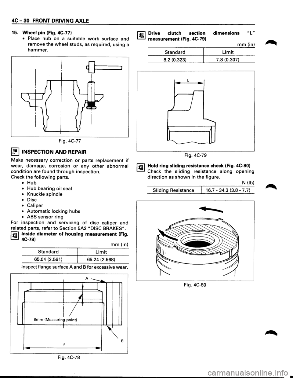
15. Wheel pin (Fig. 4C-77)
• Place
hub on a suitable work surface and
remove the
wheel studs, as required, using a
hammer.
Fig. 4C-77
I L•IINSPECTION AND REPAIR
Make necessary correction or parts replacement if
wear, damage, corrosion or any other abnormal
condition are found through inspection.
Check
the following parts.
• Hub
• Hub bearing oil seal
• Knuckle spindle
•
Disc
• Caliper
•
Automatic locking hubs
• ABS sensor ring
For inspection and servicing
of disc caliper and
related parts, refer to Section 5A2 "DISC BRAKES".
rfil Inside diameter of housing measurement (Fig.
~ 4C-78)
mm(in)
Standard Limit
65.04 (2.561)
65.24 (2.568)
Inspect flange surface A and 8 for excessive wear.
A ---....
1 I
'-/ I
i/ 8mm (Measuring point) I I
~.
e
Fig. 4C-78
rfil Drive clutch section
~ measurement (Fig. 4C-79)
Standard
8.2 (0.323)
L
Fig. 4C-79 dimensions
ulu
mm(in)
Limit
7.8
(0.307)
1@ 1 Hold ring sliding resistance check (Fig. 4C-80)
Check the sliding resistance along opening
direction as shown in the figure.
N (lb)
Sliding Resistance 16.7-34.3 (3.8-7.7)
......
Fig. 4C-80
Page 323 of 1928
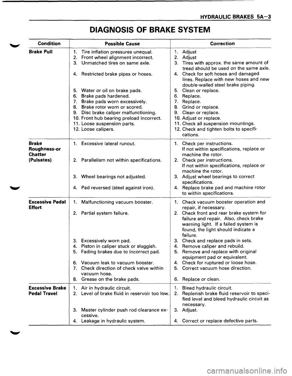
HYDRAULIC BRAKES 5A-3
DIAGNOSIS OF BRAKE SYSTEM
Condition
Possible Cause Correction
Brake
Pull 1. Tire inflation pressures unequal. 1. Adjust
2. Front wheel alignment incorrect. 2. Adjust
3. Unmatched tires on same axle. 3. Tires with approx. the same amount of
tread should be used on the same axle.
4. Restricted brake pipes or hoses. 4. Check for soft hoses and damaged
lines. Replace with new hoses and new
double-walled steel brake piping.
5. Water or oil on brake pads. 5. Clean or replace.
6. Brake pads hardened. 6. Replace.
7. Brake pads worn excessively. 7. Replace.
8. Brake rotor worn or scored. 8. Grind or replace.
9. Disc brake caliper malfunctioning. 9. Clean or replace.
10. Front hub bearing preload incorrect. 10. Adjust or replace.
11. Loose suspension parts. 11. Check all suspension mountings.
12. Loose
calipers. 12. Check and tighten bolts to specifi-
cations.
Brake 1. Excessive lateral runout. 1. Check per instructions.
Roughness-or If not within specifications, replace or
Chatter machine the rotor.
(Pulsates) 2. Parallelism not within specifications. 2. Check per instructions.
If not within specifications, replace or
machine the rotor.
3. Wheel bearings not adjusted. 3. Adjust wheel bearings to correct
specifications.
4. Pad reversed (steel against iron). 4. Replace brake pad and machine rotor
to within specifications.
Excessive Pedal 1. Malfunctioning vacuum booster. 1. Check vacuum booster operation and
Effort repair, if necessary.
2. Partial system failure. 2. Check front and rear brake system for
failure and repair. Also, check brake
warning
light. If a failed system
is
found, the
light should indicate a
failure.
3. Excessively worn pad. 3. Check and replace pads in sets.
4. Piston in caliper stuck or sluggish. 4. Remove caliper and rebuild.
5. Fading brakes due to incorrect pad. 5. Remove and replace with original
equipment pad or equivalent.
6. Vacuum leak to vacuum booster. 4. Check for ruptured or loose hose.
7. Check direction of check valve within 5. Correct vacuum hose direction.
vacuum hose.
8. Grease on the brake pads. 6. Replace or clean.
Excessive Brake 1. Air in hydraulic circuit. 1. Bleed hydraulic circuit.
Pedal Travel 2. Level of brake fluid in reservoir too low. 2. Replenish brake fluid reservoir to speci-
fied
level and bleed hydraulic circuit as
necessary.
3. Master cylinder push rod clearance ex-3. Adjust.
cessive.
4. Leakage in hydraulic system. 4. Correct or replace defective parts.
Page 324 of 1928
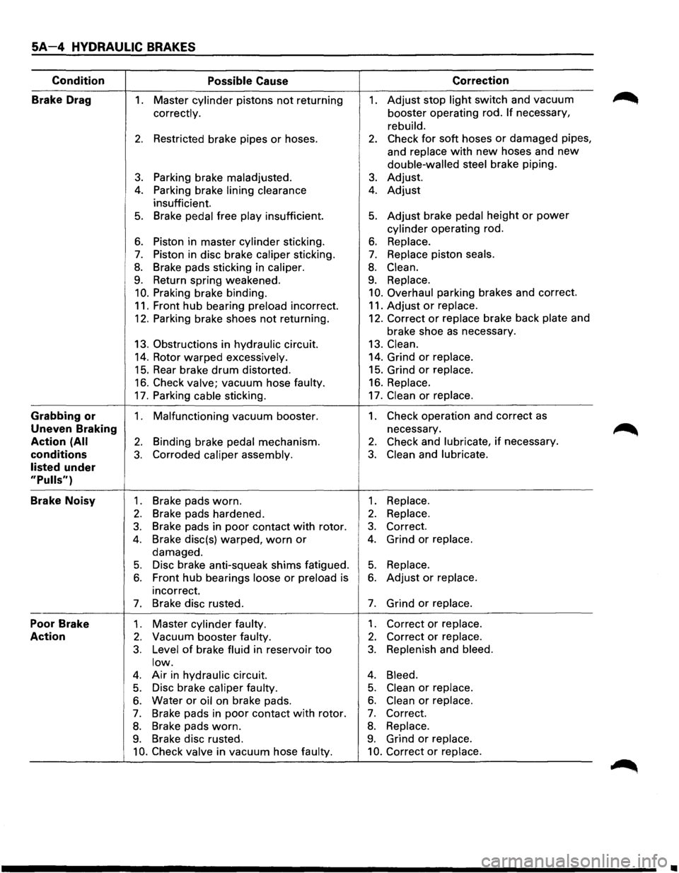
SA-4 HYDRAULIC BRAKES
Condition Possible Cause Correction
Brake Drag
1. Master cylinder pistons not returning 1. Adjust stop light switch and vacuum
correctly. booster operating rod. If necessary,
rebuild.
2. Restricted brake pipes or hoses. 2. Check for soft hoses or damaged pipes,
and
replace with new hoses and new
double-walled steel brake piping.
3. Parking brake maladjusted. 3. Adjust.
4. Parking brake lining clearance 4. Adjust
insufficient.
5. Brake pedal free play insufficient. 5. Adjust brake pedal height or power
cylinder operating rod.
6. Piston in master cylinder sticking. 6. Replace.
7. Piston in disc brake caliper sticking. 7. Replace piston seals.
8. Brake pads sticking in caliper. 8. Clean.
9. Return spring weakened. 9. Replace.
10. Praking brake binding. 10. Overhaul parking brakes and correct.
11. Front hub bearing preload incorrect. 11.
Adjust or replace.
12. Parking brake shoes not returning. 12.
Correct or replace brake back plate and
brake shoe
as necessary.
13. Obstructions in hydraulic circuit. 13. Clean.
14. Rotor warped excessively. 14.
Grind or replace.
15. Rear brake drum distorted. 15.
Grind or replace.
16. Check valve; vacuum hose faulty. 16. Replace.
17. Parking cable sticking. 17. Clean or replace.
Grabbing
or 1. Malfunctioning vacuum booster. 1. Check operation and correct as
Uneven Braking necessary.
Action
(All 2. Binding brake pedal mechanism. 2. Check and lubricate, if necessary.
conditions
3. Corroded caliper assembly. 3. Clean and lubricate.
listed
under
"Pulls")
Brake Noisy 1 . Brake pads worn. 1. Replace.
2. Brake pads hardened. 2. Replace.
3. Brake pads in poor contact with rotor. 3. Correct.
4. Brake disc(s) warped, worn or 4. Grind or replace.
damaged.
5. Disc brake anti-squeak shims fatigued. 5. Replace.
6. Front hub bearings loose or preload is 6. Adjust or replace.
incorrect.
7. Brake disc rusted. 7. Grind or replace.
Poor Brake 1. Master cylinder faulty. 1. Correct or replace.
Action 2. Vacuum booster faulty. 2. Correct or replace.
3. Level of brake fluid in reservoir too 3. Replenish and bleed.
low.
4. Air in hydraulic circuit. 4. Bleed.
5. Disc brake caliper faulty. 5. Clean or replace.
6. Water or oil on brake pads. 6. Clean or replace.
7. Brake pads in poor contact with rotor. 7. Correct.
8. Brake pads worn. 8. Replace.
9. Brake disc rusted. 9. Grind or replace.
10. Check valve in vacuum hose faulty. 10. Correct or replace.
•
Page 326 of 1928
5A-6 HYDRAULIC BRAKES
NOTE:
Do not allow the fluid level in the reservoir to go below
the half-way mark.
12. Reconnect the brake pipe
(j) to the master
cylinder and tighten the pipe.
13. Depress the brake pedal
slowly once and hold it
depressed.
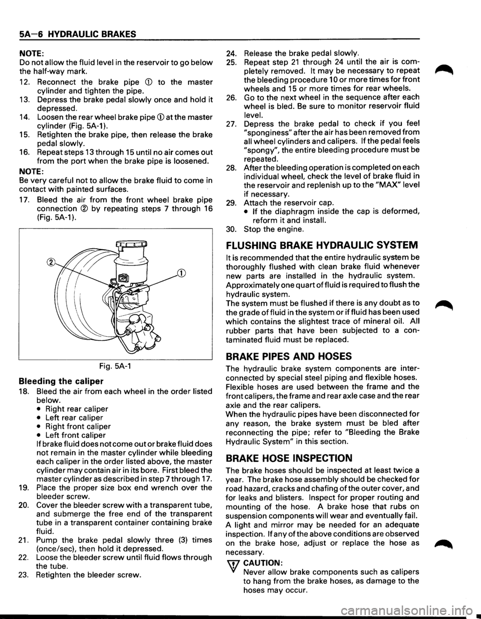
14. Loosen the rear wheel brake pipe (j) at the master
cylinder (Fig. 5A-1).
15. Retighten the brake pipe, then release the brake
pedal
slowly.
16. Repeat steps 13 through 15 until no air comes out
from the port when the brake pipe is loosened.
NOTE:
Be very careful not to allow the brake fluid to come in
contact
with painted surfaces.
17. Bleed the air from the front wheel brake pipe
connection
® by repeating steps 7 through 16
(Fig.
5A-1 ).
Fig. 5A-1
Bleeding the caliper
18. Bleed the air from each wheel in the order listed
below.
• Right rear caliper
• Left rear caliper
• Right front caliper
• Left front caliper
If brake fluid does not come out or brake fluid does
not remain in the master cylinder while bleeding
each
caliper in the order listed above, the master
cylinder may contain air in its bore. First bleed the
master cylinder
as described in step 7 through 17.
19.
Place the proper size box end wrench over the
bleeder screw.
20. Cover the bleeder screw with a transparent tube,
and submerge the free end
of the transparent
tube in a transparent container containing brake
fluid.
21. Pump the brake pedal slowly three (3) times
(once/sec), then
hold it depressed.
22. Loose the bleeder screw until fluid flows through
the tube.
23. Retighten the bleeder screw.
24. Release the brake pedal slowly.
25. Repeat step 21 through 24 until the air is com
pletely removed.
It may be necessary to repeat
the bleeding procedure
10 or more times for front
wheels and 15 or more times for rear wheels.
26. Go to the next wheel in the sequence after each
wheel is bled.
Be sure to monitor reservoir fluid
level.
27. Depress the brake pedal to check if you feel
"sponginess" after the air has been removed from
all wheel cylinders and calipers. If the pedal feels
"spongy", the entire bleeding procedure must be
repeated.
28. After the bleeding operation is completed on each
individual wheel, check the level
of brake fluid in
the reservoir and replenish up to the
"MAX" level
if necessary.
29. Attach the reservoir cap.
• If the diaphragm inside the cap is deformed,
reform
it and install.
30. Stop the engine.
FLUSHING BRAKE HYDRAULIC SYSTEM
It is recommended that the entire hydraulic system be
thoroughly flushed with clean brake fluid whenever
new parts are
installed in the hydraulic system.
Approximately one quart
of fluid is required to flush the
hydraulic system.
The system
must be flushed if there is any doubt as to
the grade
of fluid in the system or iffluid has been used
which contains the
slightest trace of mineral oil. All
rubber parts that have been subjected to a con
taminated fluid
must be replaced.
BRAKE PIPES AND HOSES
The hydraulic brake system components are inter
connected
by special steel piping and flexible hoses.
Flexible hoses are used between the frame and the
front calipers, the frame and rear axle case and the rear
axle and the rear calipers.
When the hydraulic pipes have been disconnected
for
any reason, the brake system must be bled after
reconnecting the pipe; refer to
"Bleeding the Brake
Hydraulic
System" in this section.
BRAKE HOSE INSPECTION
The brake hoses should be inspected at least twice a
year. The brake hose assembly should
be checked for
road hazard, cracks and chafing ofthe outer cover, and
for leaks and blisters. Inspect for proper routing and
mounting
of the hose. A brake hose that rubs on
suspension components
will wear and eventually fail.
A light and mirror may be needed for an adequate
inspection.
If any of the above conditions are observed
on the brake hose, adjust
or replace the hose as
necessary.
\fl CAUTION:
'V Never allow brake components such as calipers
to hang from the brake hoses, as damage to the
hoses may occur.
Page 339 of 1928
HYDRAULIC BRAKES SA-19
UNIT REPAIR
MASTER CYLINDER
• The master cylinder is not repairable and must
be replaced as complete assembly if found
defective.
INSPECTION
Excessive brake pedal travel, malfunction or dragging
brake suggests
that the master cylinder is defective. In
such cases perform the following visual check.
IL•I Visual check
Make parts replacement as required if wear, distortion,
nicks, cuts, corrosion,
or other abnormal conditions
are
found through the following parts inspection;
• Master cylinder body
• Fluid reservoir
• 0-ring
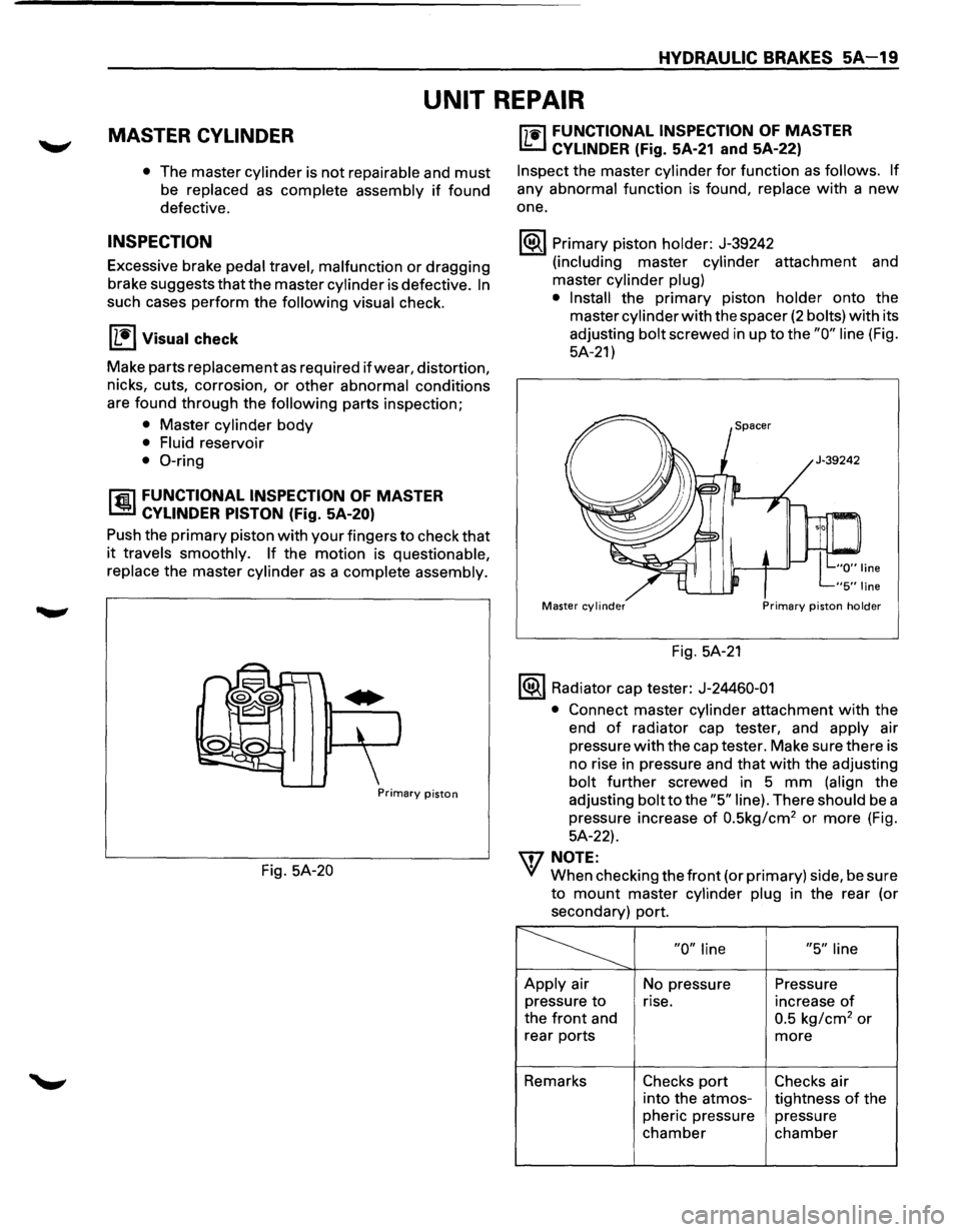
rfil FUNCTIONAL INSPECTION OF MASTER
l..!aJ CYLINDER PISTON (Fig. SA-20)
Push the primary piston with your fingers to check that
it travels smoothly. If the motion is questionable,
replace
the master cylinder as a complete assembly.
Primary piston
Fig. 5A-20
["j"1i"l FUNCTIONAL INSPECTION OF MASTER
I..!:::..J CYLINDER (Fig. 5A-21 and 5A-22)
Inspect the master cylinder for function as follows. If
any abnormal function is found, replace with a new
one.
1®.1 Primary piston holder: J-39242
(including master cylinder attachment and
master
cylinder plug)
• Install
the primary piston holder onto the
master
cylinder with the spacer (2 bolts) with its
adjusting
bolt screwed in up to the "0" line (Fig.
5A-21)
Master cylinder Primary piston holder
Fig. 5A-21
1®.1 Radiator cap tester: J-24460-01
•
Connect master cylinder attachment with the
end
of radiator cap tester, and apply air
pressure
with the cap tester. Make sure there is
no rise in pressure and
that with the adjusting
bolt further screwed in 5 mm (align the
adjusting
bolt to the "5" line). There should be a
pressure increase
of 0.5kg/cm2 or more (Fig.
5A-22).
\f7 NOTE:
VI When checking the front (or primary) side, be sure
to mount master cylinder plug in the rear (or
secondary) port.
~ "0" line "5" line
Apply air
No pressure Pressure
pressure
to rise. increase of
the front and 0.5 kg/cm2 or
rear ports more
Remarks Checks port Checks air
into the atmos-
tightness
of the
pheric pressure pressure
chamber chamber
Page 347 of 1928
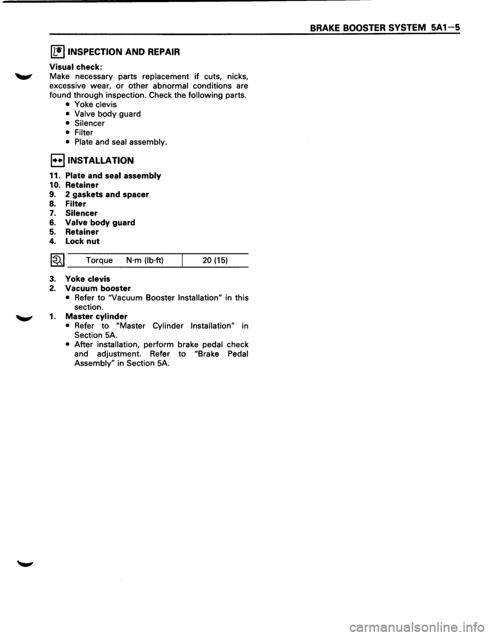
[1!) INSPECTION AND REPAIR
Visual check:
'-"' Make necessary parts replacement if cuts, nicks,
excessive wear,
or other abnormal conditions are
found through inspection.
Check the following parts.
• Yoke clevis
• Valve
body guard
• Silencer
• Filter
• Plate
and seal assembly.
I••IINSTALLATION
11. Plate and seal assembly
1 0. Retainer
9. 2 gaskets and spacer
8. Filter
7. Silencer
6. Valve body guard
5. Retainer
4. Lock nut
20 (15) 1~1 Torque N·m (lb·ft) ----------1....---
3. Yoke clevis
2. Vacuum booster
• Refer to "Vacuum Booster Installation" in this
section.
'-"" 1. Master cylinder
• Refer to "Master Cylinder Installation" in
Section 5A.
• After installation, perform brake pedal check
and adjustment. Refer
to "Brake Pedal
Assembly" in Section 5A.
BRAKE BOOSTER SYSTEM 5A 1-5