ISUZU TROOPER 1995 Workshop Manual
Manufacturer: ISUZU, Model Year: 1995, Model line: TROOPER, Model: ISUZU TROOPER 1995Pages: 1928
Page 1431 of 1928
CHASSIS ELECTRICAL 8-241
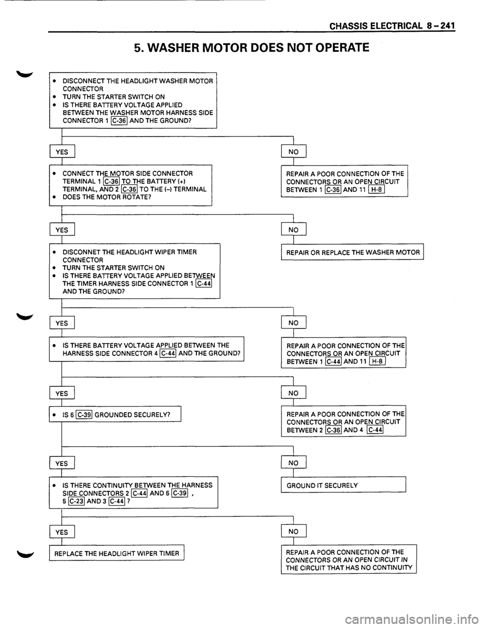
5. WASHER MOTOR DOES NOT OPERATE
• DISCONNECT THE HEADLIGHT WASHER MOTOR
CONNECTOR
• TURN THE STARTER SWITCH ON
• IS THERE BATTERY VOLTAGE APPLIED BETWEEN THE WASHER MOTOR HARNESS SIDE
CONNECTOR 1 IC-361 AND THE GROUND?
I
YES I NO I I I
• CONNECT THE MOTOR SIDE CONNECTOR REPAIR A POOR CONNECTION OF THE TERMINAL 1IC-36I TO THE BATTERY !+l CONNECTORS OR AN OPEN CIRCUIT
TERMINAL, AND 2IC-36I TO THE H TERMINAL BETWEEN 1IC-36IAND 11! H-BI
• DOES THE MOTOR ROTATE?
I
YES I NO I
I
• DISCONNET THE HEADLIGHT WIPER TIMER REPAIR OR REPLACE THE WASHER MOTOR I CONNECTOR
• TURN THE STARTER SWITCH ON
• IS THERE BATTERY VOLTAGE APPLIED BETWEEN
THE
TIMER HARNESS SIDE CONNECTOR 1IC-44I AND THE GROUND?
I
YES I NO I
I
• IS THERE BATTERY VOLTAGE APPLIED BETWEEN THE REPAIR A POOR CONNECTION OF THE HARNESS SIDE CONNECTOR 4IC-44I AND THE GROUND? CONNECTORS OR AN OPEN CIRCUIT
BETWEEN 1 lc-441 AND 11 I H-al
I
YES I NO I I I
• IS sl C-391 GROUNDED SECURELY? I REPAIR A POOR CONNECTION OF THE CONNECTORS OR AN OPEN CIRCUIT
BETWEEN 2IC-36I AND 4 IC-441
I
YES I NO J
I
• IS THERE CONTINUITY BETWEEN THE HARNESS GROUND IT SECURELY
SIDE CONNECTORS 2IC-44! AND s!C-39! ,
s!C-23! AND 3!C-44!?
I
YES I NO I
I
REPLACE THE HEADLIGHT WIPER TIMER I REPAIR A POOR CONNECTION OF THE CONNECTORS OR AN OPEN CIRCUIT IN THE CIRCUIT THAT HAS NO CONTINUITY
Page 1432 of 1928
8-242 CHASSIS ELECTRICAL
STARTER SWITCH
Refer to "START AND CHARGING" of this section.
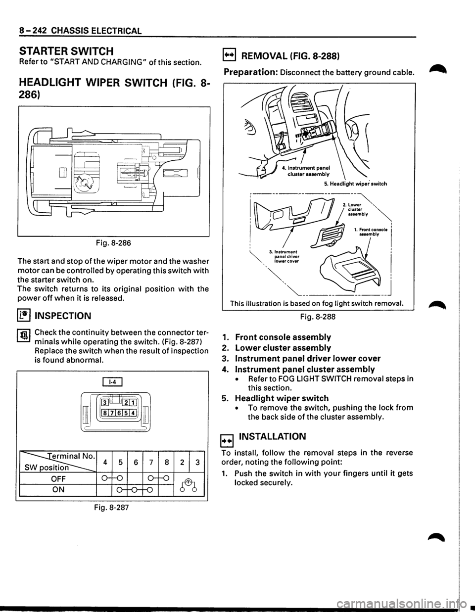
HEADLIGHT WIPER SWITCH (FIG. 8-
286)
Fig. 8-286
The start and stop
of the wiper motor and the washer
motor can be controlled by operating this switch with
the starter switch on.
The switch returns to its
original position with the
power off when it is released.
(1!] INSPECTION
rfiil Check the continuity between the connector ter
L:::.I minals while operating the switch. (Fig. 8-287)
Replace the switch when the result of inspection
is
found abnormal.
[ill
[I
roo8___8tillJ1
lsl7lslsi4IJ ill
' )
~· s 4 5 6 7 8 2 1 3
OFF o--o o-f-o
~ ON o-f-0--f-0
Fig. 8-287
B REMOVAL (FIG. 8-288)
Preparation: Disconnect the battery ground cable. ~
This illustration is based on fog light switch removal.
Fig. 8-288
1.
Front console assembly
2. Lower cluster assembly
3. Instrument panel driver lower cover
4. Instrument panel cluster assembly
• Refer to FOG LIGHT SWITCH removal steps in
this section.
5.
Headlight wiper switch
• To remove the switch, pushing the lock from
the back side of the cluster assembly.
B INSTALLATION
To install, follow the removal steps in the reverse
order, noting the
following point:
1. Push the switch in with your fingers until it gets
locked securely.
•
Page 1433 of 1928
HEADLIGHT WIPER ARM & BLADE
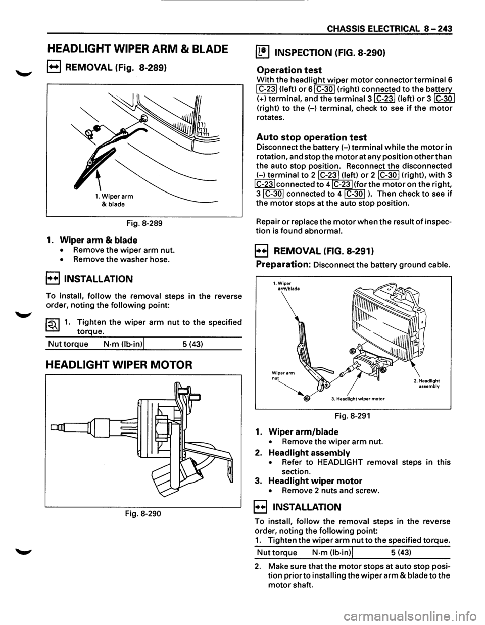
B REMOVAL (Fig. 8-289)
1. Wiper arm
&
blade
Fig. 8-289
1. Wiper arm & blade
• Remove the wiper arm nut.
• Remove the washer hose.
B INSTALLATION
To install, follow the removal steps in the reverse
order, noting
the following point:
~~~1. Tighten the wiper arm nut to the specified
torque.
Nut torque N·m Ob·in)l 5 (43)
HEADLIGHT WIPER MOTOR
Fig. 8-290
CHASSIS ELECTRICAL 8-243
~ INSPECTION (FIG. 8-290)
Operation test
With the headlight wiper motor connector terminal 6
I C-231 (left) or 61 C-30 I (right) connected to the ba~
(+)terminal, and the termina13IC-23I (left) or 3 ~
(right) to the (-) terminal, check to see if the motor
rotates.
Auto stop operation test
Disconnect the battery(-) terminal while the motor in
rotation, and stop the
motor at any position other than
the auto stop position. Reconnect the disconnected
(-)terminal to 2 C-23 (left) or 2 IC-30 I (right), with 3
IC-23Iconnected to 4 C-23 (for the motor on the right,
3IC-30I connected to 4IC-30I ). Then check to see if
the motor stops at the auto stop position.
Repair
or replace the motor when the result of inspec
tion is found abnormal.
B REMOVAL (FIG. 8-291)
Preparation: Disconnect the battery ground cable.
1.Wiper arm/blade
Wiper arm nut
~ 3. Headlight wiper motor
Fig. 8-291
1. Wiper arm/blade
• Remove the wiper arm nut.
2. Headlight assembly
2. Headlight
assembly
• Refer to HEADLIGHT removal steps in this
section.
3. Headlight wiper motor
• Remove 2 nuts and screw.
B INSTALLATION
To install, follow the removal steps in the reverse
order, noting the
following point:
1. Tighten the wiper arm nut to the specified torque.
Nut torque N·m (lb·in)l 5 (43)
2. Make sure that the motor stops at auto stop posi
tion
prior to installing the wiper arm & blade to the
motor shaft.
Page 1434 of 1928
![ISUZU TROOPER 1995 Workshop Manual 8-244 CHASSIS ELECTRICAL
HEADLIGHT WASHER MOTOR
(b!] INSPECTION
Fig. 8-292
With the washer
motor connector 1 I C-361 connected
to the battery(+) terminal, and the connector 2 IC-361
to the](/img/61/57183/w960_57183-1433.png "ISUZU TROOPER 1995 Workshop Manual 8-244 CHASSIS ELECTRICAL
HEADLIGHT WASHER MOTOR
(b!] INSPECTION
Fig. 8-292
With the washer
motor connector 1 I C-361 connected
to the battery(+) terminal, and the connector 2 IC-361
to the")
8-244 CHASSIS ELECTRICAL
HEADLIGHT WASHER MOTOR
(b!] INSPECTION
Fig. 8-292
With the washer
motor connector 1 I C-361 connected
to the battery(+) terminal, and the connector 2 IC-361
to the battery (-) terminal, check to see if the motor
rotates smoothly. (Fig. 8-292)
Repair
or replace the motor when the result of inspec
tion is found abnormal.
E) REMOVAL AND INSTALLATION
1•+1 Refer to the removal and installation steps ofthe
windshield washer tank/motor under "WIND
SHIELD WIPER/WASHER
AND REAR WIPER/
WASHER"
in this section.
HEADLIGHT WIPER TIMER
B REMOVAL (FIG. 8-293)
Preparation: Disconnect the battery ground cable.
~Hdl"h··· 5. ea 19 t w1per timer
Fig. 8-293
1. Front console assembly
2. Lower cluster assembly
3. Glove box assembly
4. Instrument panel passenger lower cover
• Refer to INSTRUMENT PANEL ASSEMBLY in
Section 10 BODY.
5. Headlight wiper timer
B INSTALLATION
To install, follow the removal steps in the reverse
order.
Page 1435 of 1928

CHASSIS ELECTRICAL 8-245
MEMO
Page 1436 of 1928
8-246 CHASSIS ELECTRICAL
AUDIO, AUTO ANTENNA, CIGARETTE LIGHTER AND DIGITAL CLOCK
GENERAL DESCRIPTION
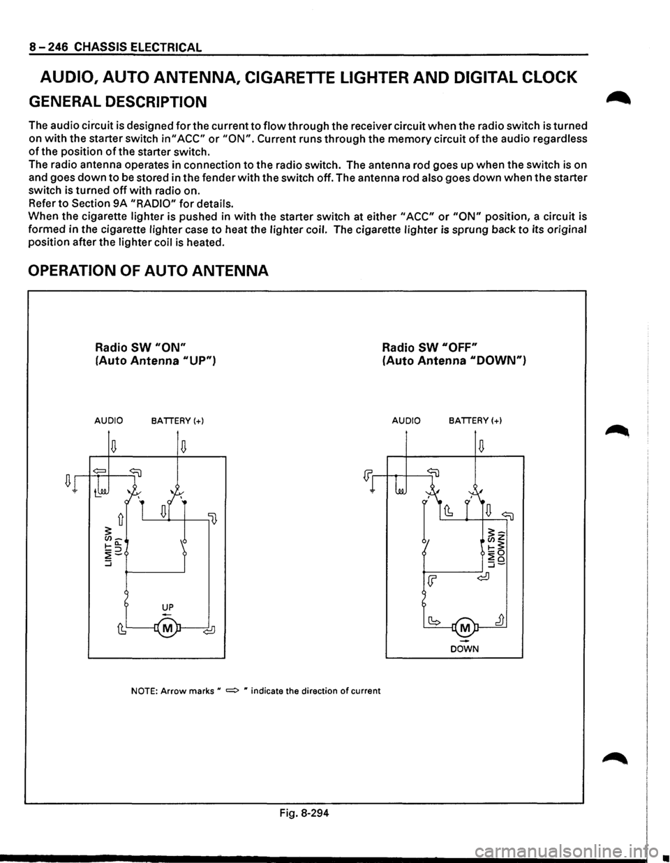
The audio circuit is designed for the current to flow through the receiver circuit when the radio switch is turned
on
with the starter switch in" ACC" or "ON". Current runs through the memory circuit of the audio regardless
of the position of the starter switch.
The radio antenna operates in connection
to the radio switch. The antenna rod goes up when the switch is on
and goes
down to be stored in the fender with the switch off. The antenna rod also goes down when the starter
switch is turned
off with radio on.
Refer
to Section 9A "RADIO" for details.
When the cigarette lighter is pushed in
with the starter switch at either "ACC" or "ON" position, a circuit is
formed in the cigarette lighter case
to heat the lighter coil. The cigarette lighter is sprung back to its original
position after the lighter coil
is heated.
OPERATION OF AUTO ANTENNA
Radio SW "ON"
(Auto Antenna "UP")
AUDIO BATTERY(+)
NOTE: Arrow marks u =:> " indicate the direction of current
Fig. 8-294
Radio SW "OFF"
(Auto Antenna "DOWN")
AUDIO BATTERY(+)
M
DOWN
•
Page 1437 of 1928
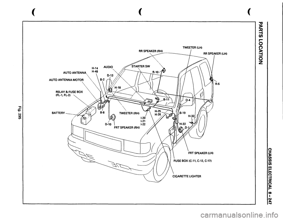
::!! cp ....,
AUTO
ANTENNA
AUTO
ANTENNA
MOTOR
RELAY
& FUSE
BOX
(FL-1,
FL-2)
BATTERY~
(
lWEETER
IRH)
FRT
SPEAKER
IRH)
1-20' 1-21 1-22
(
lWEETER
ILH)
FUSE
BOX
IC-11,
C-12,
C-17)
~ ~ r-0 0 ~ 0 z
(") :I: )> (I)
(I) c;; m ,... m ~ :a ~ ,... co I N ~
Page 1438 of 1928
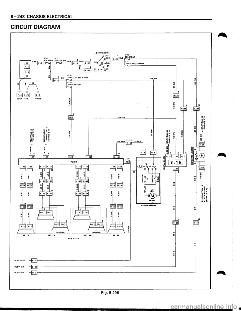
8-248 CHASSIS ELECTRICAL
CIRCUIT DIAGRAM
Fig. 8·296
•
Page 1439 of 1928
![ISUZU TROOPER 1995 Workshop Manual CONNECTOR LIST
~
~
Fig. 8-297
CHASSIS ELECTRICAL 8-249
[[[] lo-1ol
[]I] I R-101
I H-321 !GRADE Sl I H-481](/img/61/57183/w960_57183-1438.png "ISUZU TROOPER 1995 Workshop Manual CONNECTOR LIST
~
~
Fig. 8-297
CHASSIS ELECTRICAL 8-249
[[[] lo-1ol
[]I] I R-101
I H-321 !GRADE Sl I H-481")
CONNECTOR LIST
~
~
Fig. 8-297
CHASSIS ELECTRICAL 8-249
[[[] lo-1ol
[]I] I R-101
I H-321 !GRADE Sl I H-481
Page 1440 of 1928
![ISUZU TROOPER 1995 Workshop Manual 8-250 CHASSIS ELECTRICAL
DIAGNOSIS
1. CIGARETIE LIGHTER DOES NOT HEAT SUFFICIENTLY
• IS FUSE C-12 (20Al NORMAL? I
I
YES I NO I
I
• IS (]I] SECURELY GROUNDED? I REPLACE THE FUSE I
I
Y](/img/61/57183/w960_57183-1439.png "ISUZU TROOPER 1995 Workshop Manual 8-250 CHASSIS ELECTRICAL
DIAGNOSIS
1. CIGARETIE LIGHTER DOES NOT HEAT SUFFICIENTLY
• IS FUSE C-12 (20Al NORMAL? I
I
YES I NO I
I
• IS (]I] SECURELY GROUNDED? I REPLACE THE FUSE I
I
Y")
8-250 CHASSIS ELECTRICAL
DIAGNOSIS
1. CIGARETIE LIGHTER DOES NOT HEAT SUFFICIENTLY
• IS FUSE C-12 (20Al NORMAL? I
I
YES I NO I
I
• IS (]'I] SECURELY GROUNDED? I REPLACE THE FUSE I
I
YES I NO I
I
• REMOVE THE CIGARETTE LIGHTER GROUND IT SECURELY J • SET THE STARTER SWITCH TO EITHER uACCu OR uON"
POSITION
• IS THE BATTERY VOLTAGE APPLIED BETWEEN THE BIMETAL AT THE CENTER OF THE CASE AND THE CASE?
I
YES I NO
I
REPLACE THE CIGARETTE LIGHTER ASSEMBLy I REPAIR A POOR CONNECTION AT THE
CONNECTORS OR AN OPEN CIRCUIT BETWEEN
FUSE C-12 (20Al AND 1 ~
2. CIGARETTE LIGHTER DOES NOT SPRING OUT AFTER BEING
HEATED
REPLACE THE CIGARETTE LIGHTER
ASSEMBLY