ISUZU TROOPER 1995 Workshop Manual
Manufacturer: ISUZU, Model Year: 1995, Model line: TROOPER, Model: ISUZU TROOPER 1995Pages: 1928
Page 1441 of 1928
AUDIO
AUTO ANTENNA
Refer to Section 9A "RADIO" for details.
CIGARETTE LIGHTER
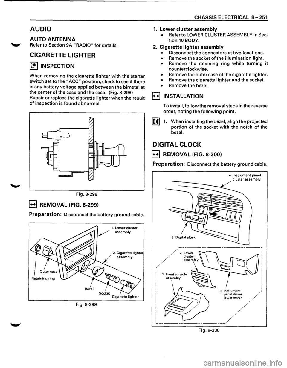
~ INSPECTION
When removing the cigarette lighter with the starter
switch set
to the "ACC" position, check to see if there
is any battery voltage applied between the bimetal at
the center
of the case and the case. (Fig. 8-298)
Repair
or replace the cigarette lighter when the result
of inspection is found abnormal.
Fig. 8-298
B REMOVAL (FIG. 8-299)
Preparation: Disconnect the battery ground cable.
Retaining ring
Fig. 8-299
CHASSIS ELECTRICAL 8-251
1. lower cluster assembly
• Refer to LOWER CLUSTER ASSEMBLY in Sec
tion 10 BODY.
2. Cigarette lighter assembly
• Disconnect the connectors at two locations.
• Remove the socket of the illumination light.
•
Remove the retaining ring while turning it
counterclockwise.
• Remove the outer case of the cigarette lighter.
• Remove the cigarette lighter and the socket.
• Remove the bezel.
I••! INSTALLATION
To install, follow the removal steps in the reverse
order, noting the
following point.
1. When installing the bezel, align the projected
portion
of the socket with the notch of the
bezel.
DIGITAL CLOCK
B REMOVAL (FIG. 8-300)
Preparation: Disconnect the battery ground cable.
Fig.
8-300
4. Instrument panel cluster assembly
Page 1442 of 1928
8-252 CHASSIS ELECTRICAL
1. Front console assembly
2. Lower cluster assembly
3. Instrument panel driver lower cover
4. Instrument panel cluster assembly
• Refer to FOG LIGHT SWITCH removal steps in
this section.
5. Digital clock
• To remove the clock, pushing the lock from the
back side
of the cluster assembly.
E) INSTALLATION
To install, follow the removal steps in the reverse
order.
Page 1443 of 1928
CHASSIS ELECTRICAL 8-253
MEMO
Page 1444 of 1928
8-254 CHASSIS ELECTRICAL
POWER DOOR MIRROR
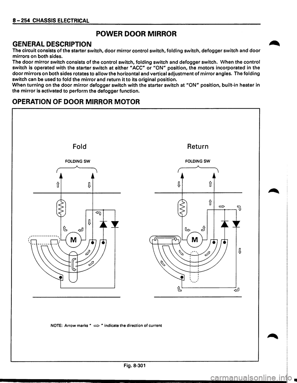
GENERAL DESCRIPTION
The circuit consists of the starter switch, door mirror control switch, folding switch, defogger switch and door
mirrors on both sides.
The
door mirror switch consists of the control switch, folding switch and defogger switch. When the control
switch is operated with the starter switch at either
"ACC" or "ON" position, the motors incorporated in the
door mirrors on both sides rotates to allow the horizontal and vertical adjustment of mirror angles. The folding
switch can
be used to fold the mirror and return it to its original position.
When turning on the
door mirror defogger switch with the starter switch at "ON" position, built-in heater in
the
mirror is activated to perform the defogger function.
OPERATION OF DOOR MIRROR MOTOR
Fold Return
FOLDING SW FOLDING SW
..---~A"""--
( '
---~.A.'---
( '
NOTE: Arrow marks " ~ " indicate the direction of current
Fig. 8-301
•
Page 1445 of 1928
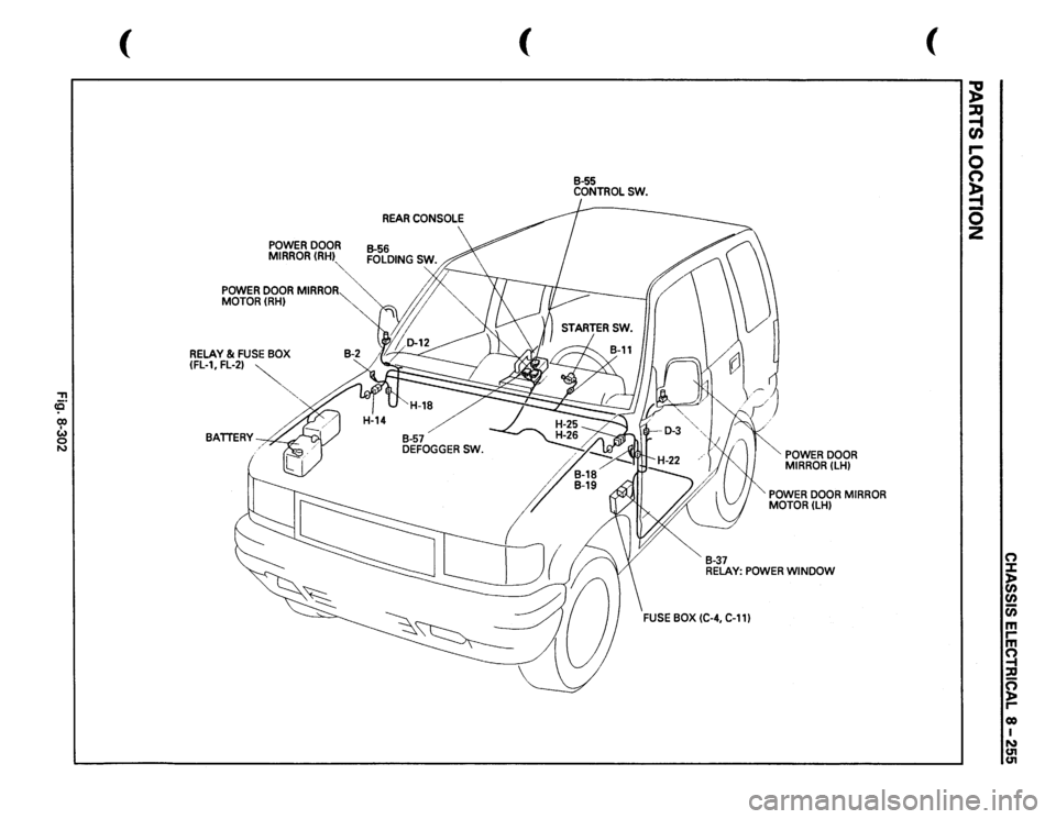
-n ce· 0) I w 0 N
(
POWER
DOOR
MIRROR(RHI
""~
POWER
DOOR
MIRROR
MOTOR(RH)
RELAY
& FUSE
BOX
(FL-1,
FL-2)
~
"",
BATTERY~
(
REAR
CONSOLE
B-55 CONTROLSW.
B-37
POWER
DOOR
MIRROR
(LH)
". POWER
DOOR
MIRROR
MOTOR(LH)
RELAY:
POWER
WINDOW
(
~ ~ r-0 (') ~ -0 z
(") ::I: )> en
en iii m rm ~ :a n )> r-eo I N U'1 U'1
Page 1446 of 1928
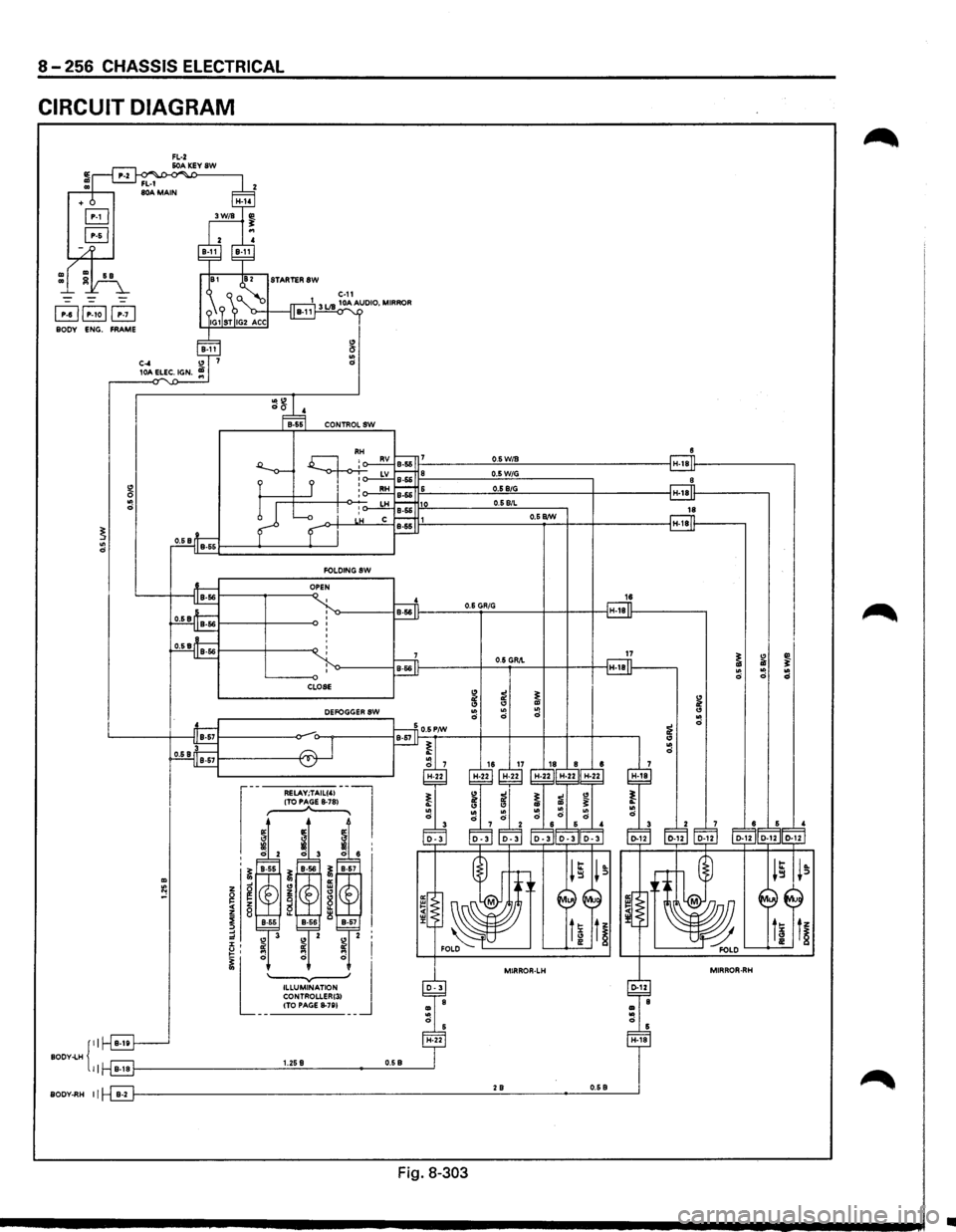
8 -256 CHASSIS ELECTRICAL
CIRCUIT DIAGRAM
"' ..
~RB BODY ENG. FRAME
g .. d
~ .. d
{
II BODY-LH II
BODY-RH II
g .. d
DEFOGGERSW
0.6W/9 0.6W/G
0.69/G 0.69/L
0.6
GR/G
0.6 GR,\.
)£ II!
" " .. .. d d
28
Fig. 8-303
H·18
H·18
18 0.6 BIN H-18
16
~ l: ~ ..
.. .. d d
d
~ )£ ~ " ..
~ d
" .. d
1i
0.6 B
•
Page 1447 of 1928
![ISUZU TROOPER 1995 Workshop Manual CHASSIS ELECTRICAL 8-257
CONNECTOR LIST
[E]Is-191 I B-111 I s-1sl I s-ssl
l9lm •
I s-ssl I B-571 []Ill 0·121 I H-141
•
Q 1111
~ ~ mtilil • 8 6
IH-18llH·22l [EJ[EJ m:J[BJ[EJ I P-10 I](/img/61/57183/w960_57183-1446.png "ISUZU TROOPER 1995 Workshop Manual CHASSIS ELECTRICAL 8-257
CONNECTOR LIST
[E]Is-191 I B-111 I s-1sl I s-ssl
l9lm •
I s-ssl I B-571 []Ill 0·121 I H-141
•
Q 1111
~ ~ mtilil • 8 6
IH-18llH·22l [EJ[EJ m:J[BJ[EJ I P-10 I")
CHASSIS ELECTRICAL 8-257
CONNECTOR LIST
[E]Is-191 I B-111 I s-1sl I s-ssl
l9lm •
I s-ssl I B-571 []Ill 0·121 I H-141
•
Q 1111
~ ~ mtilil • ' 8 6
IH-18llH·22l [EJ[EJ m:J[BJ[EJ I P-10 I
Fig. 8·304
Page 1448 of 1928
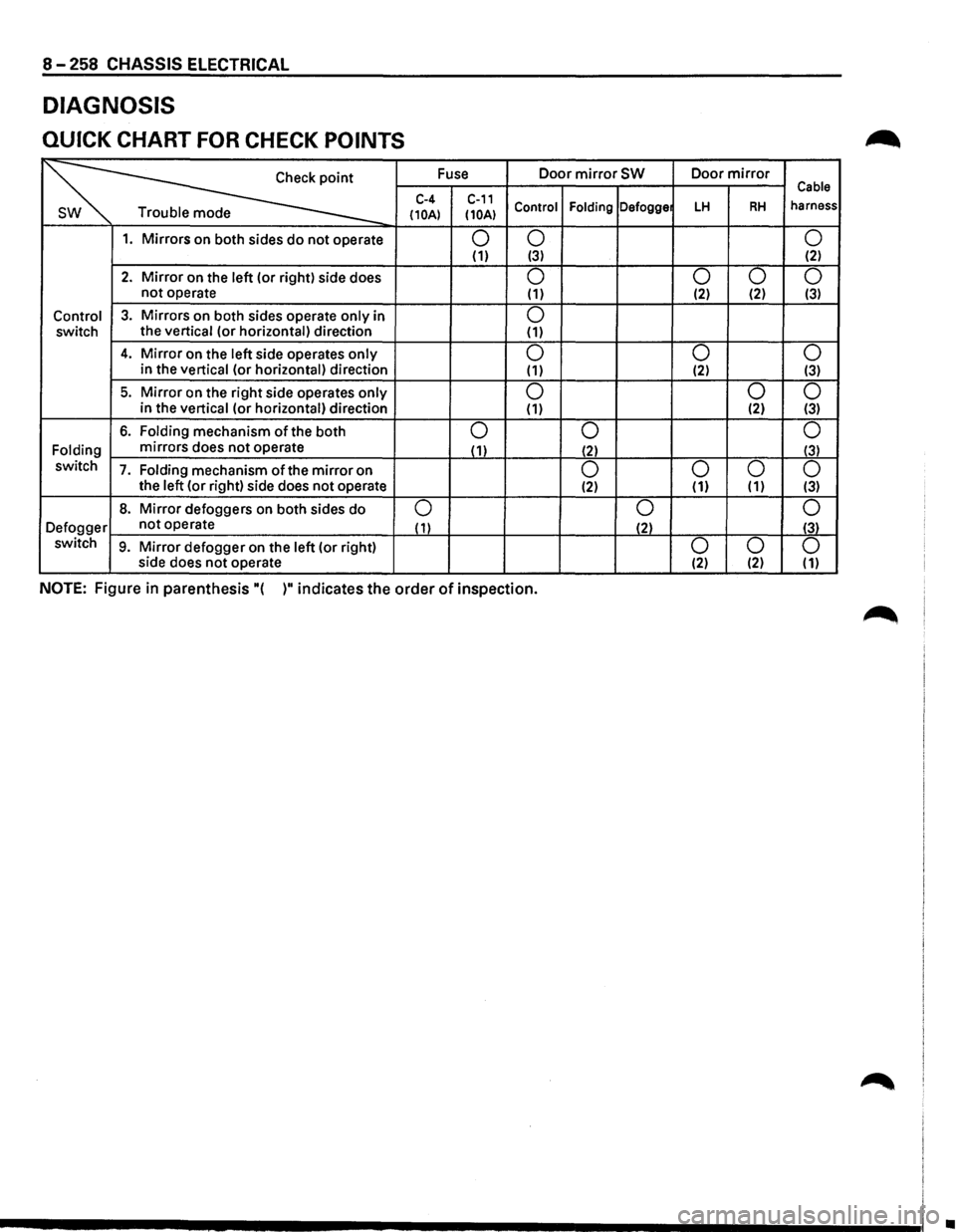
8 -258 CHASSIS ELECTRICAL
DIAGNOSIS
QUICK CHART FOR CHECK POINTS
~
Fuse Door mirror SW Door mirror Cable C-4 C-11 Control Folding Defogge LH RH harness Trouble mode (10A) (10A)
1. Mirrors on both sides do not operate 0 0
0 (1) (3) (2)
2. Mirror on the left (or right) side does 0 0 0 0 not operate (1) (2) (2) (3)
Control 3. Mirrors on both sides operate only in 0 switch the vertical
(or horizontal) direction (1)
4. Mirror on the left side operates only 0 0 0 in
the vertical (or horizontal) direction (1) (2) (3)
5. Mirror on
the right side operates only 0 0 0 in the vertical (or horizontal) direction (1) (2) (3)
6. Folding
mechanism of the both 0 0 0
Folding mirrors
does not operate (1)
(2) (3)
switch 7. Folding mechanism ofthe mirror on 0 0
0
0 the left (or right) side does not operate (2) (1) (1) (3)
8. Mirror defoggers
on both sides do 0 0
0
Defogger not
operate ( 1) (2) (3)
switch 9. Mirror defogger on the left (or right) 0 0
0 side does not operate (2) (2) (1)
NOTE: Figure in parenthesis "( )" indicates the order of inspection.
•
Page 1449 of 1928
CHASSIS ELECTRICAL 8-259
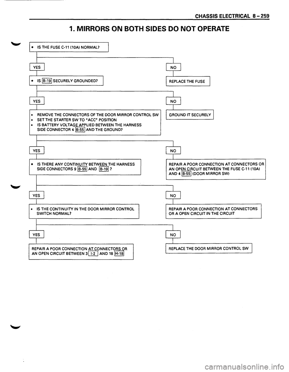
1. MIRRORS ON BOTH SIDES DO NOT OPERATE
• IS THE FUSE C-11 (10AI NORMAL? I
I
YES
I NO I
I
• IS IB-191 SECURELY GROUNDED? I REPLACE THE FUSE I
I
YES
j NO I
I
• REMOVE THE CONNECTORS OF THE DOOR MIRROR CONTROL SW GROUND IT SECURELY I
• SET THE STARTER SW TO "ACC" POSITION
• IS BATTERY VOLTAGE APPLIED BETWEEN THE HARNESS
SIDE
CONNECTOR 4IB-55I AND THE GROUND?
I
YES
j NO I
I
• IS THERE ANY CONTINUITY BETWEEN THE HARNESS REPAIR A POOR CONNECTION AT CONNECTORS OR
SIDE CONNECTORS siB-551 AND IB-191? AN OPEN CIRCUIT BETWEEN THE FUSE C-11 (10AI
AND 4IB-55I (DOOR MIRROR SWI
I
YES
I NO I
I
• IS THE CONTINUITY IN THE DOOR MIRROR CONTROL REPAIR A POOR CONNECTION AT CONNECTORS
SWITCH NORMAL? OR A OPEN CIRCUIT IN THE CIRCUIT
I
YES
I NO I
I
REPAIR
A POOR CONNECTION AT CONNECTORS OR REPLACE THE DOOR MIRROR CONTROL SW I
AN OPEN CIRCUIT BETWEEN 3@] AND 18IH-18I
Page 1450 of 1928
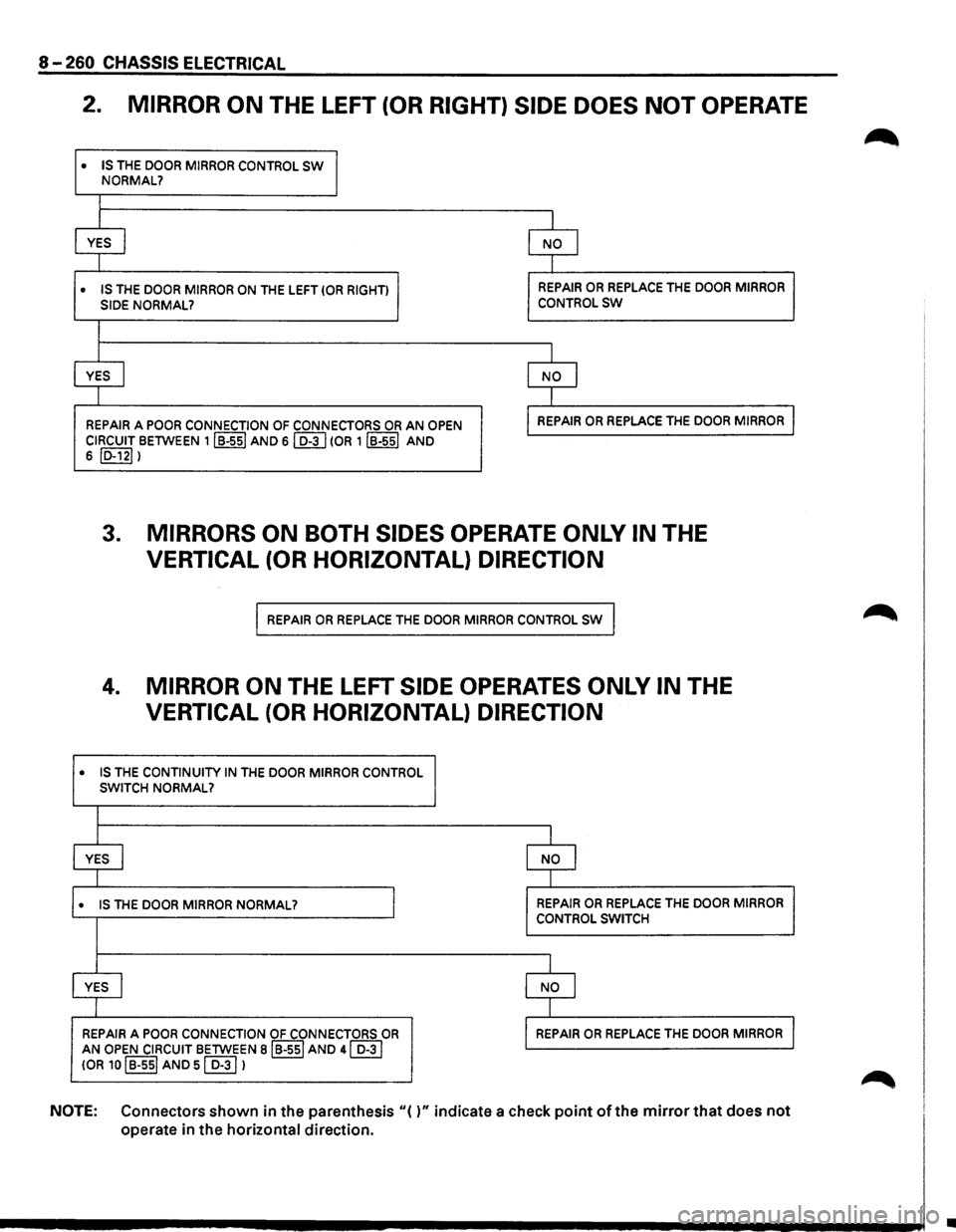
8-260 CHASSIS ELECTRICAL
2. MIRROR ON THE LEFT (OR RIGHT) SIDE DOES NOT OPERATE
• IS THE DOOR MIRROR CONTROL SW
•
NORMAL?
I
I
I
YES I NO I
I I
IS THE DOOR MIRROR ON THE LEFT (OR RIGHT) REPAIR OR REPLACE THE DOOR MIRROR
SIDE NORMAL? CONTROLSW
I
I I
YES I NO I
1 I
REPAIR A POOR CONNECTION OF CONNECTORS OR AN OPEN REPAIR OR REPLACE THE DOOR MIRROR
CIRCUIT BETWEEN 1IB-ssl AND sl D-3 I (OR 1 IB-551 AND
6 ID-121 I
3. MIRRORS ON BOTH SIDES OPERATE ONLY IN THE
VERTICAL (OR HORIZONTAL) DIRECTION
REPAIR OR REPLACE THE DOOR MIRROR CONTROL SW
4. MIRROR ON THE LEFT SIDE OPERATES ONLY IN THE
VERTICAL (OR HORIZONTAL) DIRECTION
• IS THE CONTINUITY IN THE DOOR MIRROR CONTROL SWITCH NORMAL?
I
YES I NO I
I
• IS THE DOOR MIRROR NORMAL? I REPAIR OR REPLACE THE DOOR MIRROR
CONTROL SWITCH
I
YES I NO I
I
REPAIR A POOR CONNECTION OF CONNECTORS OR REPAIR OR REPLACE THE DOOR MIRROR
AN OPEN CIRCUIT BETWEEN BIB-551 AND 41 D-31
!OR 10 I B-ssl AND sl D-31 1
NOTE: Connectors shown in the parenthesis "( )" indicate a check point of the mirror that does not
operate in the horizontal direction.
•