ISUZU TROOPER 1995 Workshop Manual
Manufacturer: ISUZU, Model Year: 1995, Model line: TROOPER, Model: ISUZU TROOPER 1995Pages: 1928
Page 1451 of 1928
CHASSIS ELECTRICAL 8-261
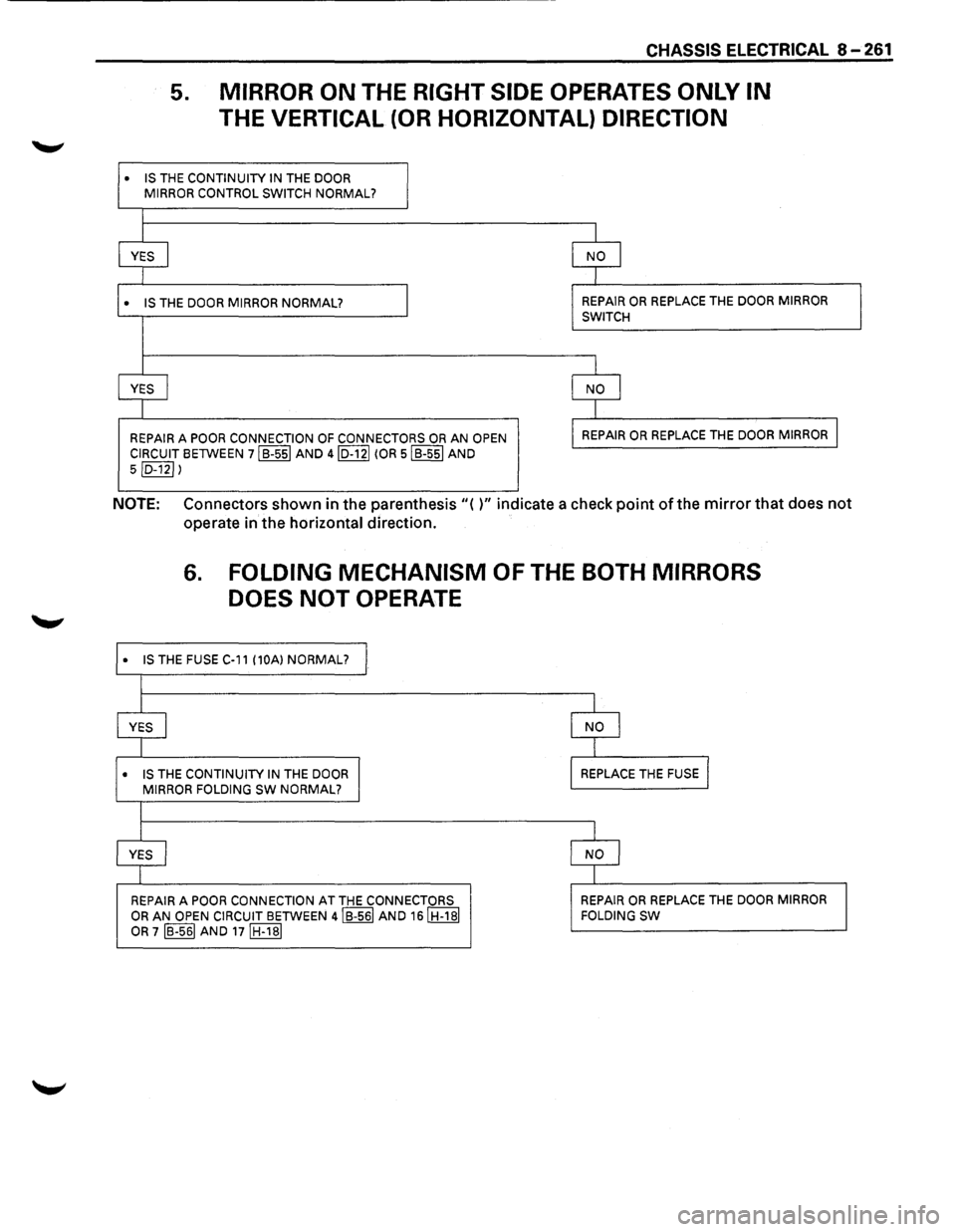
5. MIRROR ON THE RIGHT SIDE OPERATES ONLY IN
THE VERTICAL (OR HORIZONTAL) DIRECTION
• IS THE CONTINUITY IN THE DOOR
MIRROR CONTROL SWITCH NORMAL?
l
YES I NO I
1
• IS THE DOOR MIRROR NORMAL? REPAIR OR REPLACE THE DOOR MIRROR
SWITCH
I
YES
I NO I
1
REPAIR A POOR CONNECTION OF CONNECTORS OR AN OPEN REPAIR OR REPLACE THE DOOR
MIRROR I
CIRCUIT BETWEEN 7IB-55I AND 4ID-12I (OR 5IB-55I AND
5ID-12I l
NOTE: Connectors shown in the parenthesis"( )" indicate a check point of the mirror that does not
operate in the horizontal direction.
•
•
6. FOLDING MECHANISM OF THE BOTH MIRRORS
DOES NOT
OPERATE
IS THE FUSE C-11 (10A) NORMAL? I
I
L I
YES
I NO I
I T
IS THE CONTINUITY IN THE DOOR I MIRROR FOLDING SW NORMAL? REPLACE THE
FUSE l
I
I l
YES j NO l
I I
REPAIR
A POOR CONNECTION AT THE CONNECTORS REPAIR OR REPLACE THE DOOR
MIRROR
OR AN OPEN CIRCUIT BETWEEN 4IB-56I AND 16IH-1BI
OR 7 IB-561 AND 17IH-1BI FOLDING
SW
Page 1452 of 1928
8 -262 CHASSIS ELECTRICAL
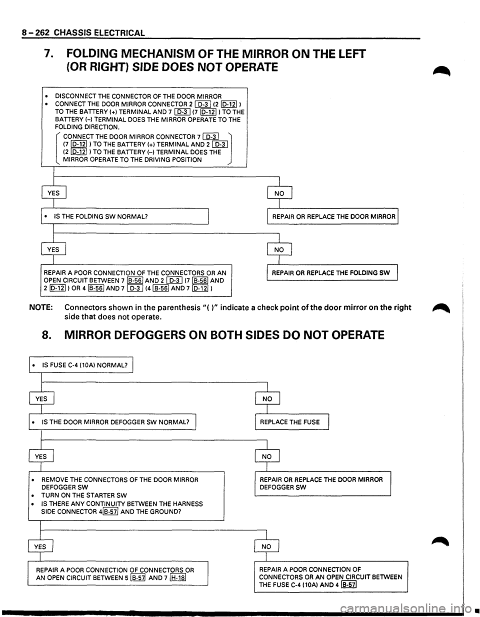
7. FOLDING MECHANISM OF THE MIRROR ON THE LEFT
(OR RIGHT) SIDE DOES NOT OPERATE
• DISCONNECT THE CONNECTOR OF THE DOOR MIRROR
• CONNECT THE DOOR MIRROR CONNECTOR 21 D-31 12ID-12I) TO THE BATTERY(+) TERMINAL AND 7 I D-3 I (7 ID-121) TO THE
BATTERY H TERMINAL DOES THE MIRROR OPERATE TO THE FOLDING DIRECTION.
[ CONNECT THE DOOR MIRROR CONNECTOR 7 co:3J ~ (7,D-121 ) TO THE BATTERY(+) TERMINAL AND 21 D-31 (2 D-12 ) TO THE BATTERY H TERMINAL DOES THE MIRROR OPERATE TO THE DRIVING POSITION
I
I
1
YES I I NO I
I I
• IS THE FOLDING SW NORMAL? I I REPAIR OR REPLACE
THE DOOR MIRROR I
I
I
1
YES I l NO I
I J
REPAIR A POOR CONNECTION OF THE CONNECTORS OR AN l REPAIR OR REPLACE THE FOLDING SW J OPEN CIRCUIT BETWEEN 7 IB-561 AND 2 I D-3 I !7IB-56I AND
2 ID-121) OR 4IB-56I AND 71 D-31 !4IB-56I AND 7ID-12I)
NOTE: Connectors shown in the parenthesis"()" indicate a check point of the door mirror on the right ~
side that does not operate.
8. MIRROR DEFOGGERS ON BOTH SIDES DO NOT OPERATE
• IS FUSE C-4 (10A) NORMAL? J
I
I I
YES
I NO I
I t
• IS THE DOOR MIRROR DEFOGGER sw NORMAL? I REPLACE THE FUSE I
I
l 1
YES I NO I
I I
• REMOVE THE CONNECTORS OF THE DOOR MIRROR REPAIR OR REPLACE THE DOOR MIRROR DEFOGGER SW DEFOGGER SW
• TURN ON THE STARTER SW
• IS THERE ANY CONTINUITY BETWEEN THE HARNESS
SIDE
CONNECTOR 4IB-57/ AND THE GROUND?
I
I
1
YES I NO I
I I
REPAIR A POOR CONNECTION OF CONNECTORS OR REPAIR A POOR CONNECTION OF
AN OPEN CIRCUIT BETWEEN siB-S~ AND 7IH-18I CONNECTORS OR AN OPEN CIRCUIT BETWEEN
THE
FUSE C-4 (10Al AND 4IB-57I
•
Page 1453 of 1928
CHASSIS ELECTRICAL 8-263
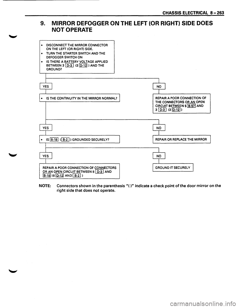
9. MIRROR DEFOGGER ON THE LEFT (OR RIGHT) SIDE DOES
NOT OPERATE
• DISCONNECT THE MIRROR CONNECTOR ON THE LEFT (OR RIGHT) SIDE.
• TURN THE STARTER SWITCH AND THE
DEFOGGER SWITCH ON
• IS THERE A BATTERY VOLTAGE APPLIED BETWEEN 31 D-31 13ID-12I I AND THE GROUND?
I
YES I NO I
l
• IS THE CONTINUITY IN THE MIRROR NORMAL? REPAIR A POOR CONNECTION OF
THE CONNECTORS OR AN OPEN
CIRCUIT BETWEEN sl B-571 AND
31 D-31 13ID-12I 1
I
YES I NO I
J
• IS I B-181 1(&[] I GROUNDED SECURELY? REPAIR OR REPLACE THE MIRROR
I
YES I NO I
I
REPAIR A POOR CONNECTION OF CONNECTORS GROUND IT SECURELY I
OR AN OPEN CIRCUIT BETWEEN al D-3 I AND
IB-1BI(aiD-12I AND~ 1
NOTE: Connectors shown in the parenthesis"()" indicate a check point of the door mirror on the
right side
that does not operate.
Page 1454 of 1928
8-264 CHASSIS ELECTRICAL
STARTER SWITCH
Refer to "START AND CHARGING" in this section.
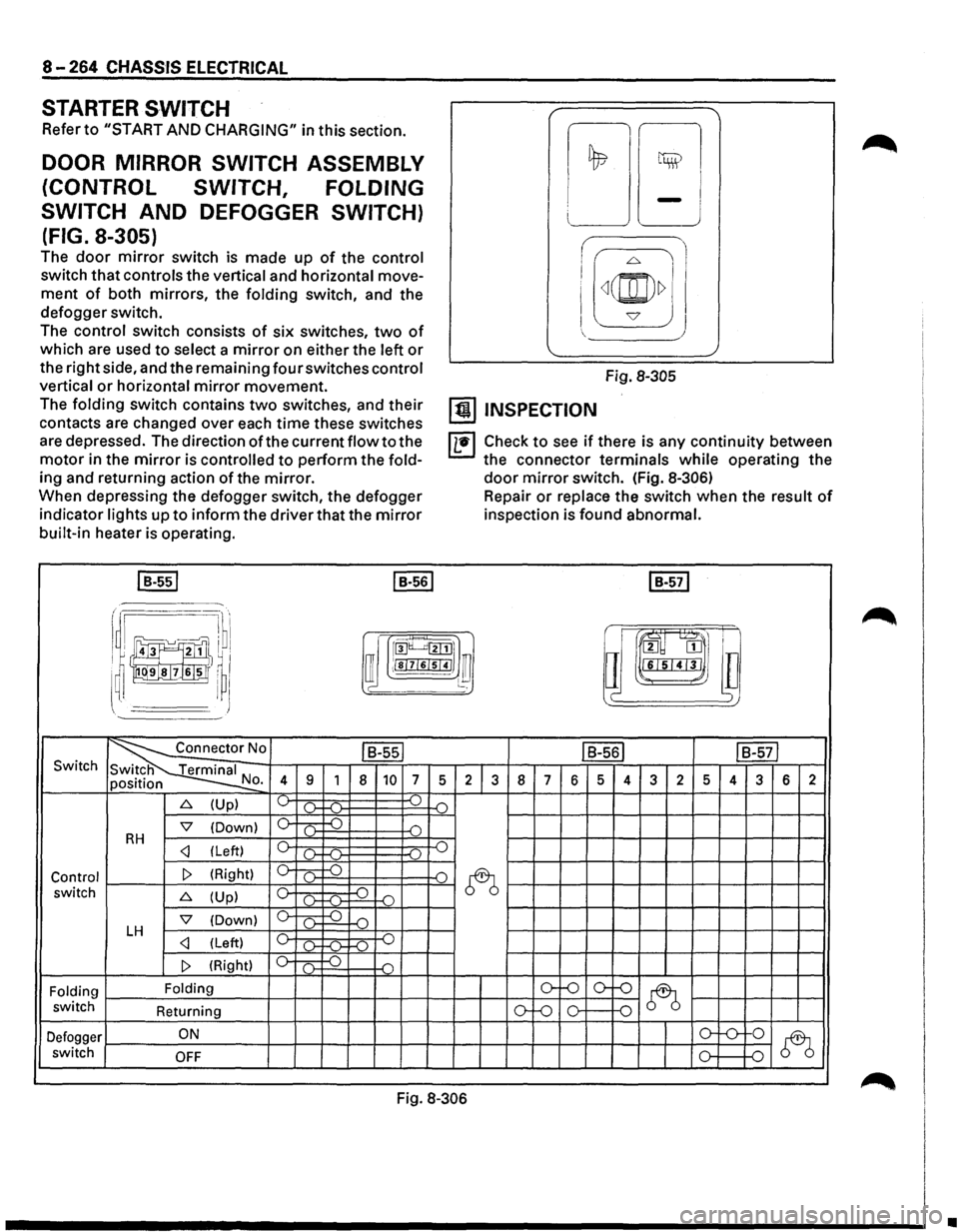
DOOR MIRROR SWITCH ASSEMBLY
(CONTROL SWITCH, FOLDING
SWITCH
AND DEFOGGER SWITCH)
(FIG. 8-305)
The door mirror switch is made up of the control
switch that controls the vertical and horizontal move
ment of both mirrors, the folding switch, and the
defogger switch.
The control switch consists of six switches, two of
which are used to select a mirror on either the left or
the right side, and the remaining four switches control
vertical or horizontal mirror movement.
The folding switch contains two switches, and their
contacts are changed over each time these switches
are depressed. The direction of the current flow to the
motor in the mirror is controlled to perform the fold
ing and returning action of the mirror.
When depressing the defogger switch, the defogger
indicator lights up to inform the driver that the mirror
built-in heater is operating.
I B-551 I B-561
i I I
!;l ~
LJ -J
I
I[~(@)~] J
Fig. 8-305
[!) INSPECTION
IL•I Check to see if there is any continuity between
the connector terminals while operating the
door mirror switch. (Fig. 8-306)
Repair or replace the switch when the result of
inspection is found abnormal.
I B-571
r .·~·· I ~ru·l
~~J!]}I ~ rroo~~l]
i !)~~1,1
a m
I ~ I ffi ;!sl7l6lsl41 ~ l~ lll"L•I'J'I•J ~~~
~' I J )
~0 ls-ssl IB-561 IB-571 Switch
N 4 9 1 8 10 7 5 2 3 8 7 6 5 4 3 2 5 4 3 6 2 o.
6. (Up) ~ ).. ...( ) .(")
'7 (Down) 0 c .) D RH c _.)
~ switch 6. (Up) c ~ -o ()-f-(l-
'7 (Down) 0 ( ) D LH c _.)
Folding Folding o-f-0 o--()
~ switch
Returning ()-Lo 0 0
Defogger ON o-'-0-
0
~ switch OFF 0 D
Fig. 8-306
•
Page 1455 of 1928
CHASSIS ELECTRICAL 8-265
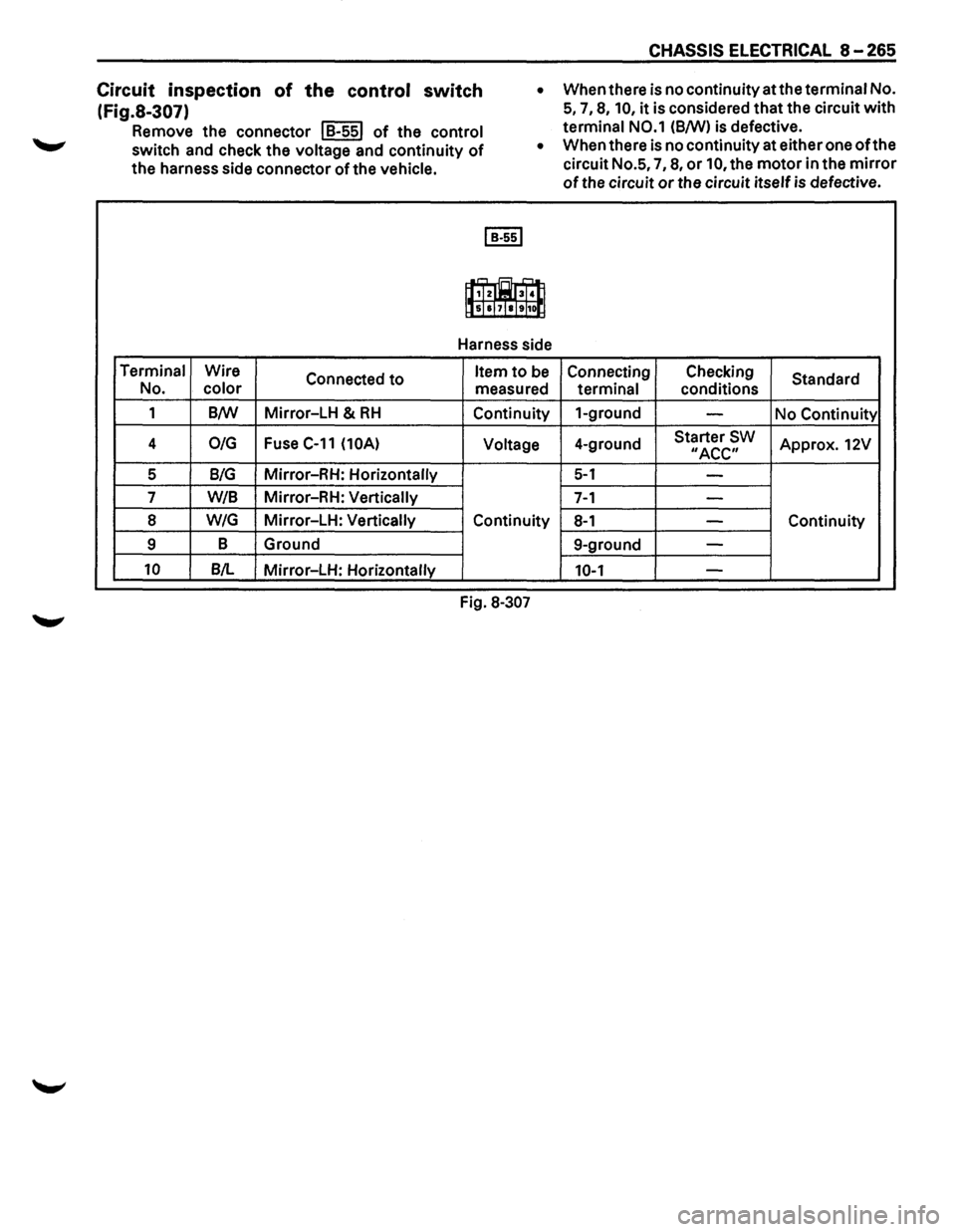
Circuit inspection of the control switch
(Fig.S-307)
Remove the connector I B-55l of the control
switch and check the voltage and continuity of
the harness side connector of the vehicle. •
When
there is no continuity at the terminal No.
5, 7, 8, 10, it is considered that the circuit with
terminal N0.1 (8/W) is defective.
Terminal Wire
Connected to No. color
1 B/W Mirror-LH & RH
4 0/G Fuse C-11 (10A)
5 B/G Mirror-RH: Horizontally
7
W/8 Mirror-RH: Vertically
8 W/G Mirror-LH: Vertically
9 B
Ground
10 B/L Mirror-LH: Horizontally •
When
there is no continuity at either one of the
circuit No.5,
7, 8, or 10, the motor in the mirror
of the circuit or the circuit itself is defective.
I B·55l
,...., = ....,,
1f,Tz003T•ll lls]sl7laltl1o[j
Harness side
Item to be Connecting Checking
Standard
measured
terminal conditions
Continuity 1-ground
-No
Continuity
Voltage 4-ground Starter SW Approx. 12V "ACC"
5-1 -
7-1 -
Continuity 8-1 -Continuity
9-ground
-
10-1 -
Fig. 8-307
Page 1456 of 1928
8-266 CHASSIS ELECTRICAL
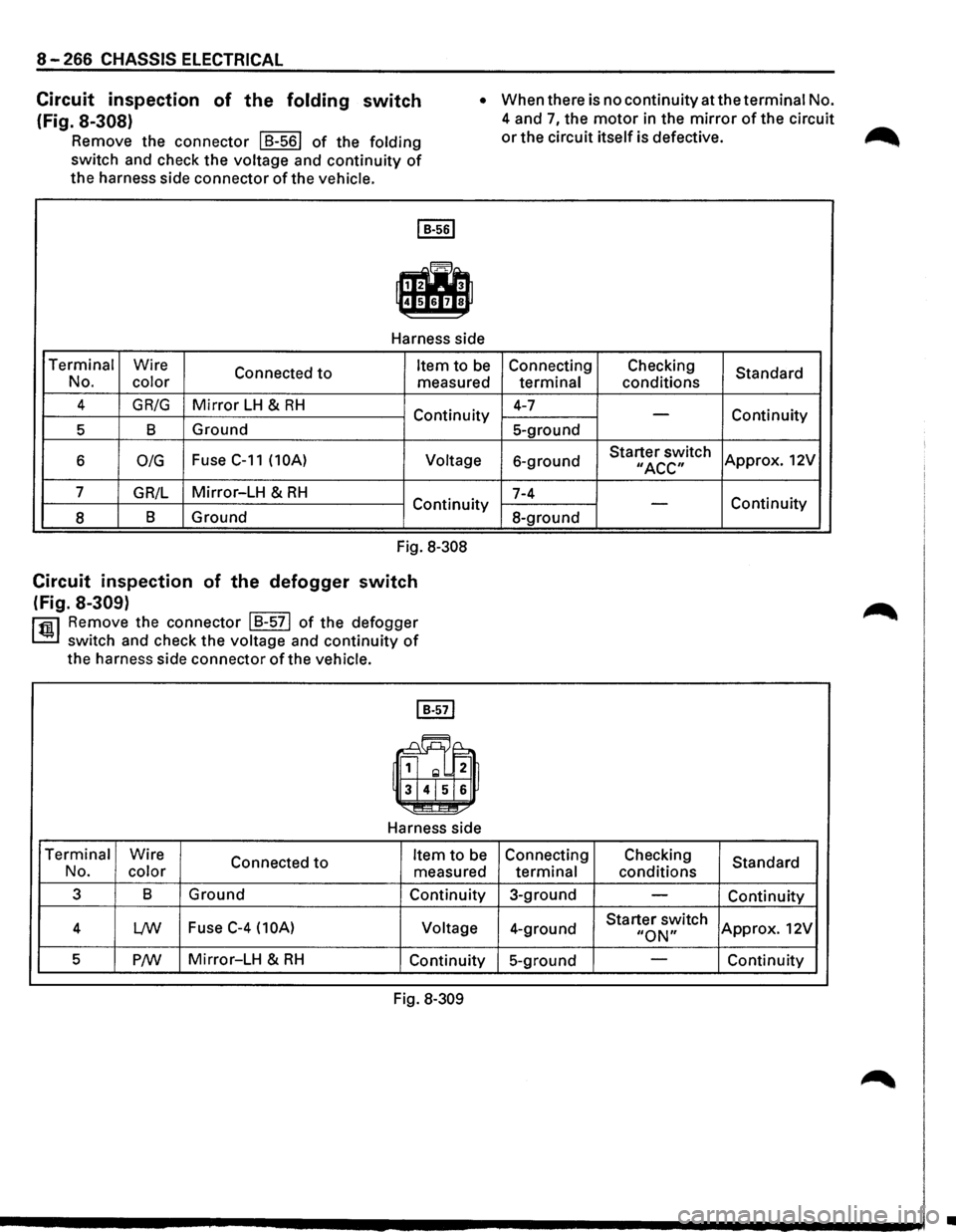
Circuit inspection of the folding switch
(Fig. 8-308)
Remove the connector I 8-561 of the folding
switch and check the voltage and
continuity of
the harness side connector of the vehicle.
• When there is no continuity at the terminal No.
4 and
7, the motor in the mirror of the circuit
or the circuit itself is defective.
I B·56l
f.lh
Harness side
Terminal Wire
Connected
to Item to be Connecting
No. color
measured terminal
4
GR/G Mirror LH & RH Continuity 4-7
5 8 Ground 5-ground
6
0/G Fuse C-11 (10A) Voltage
6-ground
7
GR/L Mirror-LH & RH 7-4
Continuity
8 8
Ground
8-ground
Fig. 8-308
Circuit inspection of the defogger switch
(Fig. 8-309)
rfiil Remove the connector I 8-571 of the defogger
~ switch and check the voltage and continuity of
the harness side connector ofthe vehicle.
Harness side
Terminal Wire
Connected
to No. color
Item to be Connecting
measured terminal
3 8
Ground
Continuity 3-ground
4
L/W Fuse C-4 (10A) Voltage
4-ground
5
P/W Mirror-LH & RH Continuity 5-ground
Fig. 8-309 Checking
conditions
-
Starter switch II ACC"
-
Checking
conditions
Starter switch
"ON"
Standard
Continuity
Approx. 12V
Continuity
Standard
Continuity
Approx. 12V
Continuity
•
Page 1457 of 1928
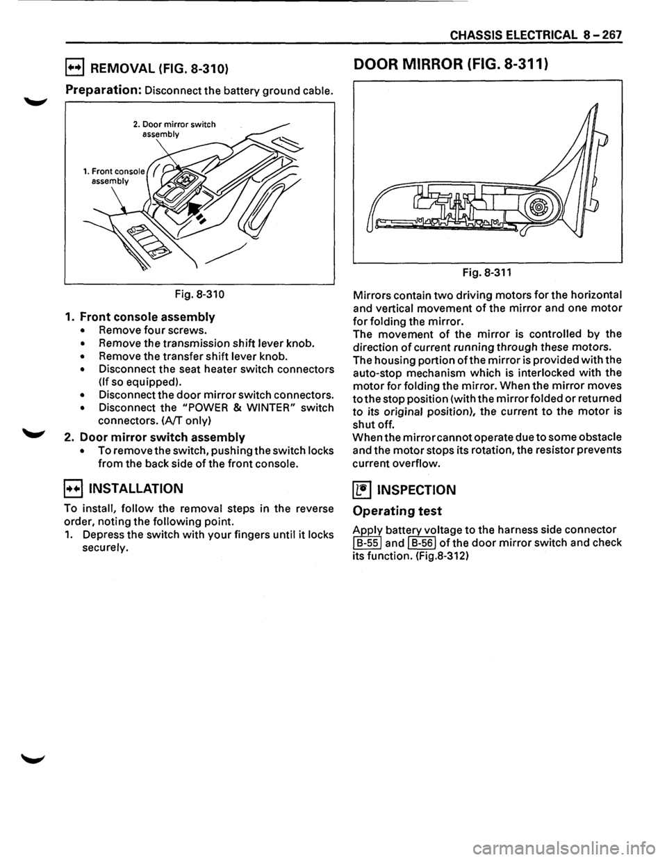
E) REMOVAL (FIG. 8-310)
Preparation: Disconnect the battery ground cable.
2. Door mirror switch assembly
Fig. 8-310
1. Front console assembly
• Remove four screws.
• Remove the transmission shift lever knob.
• Remove the transfer shift lever knob.
• Disconnect the seat heater switch connectors
(If so equipped).
• Disconnect the door mirror switch connectors.
• Disconnect the "POWER & WINTER" switch
connectors.
(A/T only)
2. Door mirror switch assembly
• To remove the switch, pushing the switch locks
from the back side of the front console.
B INSTALLATION
To install, follow the removal steps in the reverse
order, noting the
following point.
1. Depress the switch with your fingers until it locks
securely.
CHASSIS ELECTRICAL 8-267
DOOR MIRROR (FIG. 8-311)
Fig. 8-311
Mirrors contain two driving motors for the horizontal
and vertical movement of the mirror and one motor
for folding the mirror.
The movement of the mirror is controlled by the
direction
of current running through these motors.
The housing portion
ofthe mirror is provided with the
auto-stop mechanism which is
interlocked with the
motor for folding the mirror. When the mirror moves
to the stop position (with the mirror folded or returned
to its original position), the current to the motor is
shut off.
When the
mirror cannot operate due to some obstacle
and the motor stops its rotation, the resistor prevents
current
overflow.
~ INSPECTION
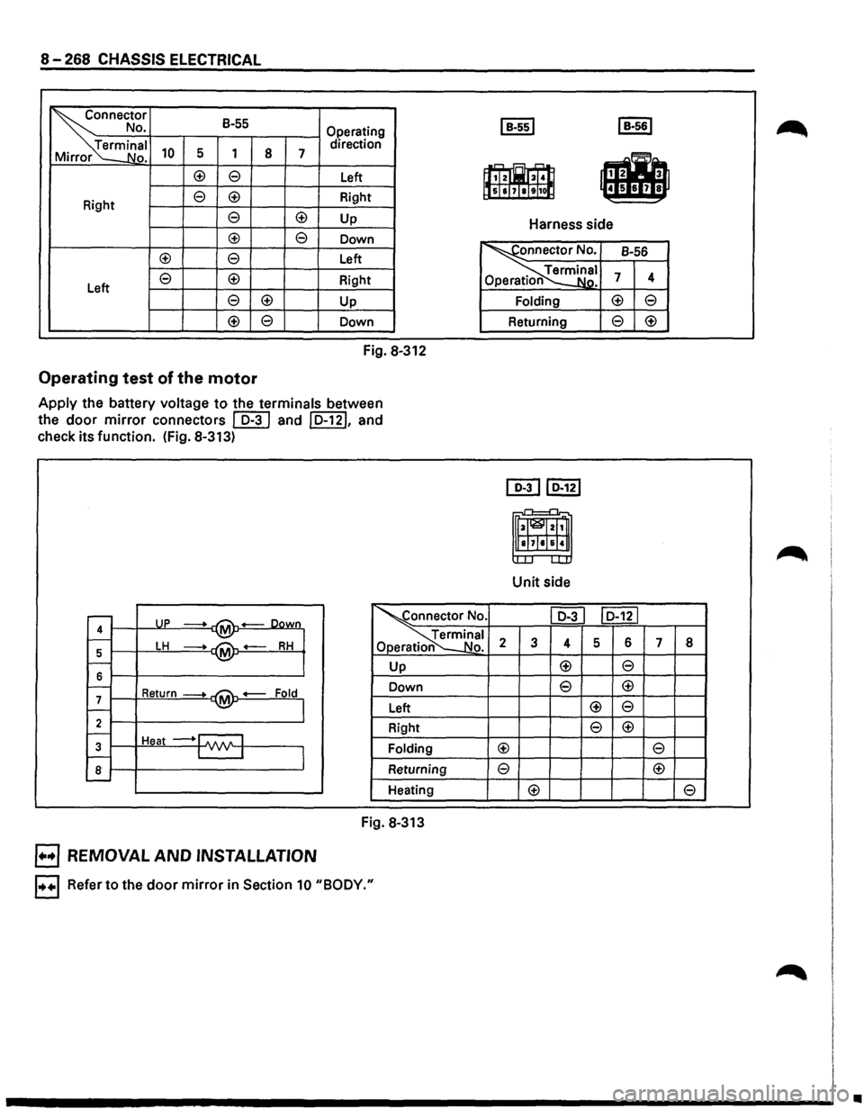
Operating test
Apply battery voltage to the harness side connector
I B-ssl and I B-561 of the door mirror switch and check
its function. (Fig.8-312)
Page 1458 of 1928
8-268 CHASSIS ELECTRICAL
l~t'
B-55 No.
Operating
ina
I 10 5 1 8 direction
Ho. 7
c±l e Left
e c±l Right
Right
e c±l Up
c±l e Down
c±l e Left
Left
e c±l Right
e c±l Up
<±> e Down
Fig. 8-312
Operating test of the motor
Apply the battery voltage to the terminals between
the
door mirror connectors ~ and ID-121, and
check its function. (Fig. 8-313)
I B-ssl I B-561
•
• ,...., s.:::L -=--
~it! I]&ISI7111t11ol:l 8
Harness side
~nnector No. B-56
~erminal Ope rat o Nn. 7 4
Folding <±> e
Returning e <±>
~ ID-121
_.....,_ .r-1
m 4
~ L..U.
Unit side
......--UP -oown ~onnector No . I D-31 I D-121
--M 4 ~~nal 1--LH RH Opera .,No. 2 3 4 5 6 7 5 --M -1---Up <±> e 6 e <±> -Return--Fold Down 7 M --I Left <±> e
2 Right e <±> -Heat --1 .AAA I 3 I v v I Folding c±l e -8 Returning e c±l L...-Heating <±>
Fig. 8-313
EJ REMOVAl AND INSTAllATION
1++1 Refer to the door mirror in Section 10 "BODY."
8
e
•
Page 1459 of 1928
CHASSIS ELECTRICAL 8-269
MEMO
~)
Page 1460 of 1928
8-270 CHASSIS ELECTRICAL
ANTI-THEFT SYSTEM
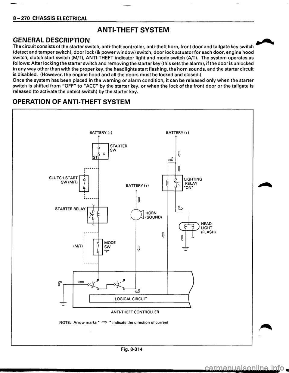
GENERAL DESCRIPTION .......
The circuit consists ofthe starter switch, anti-theft controller, anti-theft horn, front door and tailgate key switch
(detect and tamper switch),
door lock (&power window) switch, door lock actuator for each door, engine hood
switch, clutch start switch (MfT),
ANTI-THEFT indicator light and mode switch (AfT). The system operates as
follows: After locking the starter switch and removing the starter key (this sets the alarm),
ifthe door is unlocked
in any
way other than with the proper key, the headlights start flashing, the horn sounds, and the starter circuit
is disabled. (However,
the engine hood and all the doors must be locked and closed.)
Once the system has been placed in the warning or alarm condition, it can be released only when the starter
switch is shifted
from "OFF" to "ACC" by the starter key, or when the lock of the front door or the tailgate is
released (to activate the detect switch)
by the starter key.
OPERATION OF ANTI-THEFT SYSTEM
'
'
CLUTCH START m
SW(M/Tiw
' '
'
BATIERY(+)
0 ST
STARTER sw
BATIERY(+)
L------
STARTER RELAY
' ' (MIT):
'
'
'
HORN
(SOUND)
ANTI-THEFT CONTROLLER
BATIERY(+)
LIGHTING
RELAY
"ON"
HEADLIGHT (FLASH)
NOTE: Arrow marks u ~ u indicate the direction of current
Fig. 8-314
•