ISUZU TROOPER 1995 Workshop Manual
Manufacturer: ISUZU, Model Year: 1995, Model line: TROOPER, Model: ISUZU TROOPER 1995Pages: 1928
Page 1421 of 1928
WIPER BLADE RUBBER
B REMOVAL
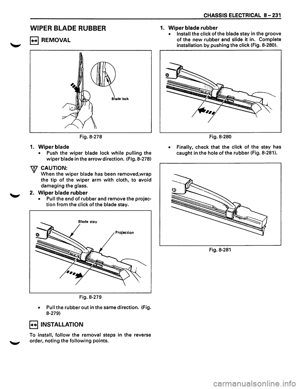
Fig. 8-278
1. Wiper blade
• Push the wiper blade lock while pulling the
wiper blade in the arrow direction. (Fig. 8-278)
W CAUTION:
When the wiper blade has been removed,wrap
the
tip of the wiper arm with cloth, to avoid
damaging the
glass.
2. Wiper blade rubber
• Pull the end of rubber and remove the projec
tion from the click of the blade stay.
Blade stay
Projection
Fig. 8-279
• Pull the rubber out in the same direction. (Fig.
8-279)
B INSTALLATION
To install, follow the removal steps in the reverse
'--"' order, noting the following points.
CHASSIS ELECTRICAL 8-231
1. Wiper blade rubber
• Install the click of the blade stay in the groove
of the new rubber and slide it in. Complete
installation by pushing the click (Fig. 8-280).
Fig. 8-280
• Finally,
check that the click of the stay has
caught in the
hole of the rubber (Fig. 8-281 ).
Fig. 8-281
Page 1422 of 1928
8 -232 CHASSIS ELECTRICAL
HEADLIGHT WIPER/WASHER
GENERAL DESCRIPTION
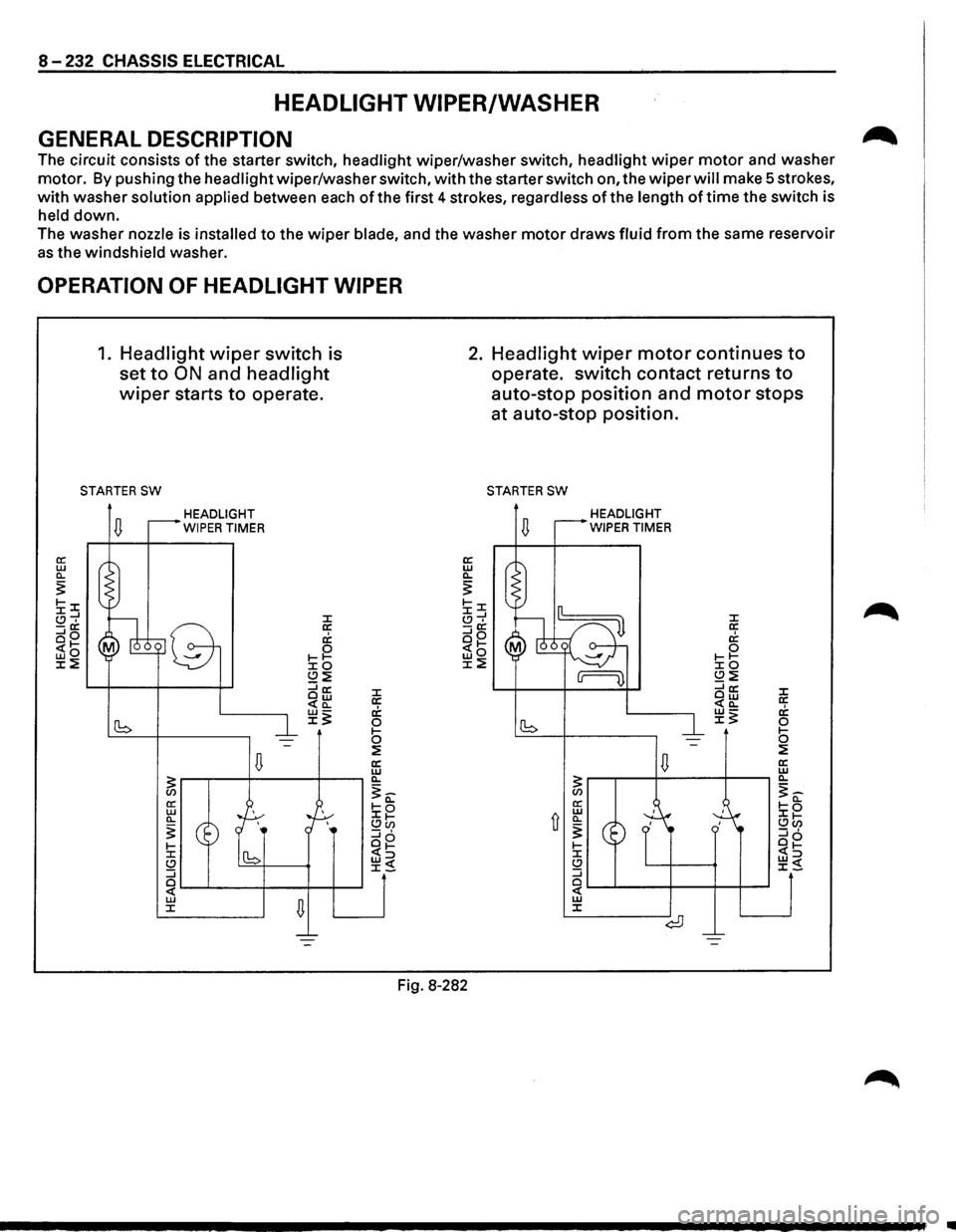
The circuit consists of the starter switch, headlight wiper/washer switch, headlight wiper motor and washer
motor. By pushing the headlight wiper/washer switch, with the starter switch on, the wiper will make 5 strokes,
with washer solution applied between each of the first 4 strokes, regardless of the length of time the switch is
held down.
The washer nozzle is installed to the wiper blade, and the washer motor draws fluid from the same reservoir
as the windshield washer.
OPERATION OF HEADLIGHT WIPER
1. Headlight wiper switch is
set
to ON and headlight
wiper starts to operate.
STARTER SW
HEADLIGHT
WIPER TIMER
J: a: c1; 0 1-1-J:O (.!)~ ::::ia: Ow <(a_
~~
Fig. 8-282
2. Headlight wiper motor continues to
operate. switch contact returns to
auto-stop position and motor stops
at auto-stop position.
STARTER SW
HEADLIGHT
WIPER TIMER
..
Page 1423 of 1928
::!!
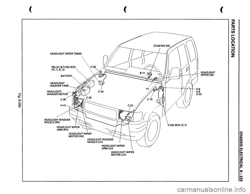
HEADLIGHT
WIPER
TIMER
'
RELAY
& FUSE
BOX
C-39
(fl-1,FL-21
~
BATTERY
HEADLIGHT WASHER
TANK
HEADLIGHT, WASHER
MOTOR
HEADLIGHT
WASHER
NOZZLE(RHI
(
HEADLIGHT
WIPER
MOTORILHI
~II
1/
//'
I
H-8
HEADLIGHT WIPERSW.
H-9 H-25
(
;g ~ r-0 n ~ 0 2
0 X )> en
en Cii m rm ~ :D 0 ~ 00 I N w
w
Page 1424 of 1928
8-234 CHASSIS ELECTRICAL
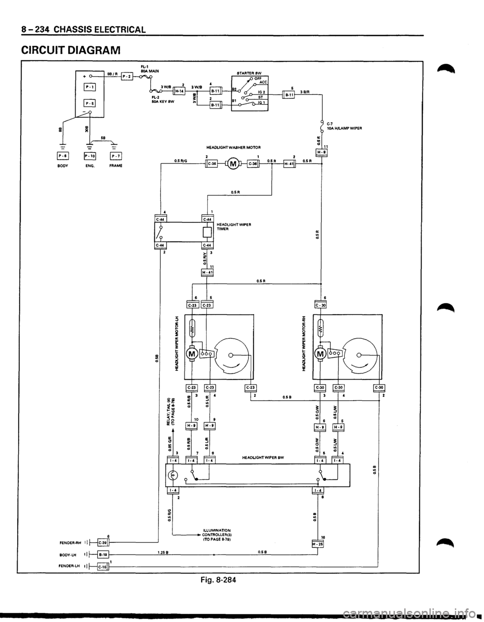
CIRCUIT DIAGRAM
3 B/R
C-7 lOA H/I.AMP WIPER
HEADLIGHT WASHER
MOTOR
B 0.5 RiG BODY ENG. FRAME
0.5R
0.5 R
0.5 B
HEADLIGHT WIPER SW
" 0! ID .. .. 0 0
ILLUMINATION CONTROLLER(31 16 (TO PAGE B-781 FENOER..RH II H-25
II 1.258 0.68 BODY-LH
FENOER-LH II
Fig.
8-284
Ill
Page 1425 of 1928
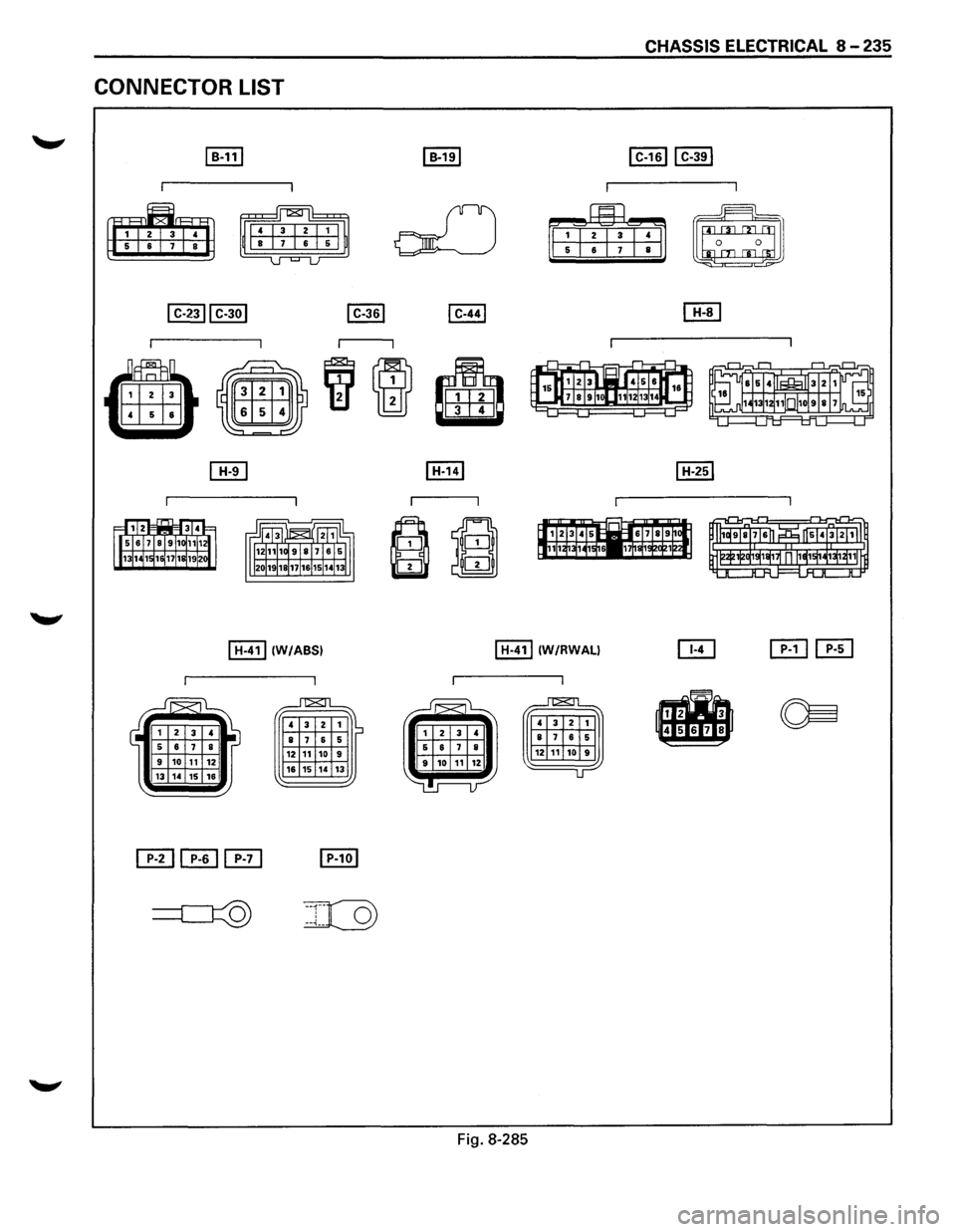
CONNECTOR LIST
~
~
I H-411 (W/ABSI
~
4 3 2
8 7 6 1 5 12 11 10 9 16 15
14 13
I H-411 (W/RWALI
b
Fig. 8-285
CHASSIS ELECTRICAL 8 -235
~
~
Page 1426 of 1928
8-236 CHASSIS ELECTRICAL
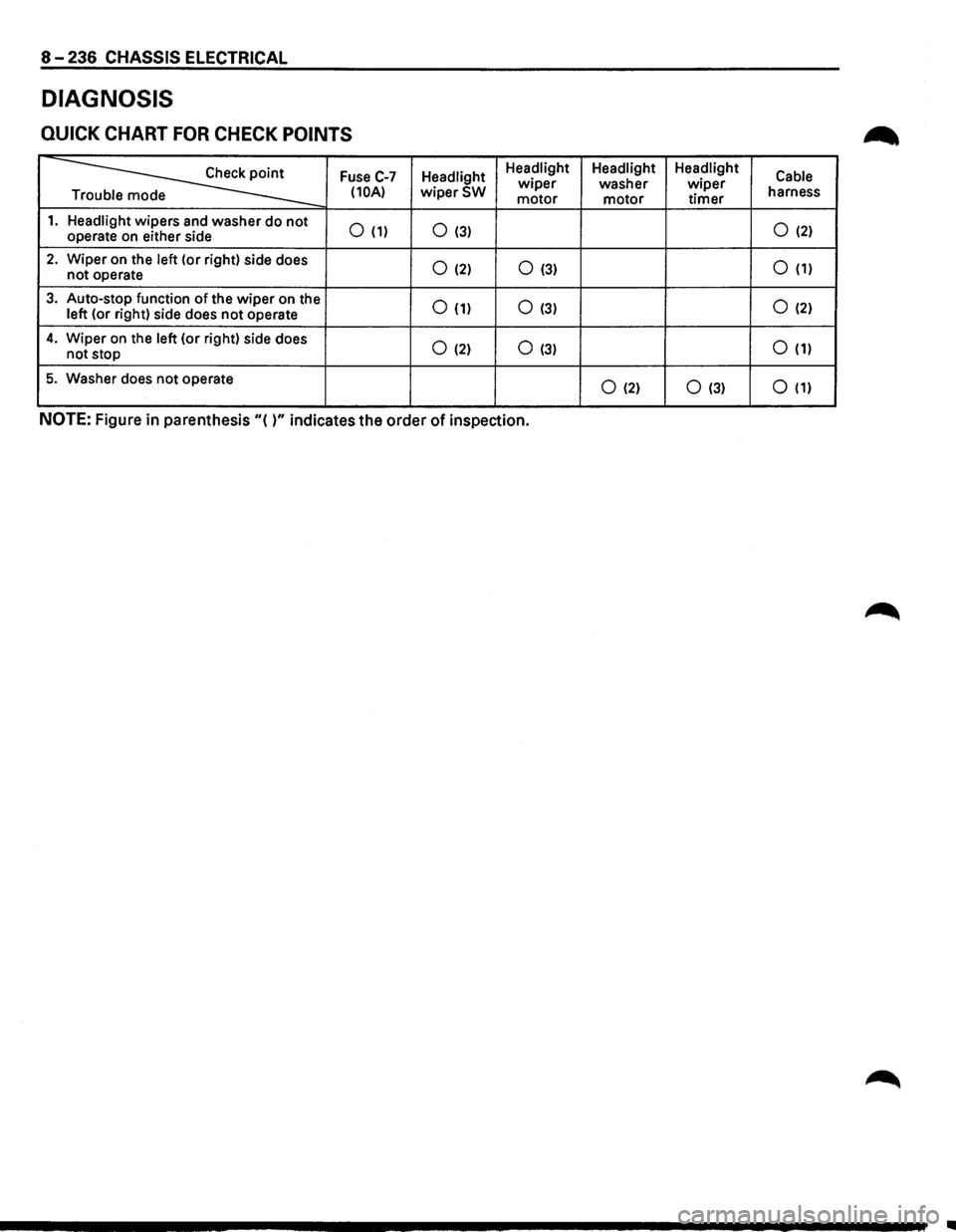
DIAGNOSIS
QUICK CHART FOR CHECK POINTS
~
Fuse C-7 Headlight Headlight
Headlight Headlight
Cable wiper washer wiper (10A) wiperSW motor motor timer harness
e
1. Headlight wipers and washer do not 0 (1) 0 (3) 0 (2) operate on either side
2. Wiper on the left (or right) side does 0 (2) 0 (3) 0 (1) not operate
3. Auto-stop function of the wiper on the 0 (1) 0 (3) 0 (2) left (or right) side does not operate
4. Wiper on the left (or right) side does 0 (2) 0 (3) 0 (1) not stop
5. Washer does not operate 0 (2) 0 (3) 0 (1)
NOTE: Figure in parenthesis "( )" indicates the order of inspection.
Page 1427 of 1928
CHASSIS ELECTRICAL 8-237
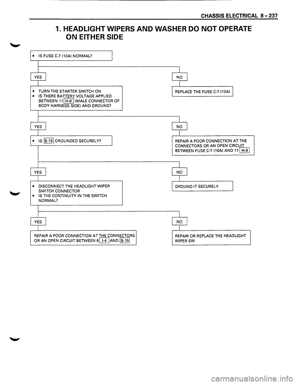
1. HEADLIGHT WIPERS AND WASHER DO NOT OPERATE
ON EITHER SIDE
• IS FUSE C-7 (10A) NORMAL? I
I
YES
I NO I
I
• TURN THE STARTER SWITCH ON REPLACE THE FUSE C-7 (10A) I
• IS THERE BATTERY VOLTAGE APPLIED
BETWEEN 111 H-8 I (MALE CONNECTOR OF BODY HARNESS SIDE) AND GROUND?
I
YES I NO I
I
• IS IB-19IGROUNDED SECURELY? I REPAIR A POOR CONNECTION AT THE CONNECTORS OR AN OPEN CIRCUIT BETWEEN FUSE C-7 (10A) AND 111 H-81
I
YES
I NO I
I
• DISCONNECT THE HEADLIGHT WIPER
GROUND IT SECURELY J SWITCH CONNECTOR
• IS THE CONTINUITY IN THE SWITCH
NORMAL?
I
YES I NO
I
REPAIR A POOR CONNECTION AT THE CONNECTORS
REPAIR OR REPLACE THE HEADLIGHT OR AN OPEN CIRCUIT BETWEEN 6(}DAND IB-191 WIPER SW
Page 1428 of 1928
8-238 CHASSIS ELECTRICAL
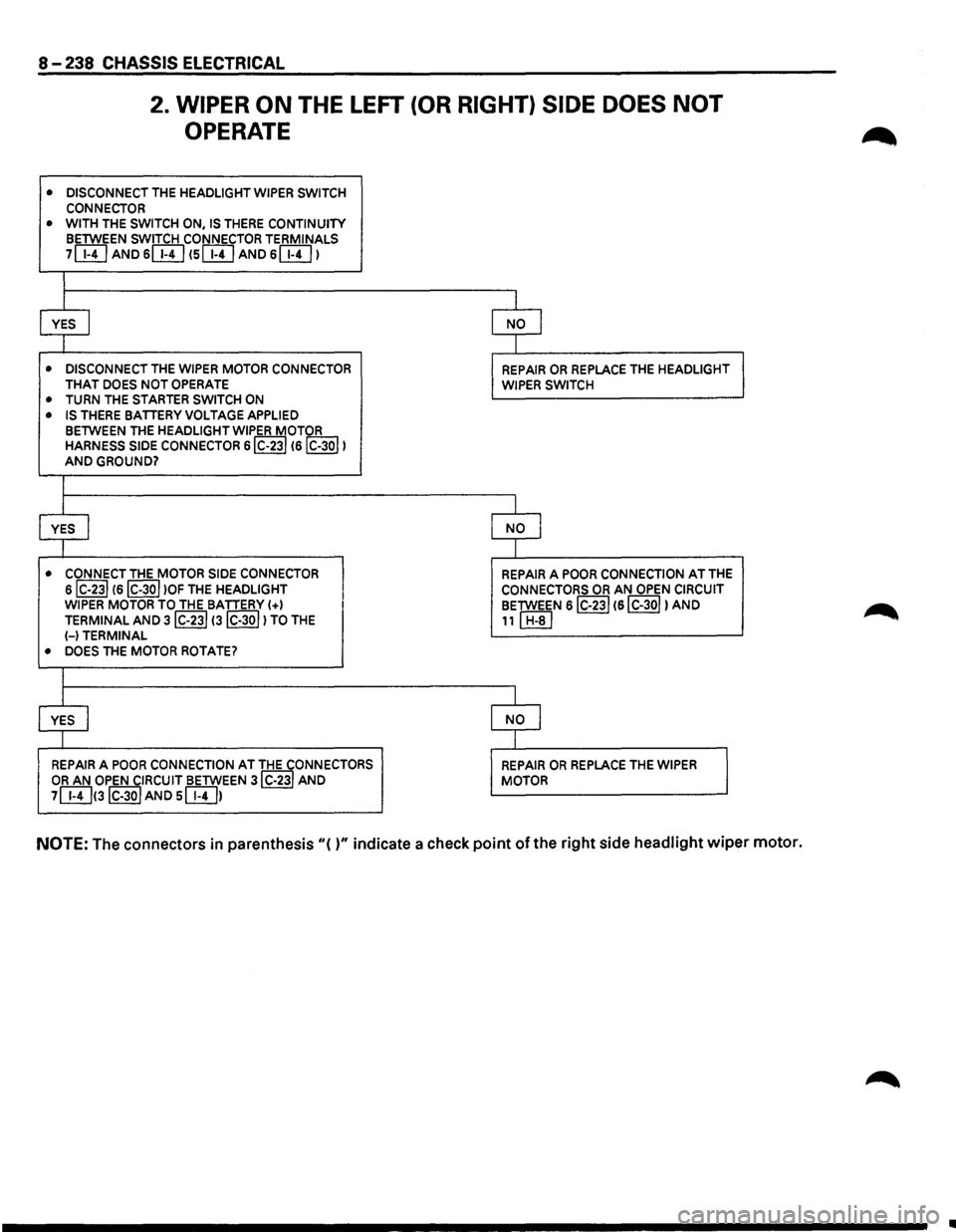
2. WIPER ON THE LEFT (OR RIGHT) SIDE DOES NOT
OPERATE
• DISCONNECT THE HEADLIGHT WIPER SWITCH
CONNECTOR • WITH THE SWITCH ON, IS THERE CONTINUITY BETWEEN SWITCH CONNECTOR TERMINALS
7[}!] AND 6[}!] (SIT!] AND s[}!J I
I
I
I
YES I NO I
l I
• DISCONNECT THE WIPER MOTOR CONNECTOR REPAIR OR REPLACE THE HEADLIGHT THAT DOES NOT OPERATE WIPER SWITCH • TURN THE STARTER SWITCH ON
• IS THERE BATIERY VOLTAGE APPLIED
BETWEEN THE HEADLIGHT WIPER MOTOR HARNESS SIDE CONNECTOR s!C-231
I I
YES I NO I
I I
• CONNECT THE MOTOR SIDE CONNECTOR
I
REPAIR A POOR CONNECTION AT THE
siC-231
I
I I
YES I NO I
I I
REPAIR A POOR CONNECTION AT THE CONNECTORS REPAIR OR REPLACE THE WIPER OR AN OPEN CIRCUIT BETWEEN 3IC-23I AND MOTOR
7[}!]<3IC-30I AND s[}!J1
NOTE: The
connectors in parenthesis "( )" indicate a check point of the right side headlight wiper motor.
•
Page 1429 of 1928
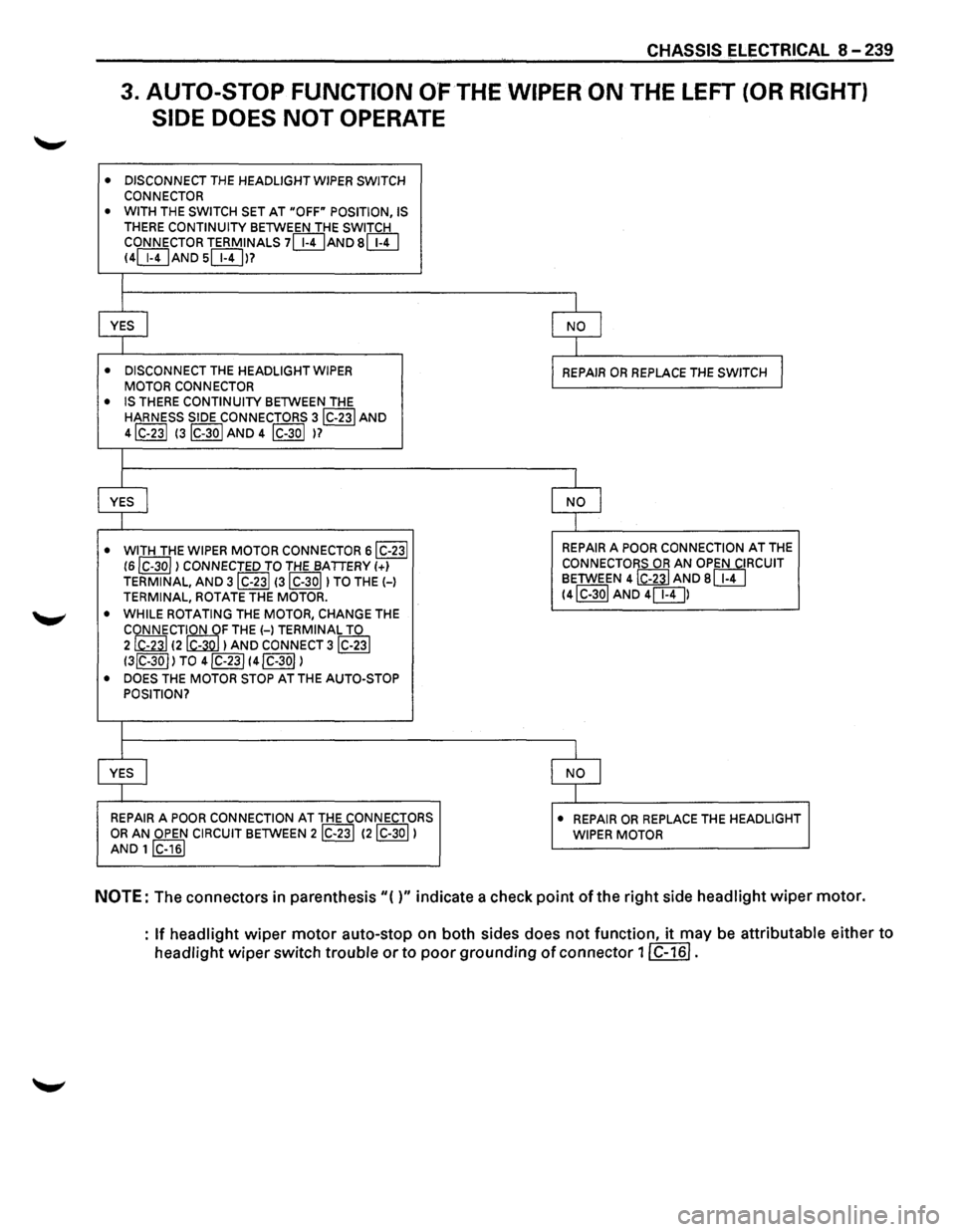
CHASSIS ELECTRICAL 8-239
3. AUTO-STOP FUNCTION O'FTHE WIPER ON THE LEFT (OR RIGHT)
SIDE DOES
NOT OPERATE
• DISCONNECT THE HEADLIGHT WIPER SWITCH
CONNECTOR
• WITH THE SWITCH SET AT "OFF" POSITION, IS
THERE CONTINUITY BETWEEN THE SWITCH
CONNECTOR TERMINALS 7[WAND s[}!] 14[WAND s[Wl?
I
I I
YES j NO I
I
I
• DISCONNECT THE HEADLIGHT WIPER REPAIR OR REPLACE THE SWITCH I MOTOR CONNECTOR
• IS THERE CONTINUITY BETWEEN THE
HARNESS SIDE CONNECTORS 3IC-23I AND
4IC-23I 13lc-3o I AND 4 lc-3ol )?
I
I I
YES
I NO
I I
• WITH
THE WIPER MOTOR CONNECTOR 6IC-23I REPAIR A POOR CONNECTION AT THE
16IC-3ol) CONNECTED TO THE BATTERY 1+1 CONNECTORS OR AN OPEN CIRCUIT
TERMINAL,
AND 3IC-23I 13IC-30I) TO THE H BETWEEN 4 ~AND 8 [}!]
TERMINAL, ROTATE THE MOTOR. 14IC-30I AND 4[8])
•
WHILE ROTATING THE MOTOR, CHANGE THE
CONNECTION OF THE H TERMINAL TO 2@ 12 6Q}) AND CONNECT 3lC-23I
13lC-30I) TO 4lC-23I 14lC-30I)
• DOES THE MOTOR STOP AT THE AUTO-STOP
POSITION?
I
I I
YES
I NO I
I I
REPAIR A POOR CONNECTION AT THE CONNECTORS • REPAIR OR REPLACE THE HEADLIGHT OR AN OPEN CIRCUIT BETWEEN 2IC-23l 12lC-30l) WIPER MOTOR AND 1 IC-161
NOTE: The connectors in parenthesis"{)" indicate a check point ofthe right side headlight wiper motor.
:
If headlight wiper motor auto-stop on both sides does not function, it may be attributable either to
headlight wiper switch trouble or to poor grounding of connector 11 C-161.
Page 1430 of 1928
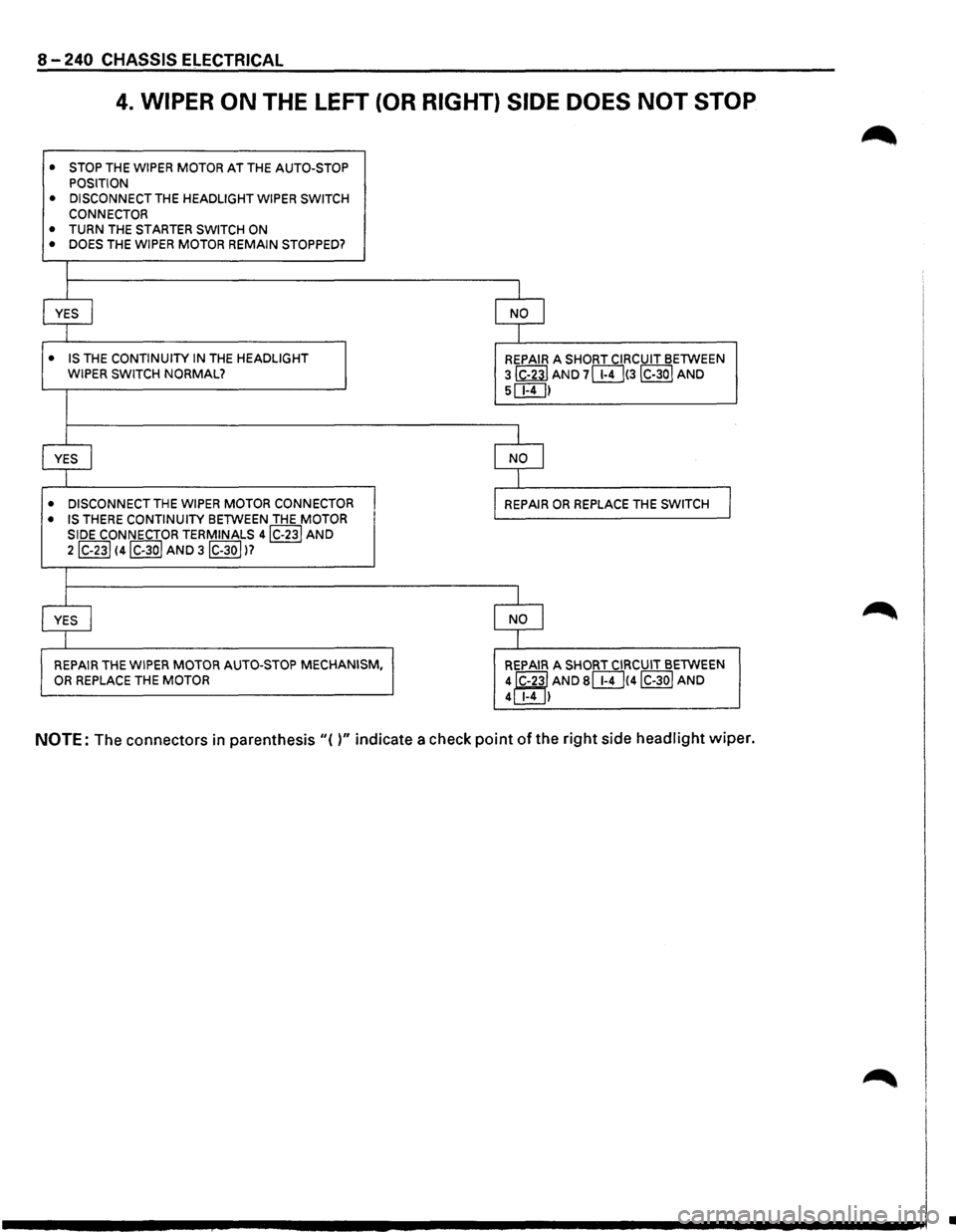
8-240 CHASSIS ELECTRICAL
4. WIPER ON THE LEFT (OR RIGHT) SIDE DOES NOT STOP
•
STOP THE WIPER MOTOR AT THE AUTO-STOP
POSITION
• DISCONNECT THE HEADLIGHT WIPER SWITCH
CONNECTOR
• TURN THE STARTER SWITCH ON
• DOES THE WIPER MOTOR REMAIN STOPPED?
I
YES
I NO I
I
• IS THE CONTINUITY IN THE HEADLIGHT
REPAIR A SHORT CIRCUIT BETWEEN WIPER SWITCH NORMAL? 3 ~AND 7lli]!3IC-30I AND
5c:E!]I
I
YES I NO I
I
• DISCONNECT THE WIPER MOTOR CONNECTOR
REPAIR OR REPLACE THE SWITCH I • IS THERE CONTINUITY BETWEEN THE MOTOR
SIDE CONNECTOR TERMINALS 4IC-23J AND
2lc-23l 14IC-3ol AND 3IC-30JI?
I
YES I NO I
I
REPAIR
THE WIPER MOTOR AUTO-STOP MECHANISM,
REPAIR A SHORT CIRCUIT BETWEEN OR REPLACE THE MOTOR
4J'C-23l AND slli]!4JC-30J AND 4 1-4 I
NOTE: The connectors in parenthesis "( )" indicate a check point of the right side headlight wiper.
•