ISUZU TROOPER 1995 Workshop Manual
TROOPER 1995
ISUZU
ISUZU
https://www.carmanualsonline.info/img/61/57183/w960_57183-0.png
ISUZU TROOPER 1995 Workshop Manual
Page 1571 of 1928
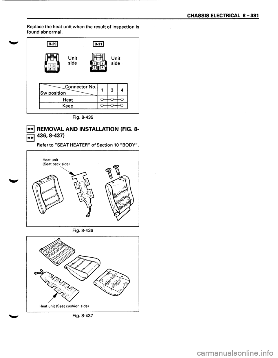
Replace the heat unit when the result of inspection is
found abnormal.
~
•
Unit
side
~· Sw
Heat
Keep
Fig. 8-435
1
,.....
o-
Unit
side
3
,.....
4
,.....
---o--o
B REMOVAL AND INSTALLATION (FIG. 8-
B 436, 8-437)
Referto "SEAT HEATER" of Section 10 "BODY".
Heat unit
!Seat back side)
Fig. 8-436
Heat unit (Seat cushion side)
Fig. 8-437
CHASSIS ELECTRICAL 8-381
Page 1572 of 1928
8-382 CHASSIS ELECTRICAL
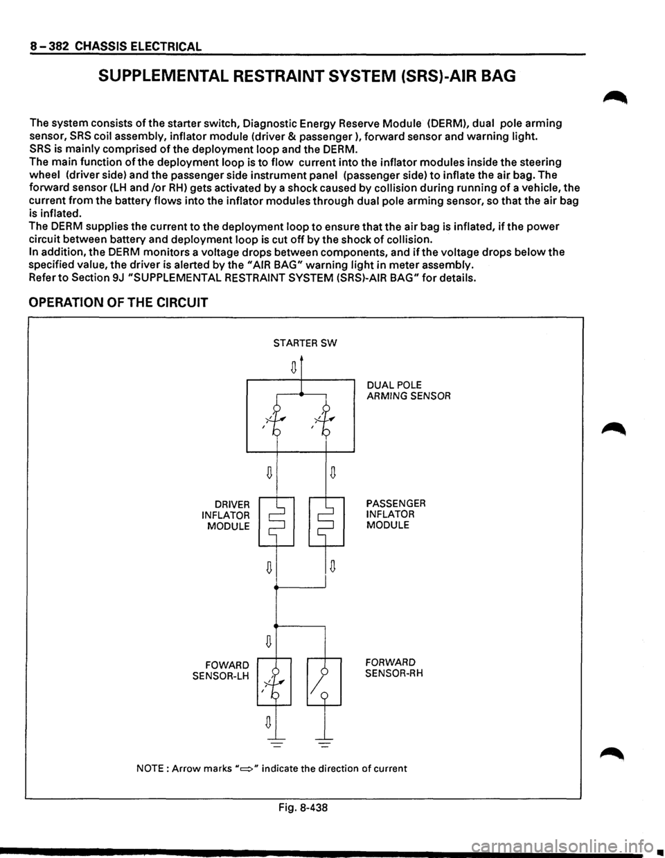
SUPPLEMENTAL RESTRAINT SYSTEM (SRS)-AIR BAG
The system consists of the starter switch, Diagnostic Energy Reserve Module (OERM), dual pole arming
sensor,
SRS coil assembly, inflator module (driver & passenger), forward sensor and warning light.
SRS is mainly comprised of the deployment loop and the DERM.
The main function of the deployment loop is to flow current into the inflator modules inside the steering
wheel (driver side) and the passenger side instrument panel (passenger side) to inflate the air bag. The
forward sensor
(LH and /or RH) gets activated by a shock caused by collision during running of a vehicle, the
current
from the battery flows into the inflator modules through dual pole arming sensor, so that the air bag
is
inflated.
The DERM supplies the current to the deployment loop to ensure that the air bag is inflated, if the power
circuit between battery and deployment loop is cut off by the shock of collision.
In
addition, the DERM monitors a voltage drops between components, and if the voltage drops below the
specified
value, the driver is alerted by the "AIR BAG" warning light in meter assembly.
Refer to Section 9J "SUPPLEMENTAL RESTRAINT SYSTEM (SRS)-AIR BAG" for details.
OPERATION OF THE CIRCUIT
DRIVER
INFLATOR MODULE
FOWARD
SENSOR-LH
D
D
STARTER SW
D
1
DUAL POLE ARMING SENSOR
PASSENGER
INFLATOR
MODULE
FORWARD
SENSOR-RH
NOTE: Arrow marks "c::::>" indicate the direction of current
Fig. 8-438
•
Page 1573 of 1928
(
PASSENGER
INFLATOR
MODULE
H-14
RELAY
& FUSE
BOX
H-50
(Fl-l,FL-21
"T1 ce·
BATTERY
00 I .J>. ~
C-49
FORWARD
SENSOR
(RHI
FORWARD
SENSOR
(LHI
(
(
SRS
COIL
ASSEMBLY
DRIVER
INFLATOR
MODULE
FUSE
BOX
(C-1,C-21,C-22,C-23,C-241
C-48
CONDENSOR
!NCI
;g ~ r-0 0 ~ -0 2
0 ::t ):lo en
en c;; m rm 0 -t :a ~ r-eo I w co w
Page 1574 of 1928
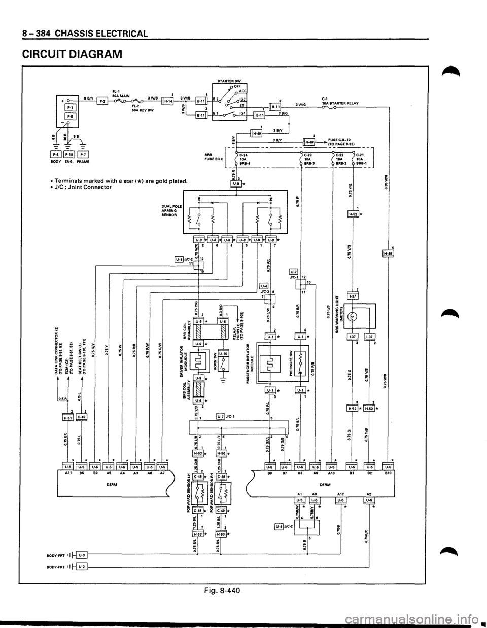
8-384 CHASSIS ELECTRICAL
CIRCUIT DIAGRAM
BODY ENG. FRAME
• Terminals marked with a star(*) are gold plated.
• J/C ; Joint Connector
fi "' 6 ;:-~ ~t; ~ >-t;: ~g " "' u"' ::: .. -~ 0 ,. .. ~: zw _w
"" 0" w., .. t. i:: =:: !(o frl@. ~g cl;
0.15R
~ ~ :e 0
0 ~
~
DUAL POLE ARMING SENSOR
~ " ~
@2)JtC·1
~J/C-2
3W/G
.. "' 0
ID "' 0
C-1 10A STARTER RELAY
BODY-FRT ~~~----------------------------------~~----~----------------------------~--------~
BODY-FRT 11~------------------------------------------------------------------------------------------__J
Fig. 8-440
H-..
•
Page 1575 of 1928
CHASSIS ELECTRICAL 8-385
CONNECTOR LIST
~ I C-4sll C-491 I H-141
elm 8
•
~ ~ 2 i
I H-491 I H-50 II H-531 I H-511
db SJ ~ m ~ ~
IH-521~ [ill] [IT] [ill @][IT]
ITI]@I]
•
~·t~ A ~ ~
I P-10 I ~ [ll]
ILQ) -
•
~ m C!HIJ m hi
~ [E]
=t,--, ,-··:l ... ____ ::: ___ _J
Fig. 8-441
Page 1576 of 1928
Page 1577 of 1928
RADIO 9A-1
ACCESSORIES
Radio .................................................. .
Parts Location ..............................•...........
Circuit Diagram ......•.................................
Antenna ....•......................................•........
Auto Antenna ......................................... .
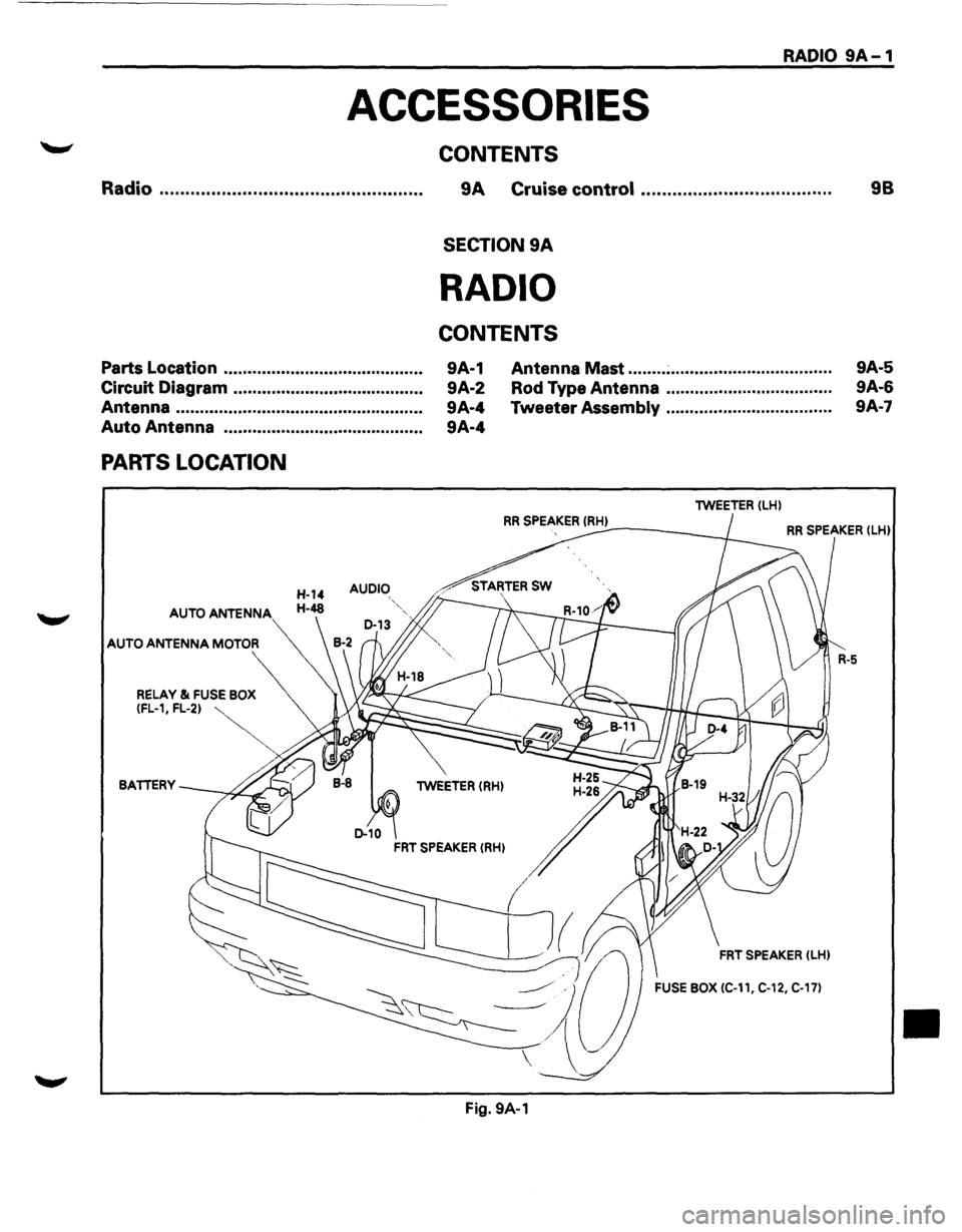
PARTS LOCATION
AUDIO
AUTO ANTENNA
AUTO ANTENNA MOTOR
CONTENTS
9A Cruise control ................................... ..
SECTION 9A
RADIO
CONTENTS
9A-1
9A-2
9A-4
9A-4 Antenna
Mast ........ ~ ................................. .
Rod Type Antenna .................................. .
Tweeter
Assembly .................................. .
lWEETER (LH)
98
9A-5
9A-6
9A·7
RR SPEAKER !RH) ----~ RR SPEAKER (lHl
BATTERY lWEETER (RH)
FRT SPEAKER (LHl
FUSE BOX (C-11, C-12, C-17)
Fig. 9A-1
•
Page 1578 of 1928
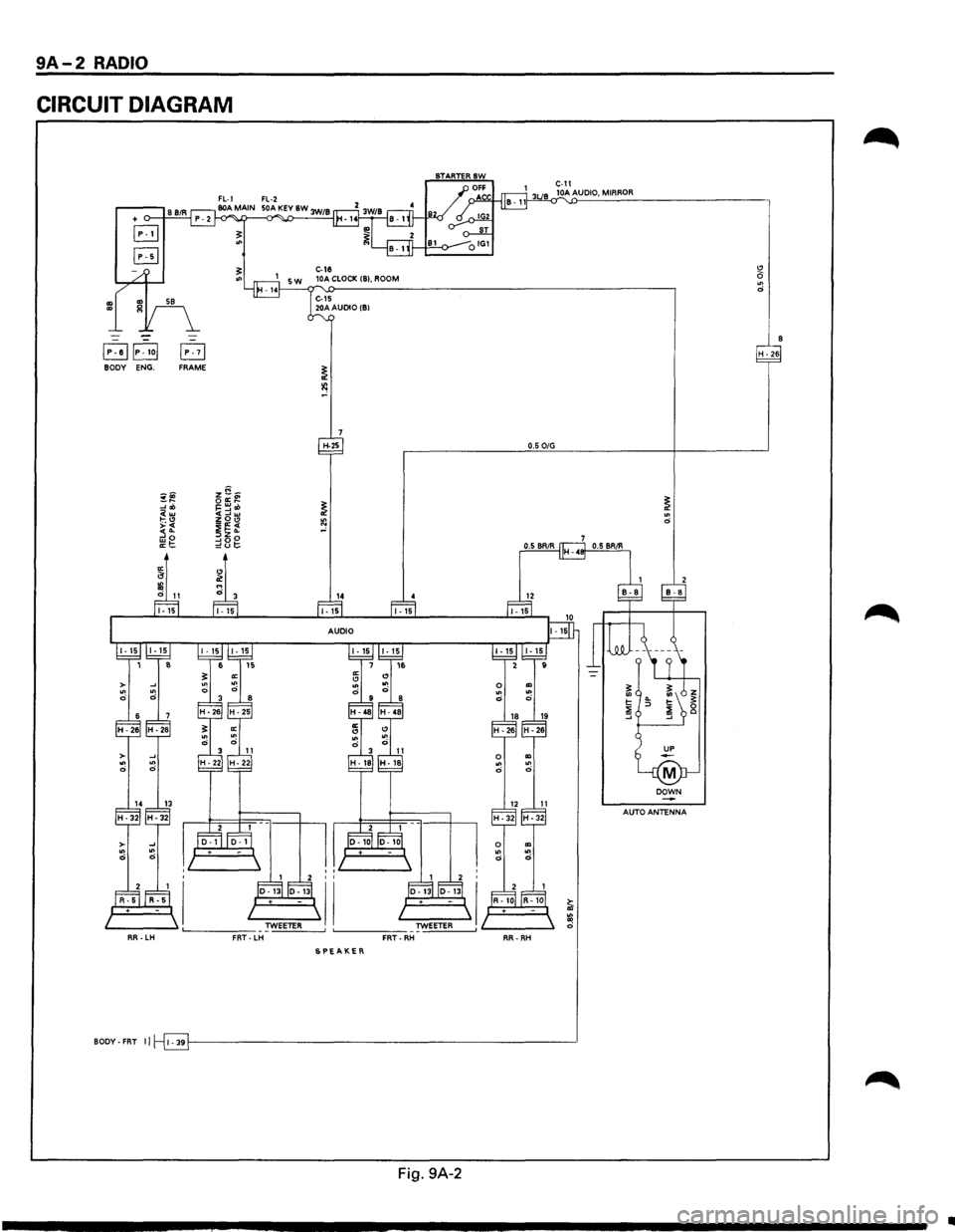
9A-2 RADIO
CIRCUIT DIAGRAM
~~P~1o[ B H · 26 BODY ENG. FRAME
H-25 0.5 0/G
~~ ~~~ ~ ~ :!ob ~==~«> <(w
C> ~
SPEAKER
BODY-FAT II l-39r------------------------------------------------------------"
Fig. 9A-2
..
Page 1579 of 1928
CONNECTOR LIST
~
~
~ ~
Fig. 9A-3
1]1] lo-1ol
[E] IR-101
IH-32IIGRADESIIH-48I
RADIO 9A-3
Page 1580 of 1928
9A-4 RADIO
ANTENNA
AUTO ANTENNA
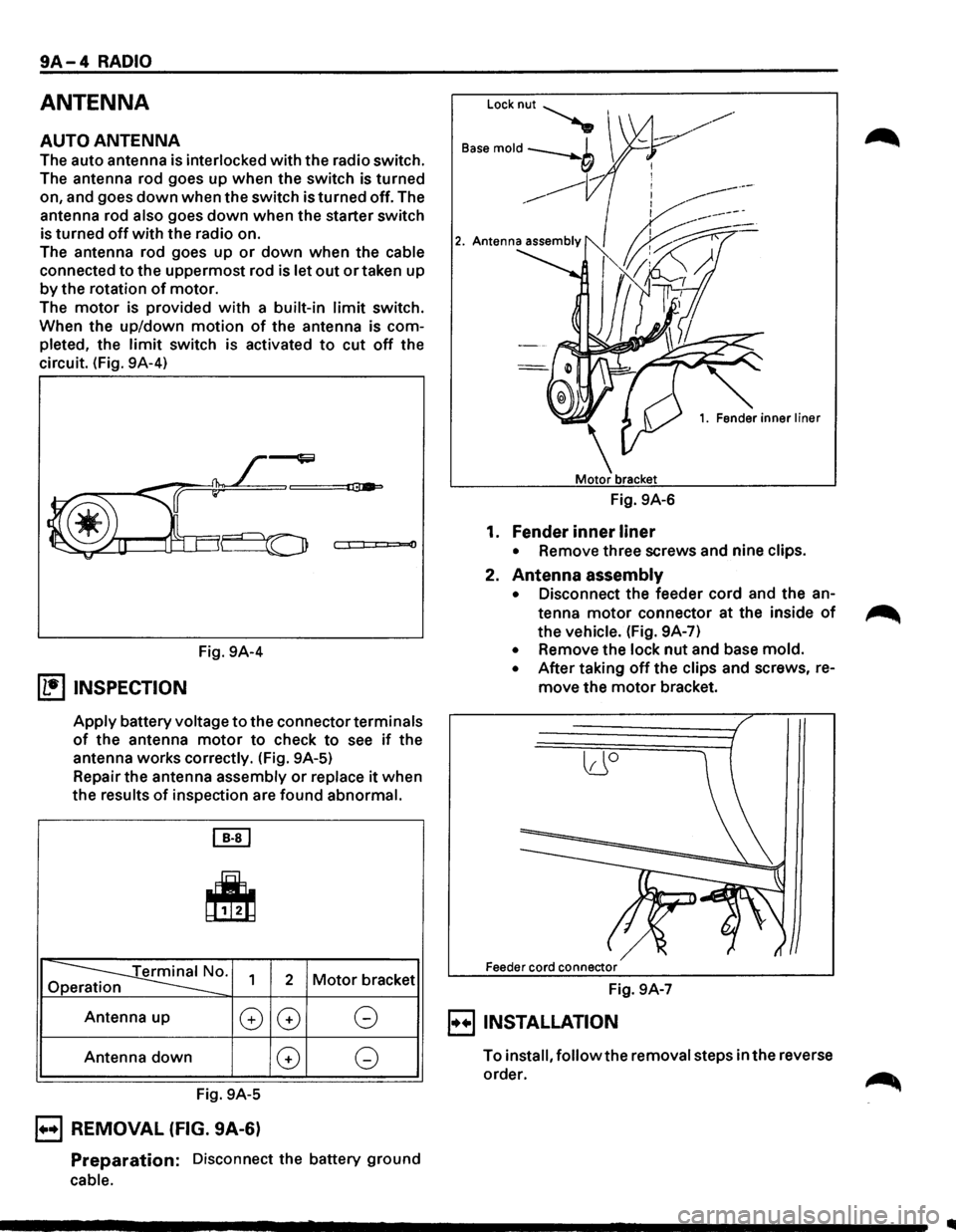
The auto antenna is interlocked with the radio switch.
The antenna rod goes up when the switch is turned
on, and goes
down when the switch is turned off. The
antenna rod
also goes down when the starter switch
is turned
off with the radio on.
The antenna rod goes up
or down when the cable
connected to the uppermost rod is let out or taken up
by the rotation of motor.
The
motor is provided with a built-in limit switch.
When the up/down
motion of the antenna is com
pleted, the
limit switch is activated to cut off the
circuit. (Fig. 9A-4)
0
Fig. 9A-4
(1!] INSPECTION
Apply battery voltage to the connector terminals
of the antenna motor to check to see if the
antenna works correctly. (Fig. 9A-5)
Repair the antenna assembly
or replace it when
the results
of inspection are found abnormal.
[EJ
~
~0. Op 1 2 Motor bracket
Antenna up
G
Antenna down
Fig. 9A-5
B REMOVAL (FIG. 9A-6)
G G
G G
Preparation: Disconnect the battery ground
cable.
Locknut~
B"e mold --b I
___,
------------
1. Fender inner liner
Fig. 9A-6
1. Fender inner liner
• Remove three screws and nine clips.
2. Antenna assembly
• Disconnect the feeder cord and the an
tenna
motor connector at the inside of
the vehicle. (Fig. 9A-7)
• Remove the lock nut and base mold.
• After taking off the clips and screws, re
move the motor bracket.
lJO
Feeder cord connector
Fig. 9A-7
E) INSTALLATION
To install, follow the removal steps in the reverse
order.
![ISUZU TROOPER 1995 Workshop Manual CHASSIS ELECTRICAL 8-385
CONNECTOR LIST
~ I C-4sll C-491 I H-141
elm 8
•
~ ~ 2 i
I H-491 I H-50 II H-531 I H-511
db SJ ~ m ~ ~
IH-521~ [ill] [IT] [ill @][IT]
ITI]@I]
•
~·t~ A ~ ~
I P](/img/61/57183/w960_57183-1574.png "ISUZU TROOPER 1995 Workshop Manual CHASSIS ELECTRICAL 8-385
CONNECTOR LIST
~ I C-4sll C-491 I H-141
elm 8
•
~ ~ 2 i
I H-491 I H-50 II H-531 I H-511
db SJ ~ m ~ ~
IH-521~ [ill] [IT] [ill @][IT]
ITI]@I]
•
~·t~ A ~ ~
I P")
![ISUZU TROOPER 1995 Workshop Manual CONNECTOR LIST
~
~
~ ~
Fig. 9A-3
1]1] lo-1ol
[E] IR-101
IH-32IIGRADESIIH-48I
RADIO 9A-3](/img/61/57183/w960_57183-1578.png "ISUZU TROOPER 1995 Workshop Manual CONNECTOR LIST
~
~
~ ~
Fig. 9A-3
1]1] lo-1ol
[E] IR-101
IH-32IIGRADESIIH-48I
RADIO 9A-3")