ISUZU TROOPER 1995 Workshop Manual
Manufacturer: ISUZU, Model Year: 1995, Model line: TROOPER, Model: ISUZU TROOPER 1995Pages: 1928
Page 1581 of 1928
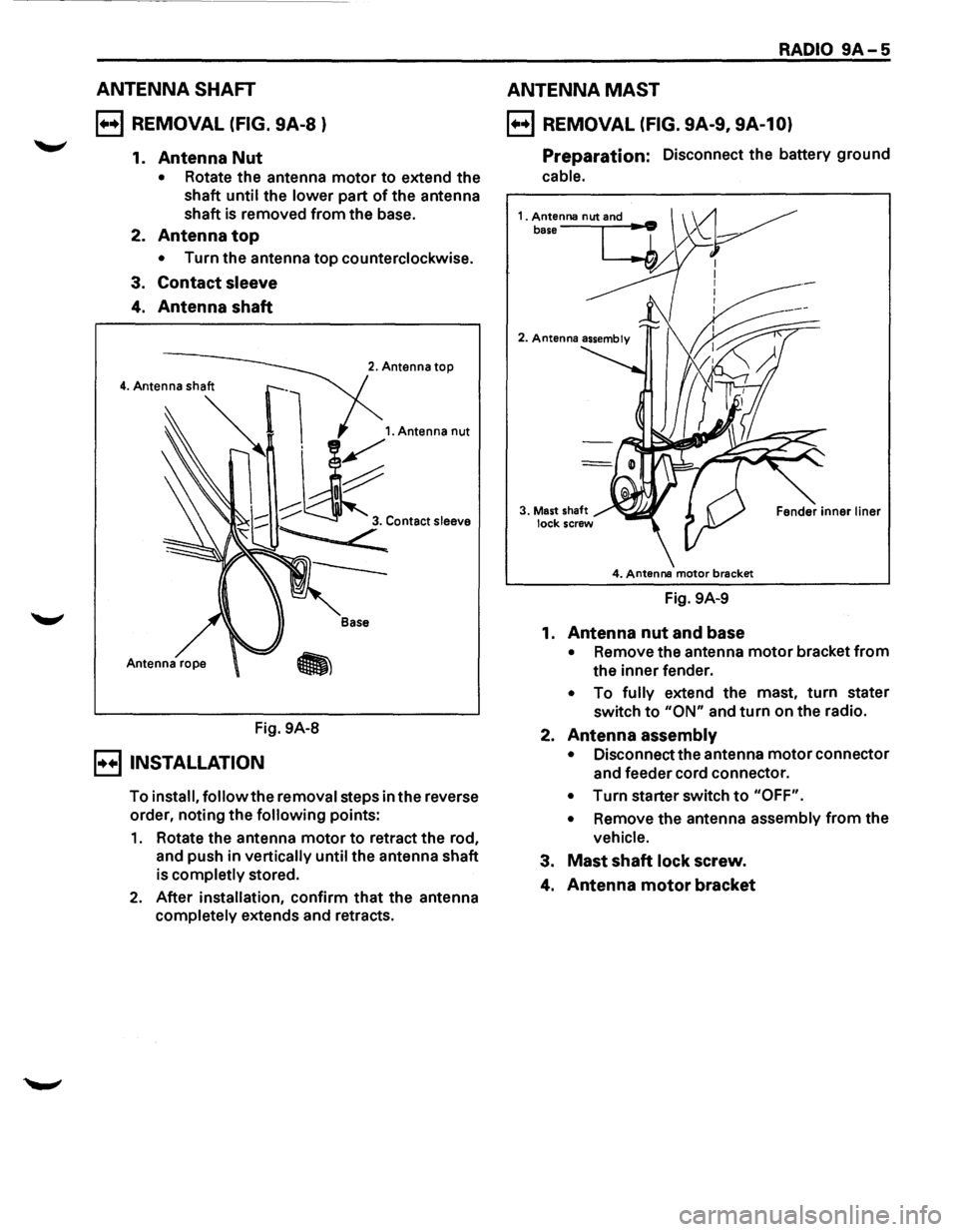
ANTENNA SHAFT
B REMOVAL (FIG. 9A-8 )
1. Antenna Nut
• Rotate the antenna motor to extend the
shaft
until the lower part of the antenna
shaft is removed from the base.
2.
Antenna top
• Turn the antenna top counterclockwise.
3.
Contact sleeve
4. Antenna shaft
Fig. 9A-8
B INSTALLATION
2. Antenna top
Base
To install, follow the removal steps in the reverse
order, noting the
following points:
1. Rotate the antenna motor to retract the rod,
and push in
vertically until the antenna shaft
is
completly stored.
2. After installation, confirm that the antenna
completely extends and retracts.
RADIO 9A-5
ANTENNA MAST
B REMOVAL (FIG. 9A-9, 9A-10)
Preparation: Disconnect the battery ground
cable.
4. Antenna motor brecket
Fig. 9A-9
1.
Antenna nut and base
• Remove the antenna motor bracket from
the inner fender.
• To fully extend the mast, turn stater
switch
to "ON" and turn on the radio.
2.
Antenna assembly
• Disconnect the antenna motor connector
and feeder cord connector.
• Turn starter switch to "OFF".
•
Remove the antenna assembly from the
vehicle.
3. Mast shaft lock screw.
4. Antenna motor bracket
Page 1582 of 1928
9A-6 RADIO
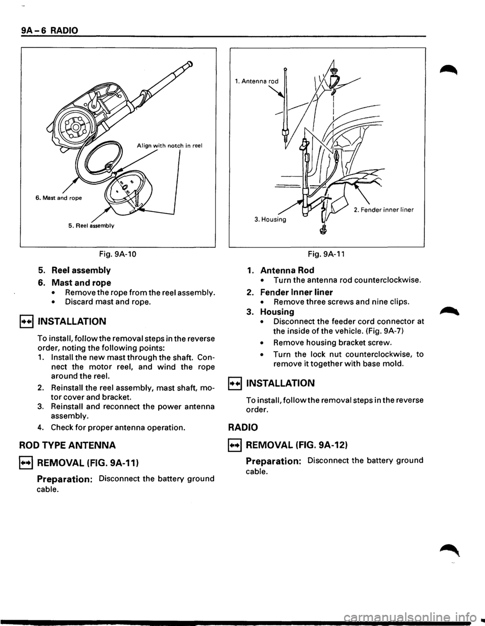
5. Reel assembly
Fig. 9A-10
5. Reel assembly
6. Mast and rope
• Remove the rope from the reel assembly.
•
Discard mast and rope.
B INSTALLATION
To install, follow the removal steps in the reverse
order, noting the
following points:
1. Install the new mast through the shaft. Con
nect the motor reel, and wind the rope
around the
reel.
2. Reinstall the reel assembly, mast shaft, mo
tor cover and bracket.
3. Reinstall and reconnect the power antenna
assembly.
4. Check for proper antenna operation.
ROD TYPE ANTENNA
B REMOVAL (FIG. 9A-11)
Preparation: Disconnect the battery ground
cable.
1. Antenna rod
3. Housing
Fig. 9A-11
1. Antenna Rod
• Turn the antenna rod counterclockwise.
2. Fender Inner liner
• Remove three screws and nine clips.
3. Housing
• Disconnect the feeder cord connector at
the inside
of the vehicle. (Fig. 9A-7)
• Remove housing bracket screw.
• Turn the lock nut counterclockwise, to
remove it together with base mold.
B INSTALLATION
To install, follow the removal steps in the reverse
order.
RADIO
B REMOVAL (FIG. 9A-12)
Preparation: Disconnect the battery ground
cable.
Page 1583 of 1928
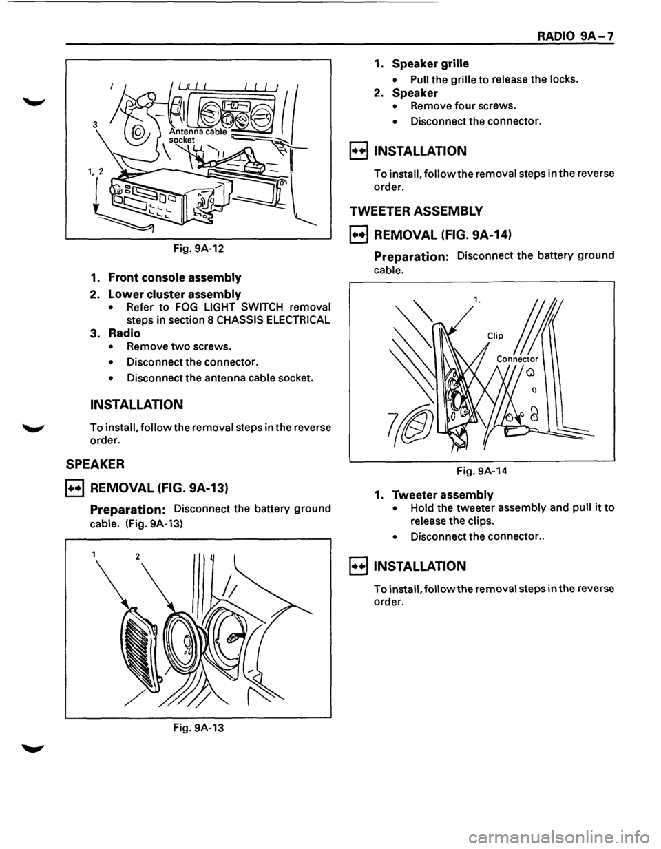
Fig. 9A-12
1. Front console assembly
2. Lower cluster assembly
• Refer to FOG LIGHT SWITCH removal
steps in section 8 CHASSIS ELECTRICAL
3. Radio
• Remove two screws.
• Disconnect the connector.
• Disconnect the antenna cable socket.
INSTALLATION
To install, follow the removal steps in the reverse
order.
SPEAKER
B REMOVAL (FIG. 9A-13)
Preparation: Disconnect the battery ground
cable. (Fig. 9A-13)
Fig. 9A-13
RADIO 9A-7
1. Speaker grille
• Pull the grille to release the locks.
2. Speaker
• Remove four screws.
• Disconnect the connector.
8 INSTALLATION
To install, followthe removal steps in the reverse
order.
TWEETER ASSEMBLY
B REMOVAL (FIG. 9A-14)
Preparation: Disconnect the battery ground
cable.
l. CUp j
Connector
0
Fig. 9A-14
1. Tweeter assembly
• Hold the tweeter assembly and pull it to
release the clips.
•
Disconnect the connector ..
8 INSTALLATION
To install, followthe removal steps in the reverse
order.
Page 1584 of 1928
MEMO
Page 1585 of 1928
---------------~-~---
CRUISE CONTROL 9B-1
SECTION 98
CRUISE CONTROL
CONTENTS
General description ................................ .
Parts location .......................................... .
Circuit diagram ....................................... .
Diagnosis ................................................. .
On-vehicle service ................................. ..
Brake switch adjustment ................ ..
Clutch switch adjustment ................ .
Actuator
cable adjustment .............. .
Starter switch ................................... .
Cruise control main switch .............. .
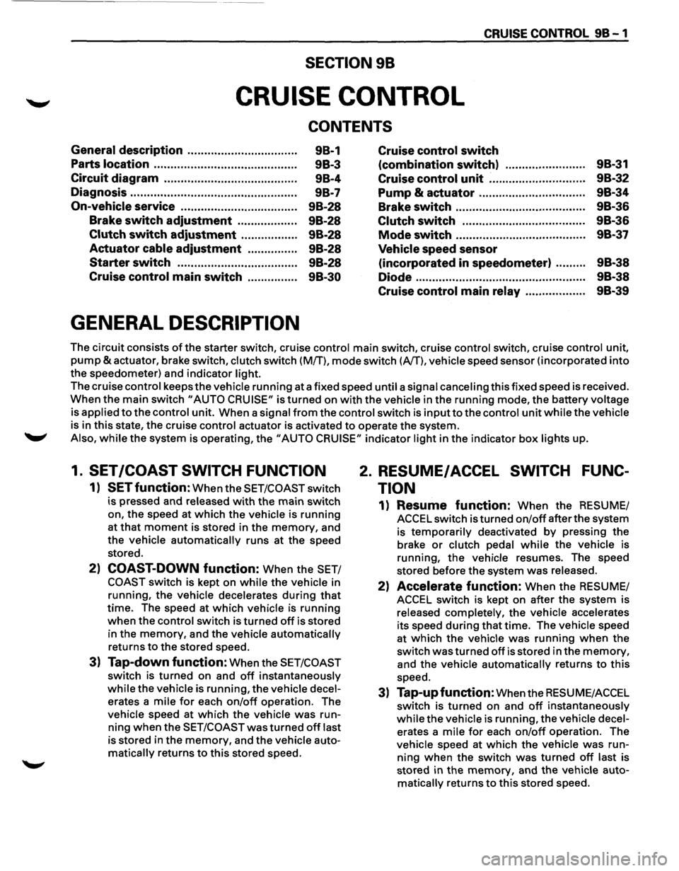
GENERAL DESCRIPTION
98-1
9B-3
98-4
9B-7
98-28
9B-28
9B-28
9B-28
9B-28
9B-30 Cruise
control
switch
(combination switch) ........................ 98-31
Cruise control unit .......................... ... 9B-32
Pump
& actuator .................. .............. 9B-34
Brake switch ....................................... 9B-36
Clutch switch .............................. ....... 9B-36
Mode switch .. .. .. .. .. .. .. .. .. .. .. .. .. .. .. .. .. .. .. . 9B-37
Vehicle speed sensor
(incorporated in speedometer) ......... 9B-38
Diode
.. .. .. .. .. .. . .. .. .. .. .. . .. .. .. .. .. .. .. .. .. .. . .. .. .. 9B-38
Cruise control main relay .................. 9B-39
The circuit consists of the starter switch, cruise control main switch, cruise control switch, cruise control unit,
pump &actuator, brake switch, clutch switch (M/T), mode switch (A/T), vehicle speed sensor (incorporated into
the speedometer) and indicator light.
The cruise control keeps
the vehicle running at a fixed speed until a signal canceling this fixed speed is received.
When the main switch "AUTO CRUISE" is turned on with the vehicle in the running mode, the battery voltage
is applied
to the control unit. When a signal from the control switch is input to the control unit while the vehicle
is in this state, the cruise control actuator is activated to operate the system .
.._, Also, while the system is operating, the "AUTO CRUISE" indicator light in the indicator box lights up.
1. SET /COAST SWITCH FUNCTION
1) SET function: When the SET/COAST switch
is pressed and released
with the main switch
on, the speed at
which the vehicle is running
at that moment is stored in the memory, and
the vehicle
automatically runs at the speed
stored.
2) COAST-DOWN function: When the SET/
COAST switch is kept on while the vehicle in
running, the vehicle decelerates
during that
time. The speed at which vehicle is running
when the control switch is turned off is stored
in the
memory, and the vehicle automatically
returns
to the stored speed.
3) Tap-down function: When the SET/COAST
switch is turned on and off instantaneously
while the vehicle is running, the vehicle decel
erates a mile for each on/off operation. The
vehicle speed at
which the vehicle was run
ning when the SET/COAST was turned off last
is stored in the
memory, and the vehicle auto
matically returns to this stored speed.
2. RESUME/ ACCEL SWITCH FUNC
TION
1) Resume function: When the RESUME/
ACCEL switch is turned
on/off after the system
is
temporarily deactivated by pressing the
brake or clutch pedal while the vehicle is
running,
the vehicle resumes. The speed
stored before the system
was released.
2) Accelerate function: When the RESUME/
ACCEL switch is kept on after the system is
released completely, the vehicle accelerates
its speed
during that time. The vehicle speed
at
which the vehicle was running when the
switch
was turned off is stored in the memory,
and the vehicle automatically returns to this
speed.
3) Tap-up function: When the RESU ME/ACCEL
switch is
turned on and off instantaneously
while the vehicle is running, the vehicle decel
erates a mile for each on/off operation. The
vehicle speed at
which the vehicle was run
ning when the switch was turned off last is
stored in the
memory, and the vehicle auto
matically returns to this stored speed.
Page 1586 of 1928
98-2 CRUISE CONTROL
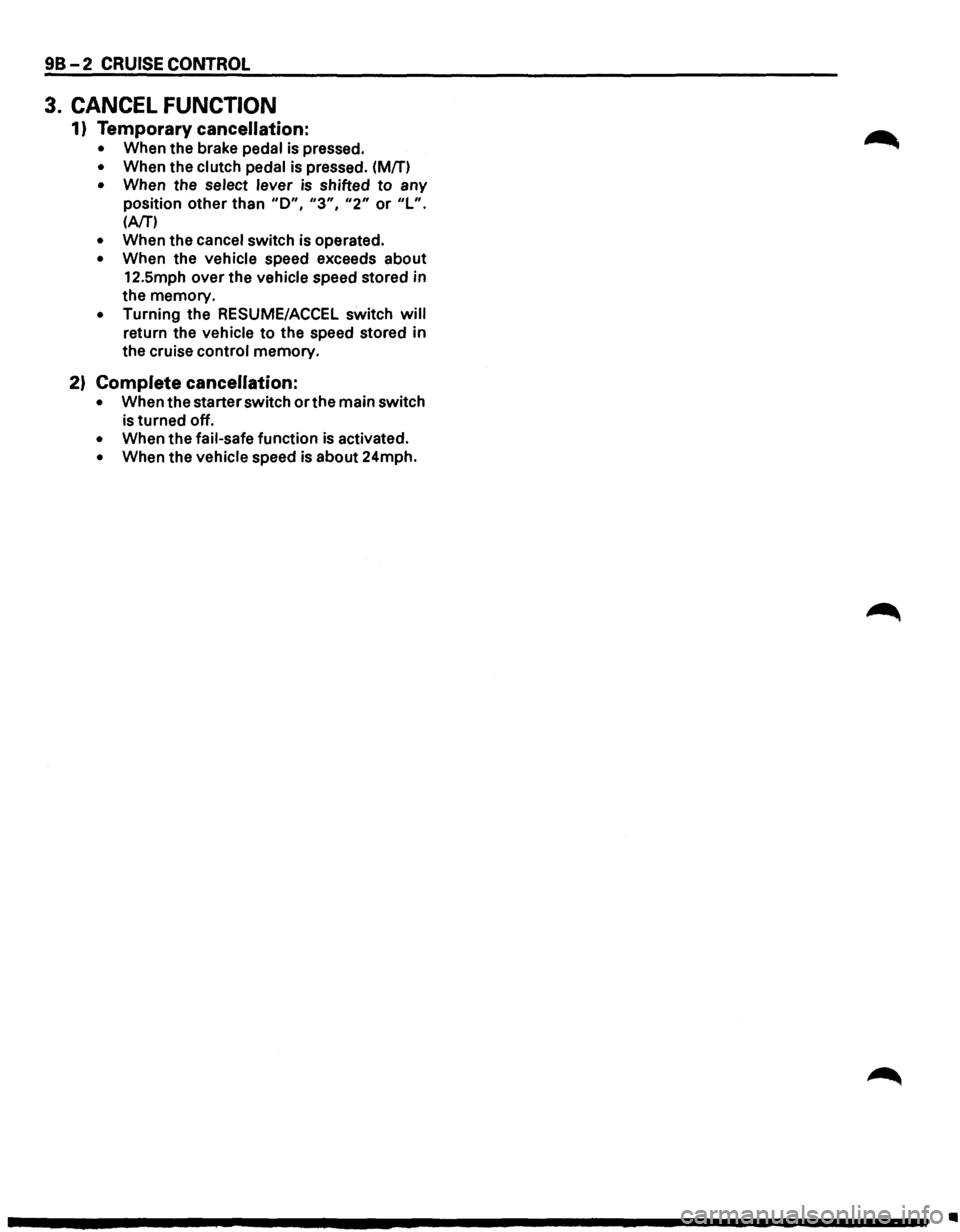
3. CANCEL FUNCTION
1) Temporary cancellation:
• When the brake pedal is pressed.
• When the clutch pedal is pressed. (Mfn
• When the select lever is shifted to any
position other than
"D", "3", "2" or "L".
(AfT')
• When the cancel switch is operated.
• When the vehicle speed exceeds about
12.5mph over the vehicle speed stored in
the memory.
• Turning the RESUME/ACCEL switch will
return the vehicle to the speed stored in
the cruise control memory.
2) Complete cancellation:
• When the starter switch or the main switch
is turned off.
• When the fail-safe function is activated.
• When the vehicle speed is about 24mph.
Ill
Page 1587 of 1928
, cCi" <0 CD I ....
( (
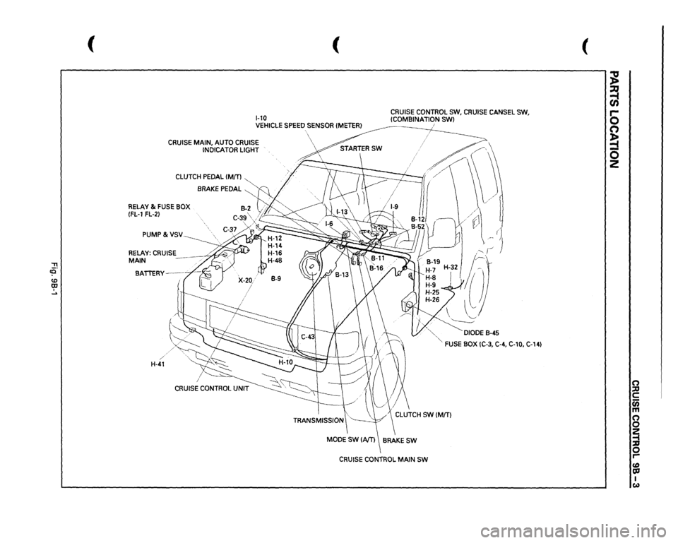
1-10
CRUISE CONTROL SW,
CRUISE
CANSEL SW,
!COMBINATION
SWl
VEHICLE
SPEED
SENSOR
!METER}
i
CRUISE MAIN, AUTO CRUISE
INDICATOR LIGHT
CLUTCH
PEDAL
IM[T)
~
. //
BRAKE PEDAL
~~
RELAY &
FUSE BOX
B-2
vi"""
(FL-1
FL-2}
C-3g\j;~
PUMP&VSV
RELAY:
CRUISE
MAIN BATTERY--
/
H-41
··,.
,:-,
\
·.,"-
~DIODE
8-45
'"-FUSE
BOX IC-3, C-4, C-10,
C-14)
CRUISE
CONTROL
MAIN
SW
(
~ ~ 0 n ~ 0 z
n ::D c c;; m n 0 ~ 0 r-fD OJ I w
Page 1588 of 1928
![ISUZU TROOPER 1995 Workshop Manual .,
~[~}
0
U)
..
m
.,
0
z
()
-
0
"
~
m
::g
"
c
I
+
I
;,
iii
~[]"
00
0
:I:
~
,.
z
" 0
!!
c:
(")
a
1@}1
..
=i
:u
"
~
c
0.5LfY
""
c
u;
-
m
-n
~~
)](/img/61/57183/w960_57183-1587.png "ISUZU TROOPER 1995 Workshop Manual .,
~[~}
0
U)
..
m
.,
0
z
()
-
0
\"
~
m
::g
\"
c
I
+
I
;,
iii
~[]\"
00
0
:I:
~
,.
z
\" 0
!!
c:
(\")
a
1@}1
..
=i
:u
\"
~
c
0.5LfY
\"\"
c
u;
-
m
-n
~~
)")
.,
~[~}
0
U)
..
m
.,
0
z
(')
-
0
"'
~
m
::g
"'
c
I
+
I
;,
iii
~[]"
00
0
:I:
~
,.
z
"' 0
!'!
c:
(")
a
1@}1
..
=i
:u
"'
~
c
0.5LfY
""
c
u;
-
m
-n
~~
)>
(")
~.:.
Q
0
0
'!::
'!::
CRUISE
CONTROl
MAIN
fNi
l~
!:
::g
2
z
"'
)>
-1
RELAY;TAll.lC)
1 e
3:
:u
lTO PAGE
8-78)
~
0 .-
.. ~
-~
.. ~
L___JI.,-L__Q
;~
l.,-11
I
lzl
1.!.1
1.!..1
I
0 .. ..
..
..
n
~
"'
"
s;
..
O.SGR/1.
TCMlB4l
....
..
= 0
m
m
•
lTO PAGE
8-195)
"'
g
..
..
z
~
~
:i1
0.51/W
~
~
li
::!!
I
~'==I
I ;
-
(Q
~
(0
;:
a:J
h:l
I
28
0.58
I
..
N
~
6-r
r ;:.:.
0.581\'11
~:::::::~
..
~
~ ..
J:w
!;.
m
_,
...
c
~
~ ~ i5
a.
~
;z
1i
(')
"
§
-·
I
O.SW/1.
J
I I
r-n
......
~
r=TI
I -
II-
I
...........
I
0 ilo .. l!! .,
·-
li
li
~
1.25
B
0.58
I%Tl
-
0.58
rr::l
I
;---..
I C11
.U...fl%1
0.5 11M!
I
I
I~
O.SSGIW
O.SIVY
o.as
RIB
0.5 GIVG
----------------------------------------------------------------------r-\
----,
CANCElfNi
Q.UTCH
fNi
1
.. ~
._____.
LL-J..
OSIVY
J~H~L
j~
------------------------------------------------------------------------\
--------------------------J
) )
)
•
Page 1589 of 1928
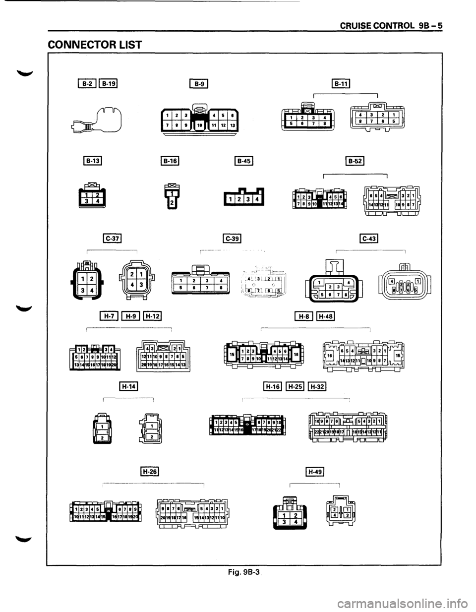
CONNECTOR LIST
4 5 •
11 1Z 13
Fig. 98-3
~
~
CRUISE CONTROL 98-5
Page 1590 of 1928
![ISUZU TROOPER 1995 Workshop Manual 98-6 CRUISE CONTROL
[till [ill [ill CITHEHEJ I P-10 I I X-201
r--~ ------
• II
~ I(g) Ei±8 4 -6
Fig.
98-4
..](/img/61/57183/w960_57183-1589.png "ISUZU TROOPER 1995 Workshop Manual 98-6 CRUISE CONTROL
[till [ill [ill CITHEHEJ I P-10 I I X-201
r--~ ------
• II
~ I(g) Ei±8 4 -6
Fig.
98-4
..")
98-6 CRUISE CONTROL
[till [ill [ill CITHEHEJ I P-10 I I X-201
r--~ ------
• II
~ I(g) Ei±8 4 -6
Fig.
98-4
..