transmission ISUZU TROOPER 1995 Workshop Manual
[x] Cancel search | Manufacturer: ISUZU, Model Year: 1995, Model line: TROOPER, Model: ISUZU TROOPER 1995Pages: 1928
Page 948 of 1928
7A-76 AUTOMATIC TRANSMISSION (4L30-E)
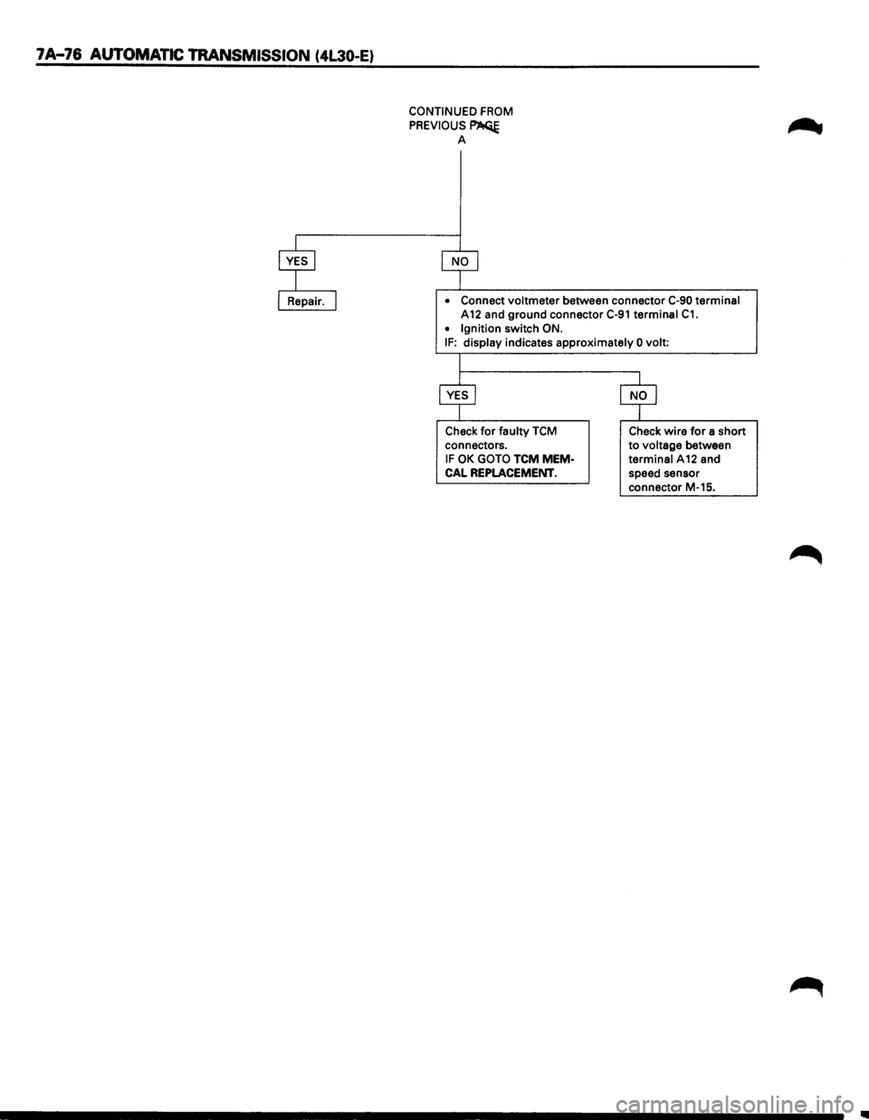
CONTINUED FROM
PREVIOUS~ A
• Connect voltmeter between connector C-90 terminal
A 12 and ground connector C-91 terminal C1.
• Ignition switch ON. IF: display indicates approximately 0 volt:
Check
for faulty TCM
connectors.
IF OK GOTO TCM MEM·
CAL REPLACEMENT.
Check wire for a short
to voltage between
terminal A12 and
speed sensor
connector M-15.
Page 949 of 1928
AUTOMATIC TRANSMISSION (4L30-E) 7A-77
MEMO
Page 950 of 1928
7A-78 AUTOMATIC TRANSMISSION (4L30-E)
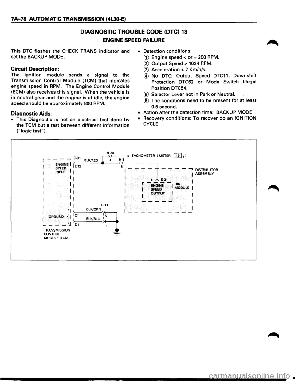
DIAGNOSTIC TROUBLE CODE (DTC) 13
ENGINE SPEED FAILURE
This DTC flashes the CHECK TRANS indicator and
set the BACKUP
MODE.
Circuit Description:
The ignition module sends a signal to the
Transmission
Control Module (TCM) that indicates
engine speed in
RPM. The Engine Control Module
(ECM) also receives this signal. When the vehicle is
in
neutral gear and the engine is at idle, the engine
speed
should be approximately 800 RPM.
Diagnostic Aids:
• This Diagnostic is not an electrical test done by
the TCM but a test between different information
("logic test"). •
Detection
conditions:
CD Engine speed< or= 200 RPM.
@ Output Speed > 1024 RPM.
@ Acceleration > 2 Km/h/s.
@ No DTC: Output Speed DTC11, Downshift
Protection DTC62 or Mode Switch Illegal
Position DTC54.
@ Selector Lever not in Park or Neutral.
@ The conditions need to be present for at least
0.5
second.
• Action after the detection time: BACKUP MODE
•
Recovery conditions: To recover do an IGNITION
CYCLE
>--
-------t~lt--H--4~>-_4=.--+· TACHOMETER (METER [!1]31 r - - - -C-91 BLK/RED ~ H·S
I ENGINE I fD12 (A SPEED I I - - - - - - - --, DISTRIBUTOR I INPUT I I ASSEMBLy
I I I I 4 E-21 l I 1 r----ots 1 I I ENGINE I MODULE I
I II I I SPeED I OUTPUT 1
I II I ~---..J I
I I I H-11 I I
I GROUND {II fc1 BLK!ORN~q I_---------
I ) BLK/BLU ~ 1
'----j D1 TRANSMISSION CONTROL MODULE (TCMI
..
Page 951 of 1928
AUTOMATIC TRANSMISSION (4L30-E) 7A-79
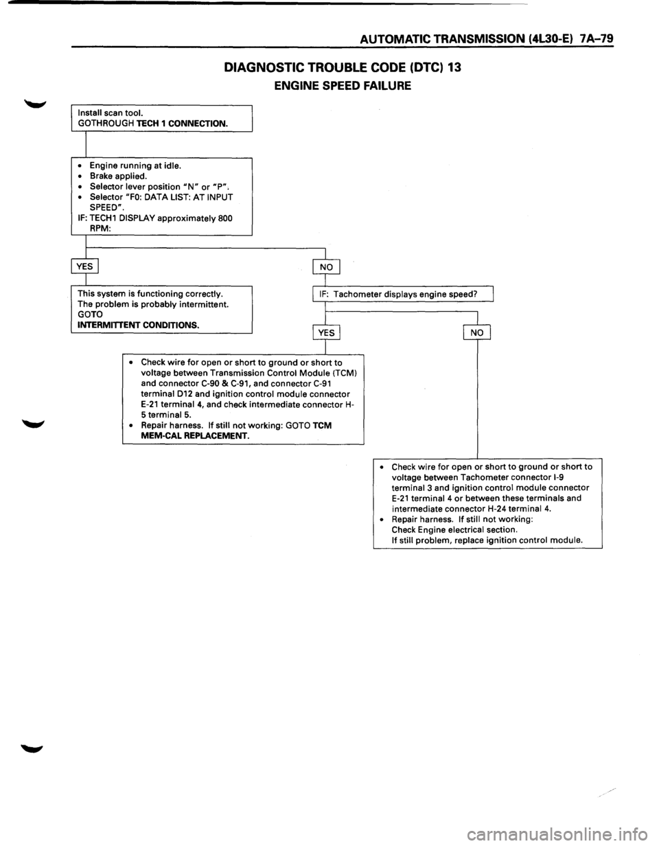
DIAGNOSTIC TROUBLE CODE (DTC) 13
ENGINE SPEED FAILURE
Install scan tool.
GOTHROUGH
TECH 1 CONNECTION.
I
• Engine running at idle.
• Brake applied.
• Selector lever
position "N" or "P", • Selector "FO: DATA LIST: AT INPUT SPEED".
IF: TECH1 DISPLAY approximately 800 RPM:
I
$
This system is functioning correctly. The problem is probably intermittent. GOTO
I IF: Tachometer displays engine speed? I
'~------------------~
$ c§J
INTERMITTENT CONDITIONS.
r---------------------------------~----~ • Check wire for open or short to ground or short to voltage between Transmission Control Module (TCM) and connector C-90 & C-91, and connector C-91 terminal D12 and ignition control module connector E-21 terminal 4, and check intermediate connector H-5 terminal 5.
• Repair harness. If still not working: GOTO TCM MEM-CAL REPLACEMENT.
• Check wire for open or short to ground or short to voltage between Tachometer connector 1-9 terminal 3 and ignition control module connector E-21 terminal 4 or between these terminals and
intermediate connector H-24
terminal 4. • Repair harness. If still not working: Check Engine electrical section. If still problem, replace ignition control module.
Page 952 of 1928
1 A-80 AUTOMATIC TRANSMISSION (4L30-E)
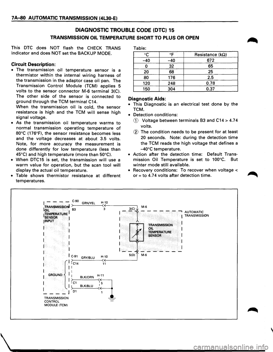
DIAGNOSTIC TROUBLE CODE (DTC) 15
TRANSMISSION OIL TEMPERATURE SHORT TO PLUS OR OPEN
This DTC does NOT flash the CHECK TRANS
indicator and does NOT set the BACKUP MODE.
Circuit Description:
• The transmission oil temperature sensor is a
thermistor within the internal wiring harness of
the transmission in the adaptor case oil pan. The
Transmission Control Module (TCM) applies 5
volts to the sensor connector M-6 terminal 3(C).
The
other side of the sensor is connected to
ground through the TCM terminal C14.
When the transmission oil is cold, the sensor
resistance is high and the TCM will sense high
signal voltage.
• As the transmission oil temperature warms to
normal transmission operating temperature of
80°C (176°F), the sensor resistance becomes less
and
the voltage decreases at about 3.5 volts.
Note,
for more accuracy the measurement is
done differently for low temperature (less than
45°C) and high temperature (more than 50°C).
•
When DTC15 is set, the transmission will use a
warm value for operation, but the scan tool will
display the actual oil temperature.
• Table shows thermistor resistance at different
temperatures.
Table:
oc OF Resistance (kQ)
-40 -40 672
0 32 65
20 68 25
80 176
2.5
120 248 0.78
150 304 0.37
Diagnostic Aids:
• This Diagnostic is an electrical test done by the
TCM.
• Detection conditions:
CD Voltage between terminals B3 and C14 > 4.74
volts.
@ The condition needs to be present for at least
20 seconds. Note: during the detection time
the TCM reads the high voltage that defines a
-40°C temperature.
• Action after the detection time: Default Trans
mission Oil Temperature is set to 100°C. But
winter mode still available.
• Recovery conditions: To recover when voltage <
or= to 4.74 volts after detection time.
f - ---C-90 GRN/YEL H-10 ITRANSMISSIONI >---'----<•((,--------3-(C--,) I M-6 to,,IL ~ 3 ~
ltEMf!EAATURE I I --1---- ---, AUTOMATIC
SENSOR I I I TRANSMISSION
llNPUT
I
I I
I TRANSMISSION L.... Oil I
I I I ~ TEMPERATURE
I I I / SENSOR I
I I I I
r I I __ _. _______ I
I I C-91 H-10 5(0) 1' M-6 GRY/BLU I ,. I >>---_:__--< < I IC14 11
I II
II I GROUND
I BLK/ORN H-11
1 1?c1 ~q I '-. I ~>--B_L__cKI_BL_U--<~ 5
----J 01
1
TRANSMISSION
CONTROL
MODULE ITCM)
Page 953 of 1928
AUTOMATIC TRANSMISSION (4L30-E) 7 A-81
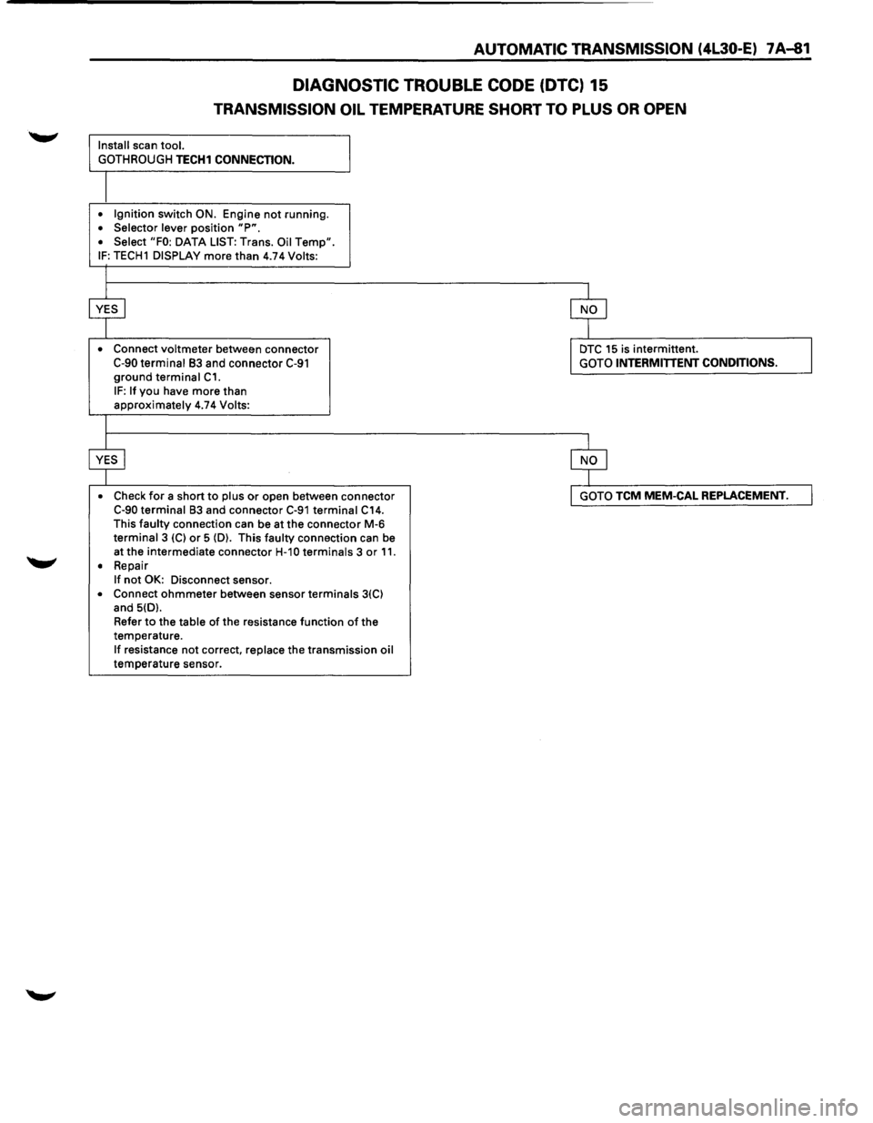
DIAGNOSTIC TROUBLE CODE (DTC) 15
TRANSMISSION OIL TEMPERATURE SHORT TO PLUS OR OPEN
Install scan tool.
GOTHROUGH
TECH1 CONNECTION.
• Ignition switch ON. Engine not running. • Selector lever position "P". • Select "FO: DATA LIST: Trans. Oil Temp". IF: TECH1 DISPLAY more than 4.74 Volts:
•
Connect voltmeter between connector C-90 terminal 83 and connector C-91 ground terminal C1.
IF: If you have more than approximately 4.74 Volts:
• Check
for a short to plus or open between connector C-90 terminal 83 and connector C-91 terminal C14. This faulty connection can be at the connector M-6 terminal 3 (C) or 5 (D). This faulty connection can be
at the intermediate connector
H-1 0 terminals 3 or 11. • Repair If not OK: Disconnect sensor.
• Connect ohmmeter between sensor terminals 3(C) and 5(D).
Refer
to the table of the resistance function of the
temperature.
If resistance not correct, replace the transmission oil temperature sensor.
DTC 15 is intermittent. GOTO INTERMITTENT CONDITIONS.
GOTO TCM MEM-CAL REPLACEMENT.
Page 954 of 1928
7 A-82 AUTOMATIC TRANSMISSION (4L30-E)
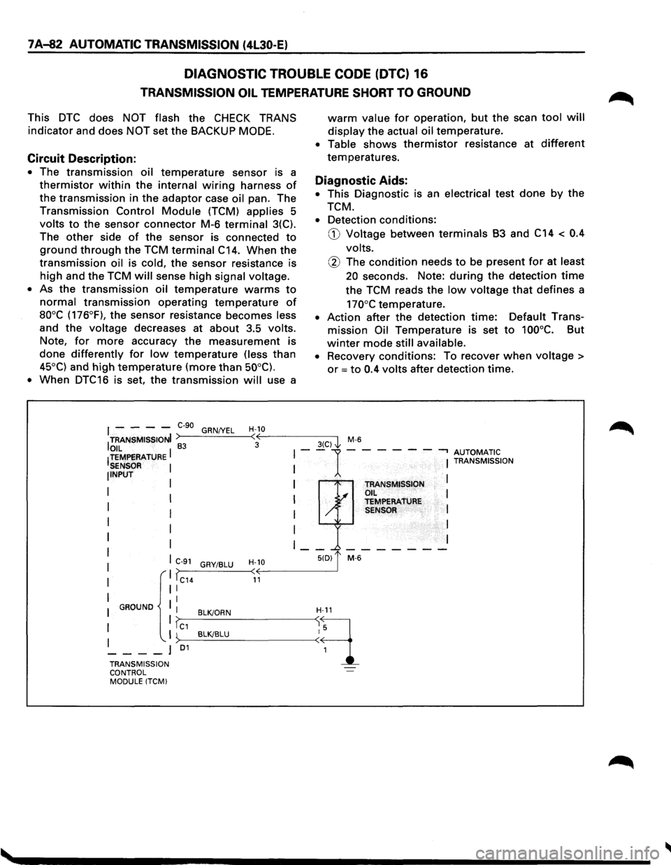
DIAGNOSTIC TROUBLE CODE (DTC) 16
TRANSMISSION OIL TEMPERATURE SHORT TO GROUND
This DTC does NOT flash the CHECK TRANS
indicator and does NOT set the BACKUP MODE.
Circuit Description:
• The transmission oil temperature sensor is a
thermistor within the internal wiring harness of
the transmission in the adaptor case oil pan. The
Transmission Control Module (TCM) applies 5
volts to the sensor connector M-6 terminal 3(C).
The
other side of the sensor is connected to
ground through the TCM terminal C14. When the
transmission oil is cold, the sensor resistance is
high and the TCM will sense high signal voltage.
•
As the transmission oil temperature warms to
normal transmission operating temperature of
aooc (176°F), the sensor resistance becomes less
and the voltage decreases at about 3.5 volts.
Note, for more accuracy the measurement is
done differently for low temperature (less than
45°C) and high temperature (more than 50°C).
•
When DTC16 is set, the transmission will use a
warm value for operation, but the scan tool will
display the actual oil temperature.
• Table shows thermistor resistance at different
temperatures.
Diagnostic Aids:
• This Diagnostic is an electrical test done by the
TCM.
• Detection conditions:
G) Voltage between terminals B3 and C14 < 0.4
volts.
@ The condition needs to be present for at least
20 seconds. Note: during the detection time
the TCM reads the low voltage that defines a
170°C temperature.
• Action after the detection time: Default Trans
mission Oil Temperature is set to 100°C. But
winter mode still available.
•
Recovery conditions: To recover when voltage >
or = to 0.4 volts after detection time.
I - - - -e-go GRN/YEL H-10
ITRANSMISSIONI >----'-----<:·oE---------3-(C-)-,'1 M-6
OIL I 83 I--1-- --- -.., AUTOMATIC !TEMPERATURE I I TRANSMISSION SENSOR NPUT I TRANSMISSION I .I OIL I I y TEMPERATURE I / SENSOR I
I
I I
I __ _.-------
C>--9_1_G_RY_I_BL_U_-
TRANSMISSION ~·· ... -l
CONTROL MODULE !TCM)
Page 955 of 1928
AUTOMATIC TRANSMISSION (4L30-E) 7 A-83
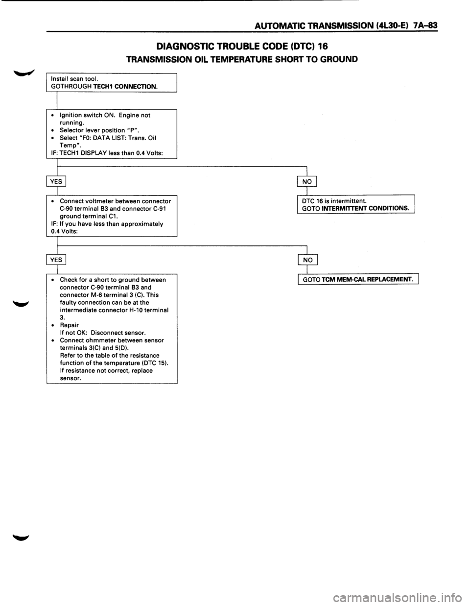
DIAGNOSTIC TROUBLE CODE (DTC) 16
TRANSMISSION OIL TEMPERATURE SHORT TO GROUND
Install scan tool.
GOTH ROUGH
TECH1 CONNECTION.
• Ignition switch ON. Engine not running.
• Selector lever position "P". • Select "FO: DATA LIST: Trans. Oil Temp".
IF: TECH1 DISPLAY less than 0.4 Volts:
• Connect
voltmeter between connector C-90 terminal 83 and connector C-91 ground terminal C1. IF: If you have less than approximately 0.4 Volts:
• Check
for a short to ground between
connector C-90 terminal 83 and
connector M-6 terminal 3 {C). This faulty connection can be at the
intermediate connector
H-10 terminal 3.
• Repair If not OK: Disconnect sensor. • Connect ohmmeter between sensor terminals 3{C) and 5{D).
Refer
to the table of the resistance
function of the temperature {DTC 15).
If resistance not correct, replace sensor.
DTC 16 is intermittent. GOTO INTERMITTENT CONDITIONS.
GOTO TCM MEM-CAL REPLACEMENT.
Page 956 of 1928
7 A-84 AUTOMATIC TRANSMISSION (4L30-E)
DIAGNOSTIC TROUBLE CODE (DTC) 21
THROTTLE POSITION SENSOR SHORT TO PLUS OR OPEN
This DTC flashes the CHECK TRANS indicator and
sets
the BACKUP MODE.
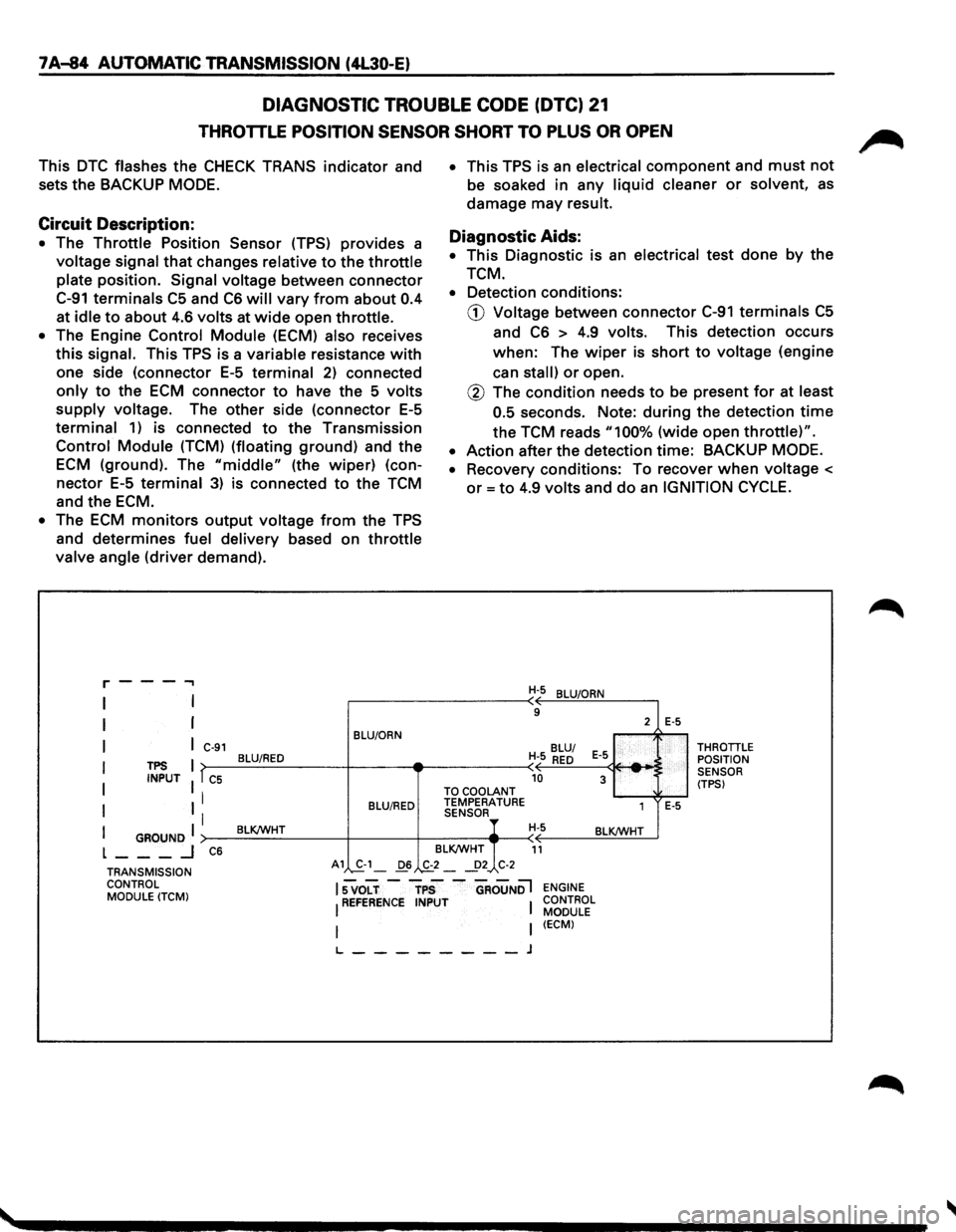
Circuit Description:
• The Throttle Position Sensor (TPS) provides a
voltage signal that changes relative to the throttle
plate position. Signal voltage between connector
C-91 terminals C5 and C6 will vary from about 0.4
at idle to about 4.6 volts at wide open throttle.
• The Engine Control Module (ECM) also receives
this signal. This TPS is a variable resistance with
one side (connector E-5 terminal 2) connected
only to the ECM connector to have the 5 volts
supply voltage. The other side (connector E-5
terminal 1) is connected to the Transmission
Control Module (TCM) (floating ground) and the
ECM (ground). The "middle" (the wiper) (con
nector E-5 terminal 3) is connected to the TCM
and
the ECM.
• The ECM monitors output voltage from the TPS
and determines fuel delivery based on throttle
valve angle (driver demand).
r---...,
I
I
I
I
I
I
TPS INPUT
I GROUND I L ___ _j
C-91
T C5
I
I
C6
BLU/ORN
BLU/RED
BLU/RED
BLK/WHT
• This TPS is an electrical component and must not
be soaked in any liquid cleaner or solvent, as
damage may result.
Diagnostic Aids:
• This Diagnostic is an electrical test done by the
TCM.
• Detection conditions:
CD Voltage between connector C-91 terminals C5
and C6 > 4.9 volts. This detection occurs
when: The wiper is short to voltage (engine
can
stall) or open.
@ The condition needs to be present for at least
0.5
seconds. Note: during the detection time
the TCM reads "100% (wide open throttle)".
• Action after the detection time: BACKUP MODE.
•
Recovery conditions: To recover when voltage <
or= to 4.9 volts and do an IGNITION CYCLE.
H-5 BLU/ORN
9
BLU/
H-5
RED E-5
-10 3 TO COOLANT TEMPERATURE
1 SENSOR H-5 BLK/WHT
BLK/WHT
11
2 E-5
E-5
THROTTLE POSITION
SENSOR
(TPS)
TRANSMISSION CONTROL MODULE
(TCM)
A1 S.-1_ 06 .,&_2 _ _!>2 C-2
lsvoLT-rps -aRouNDl ENGINE
I REFERENCE INPUT I CONTROL MODULE
I (ECM)
L--------J
Page 957 of 1928
AUTOMATIC TRANSMISSION (4L30-E) 7A-85
DIAGNOSTIC TROUBLE CODE (DTC) 21
THROTTLE POSITION SENSOR SHORT TO PLUS OR OPEN
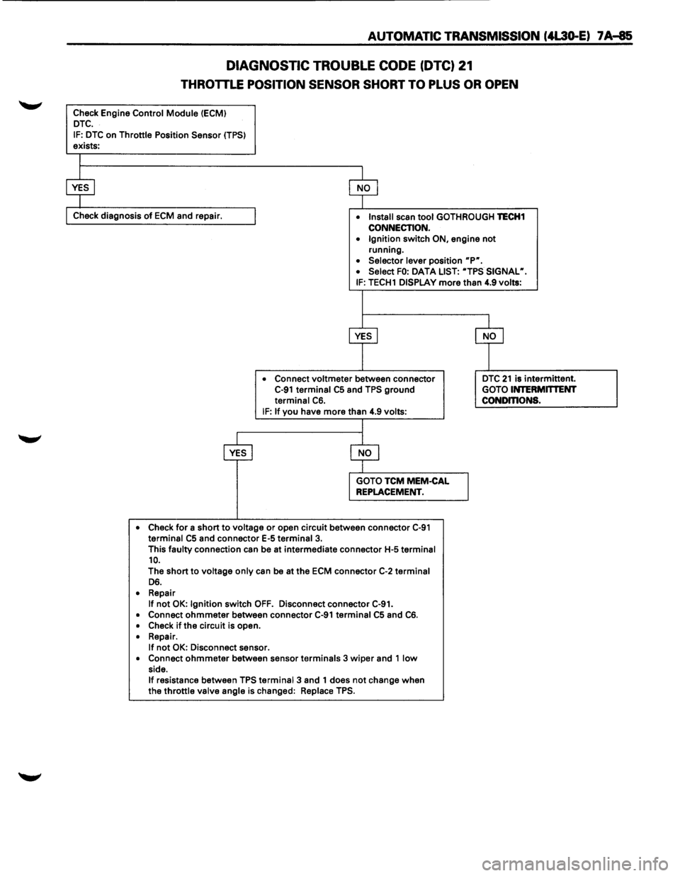
Check Engine Control Module (ECMI DTC.
IF: DTC on Throttle Position Sensor (TPSI exists:
Check diagnosis of ECM and repair. • Install scan tool GOTHROUGH TECH1
CONNECTION. • Ignition switch ON, engine not
running.
• Selector lever position up•.
• Select FO: DATA LIST: "TPS SIGNAL•. IF: TECH1 DISPLAY more than 4.9 volts:
• Connect
voltmeter between connector C-91 terminal C5 and TPS ground
terminal C6. IF: If you have more than 4.9 volts:
• Check
for a short to voltage or open circuit between connector C-91 terminal C5 and connector E-5 terminal 3.
This faulty connection can be at intermediate connector H-5 terminal 10.
The short to voltage only can be at the ECM connector C-2 terminal D6.
• Repair If not OK: Ignition switch OFF. Disconnect connector C-91.
• Connect ohmmeter between connector C-91 terminal C5 and C6. • Check ifthe circuit is open.
• Repair. If not OK: Disconnect sensor. • Connect ohmmeter between sensor terminals 3 wiper and 1 low side. If resistance between TPS terminal 3 and 1 does not change when
the throttle valve angle is changed: Replace TPS.
DTC 21 is intermittent.
GOTO INTERMITTENT CONDmONS.