ISUZU TROOPER 1995 Workshop Manual
Manufacturer: ISUZU, Model Year: 1995, Model line: TROOPER, Model: ISUZU TROOPER 1995Pages: 1928
Page 1831 of 1928
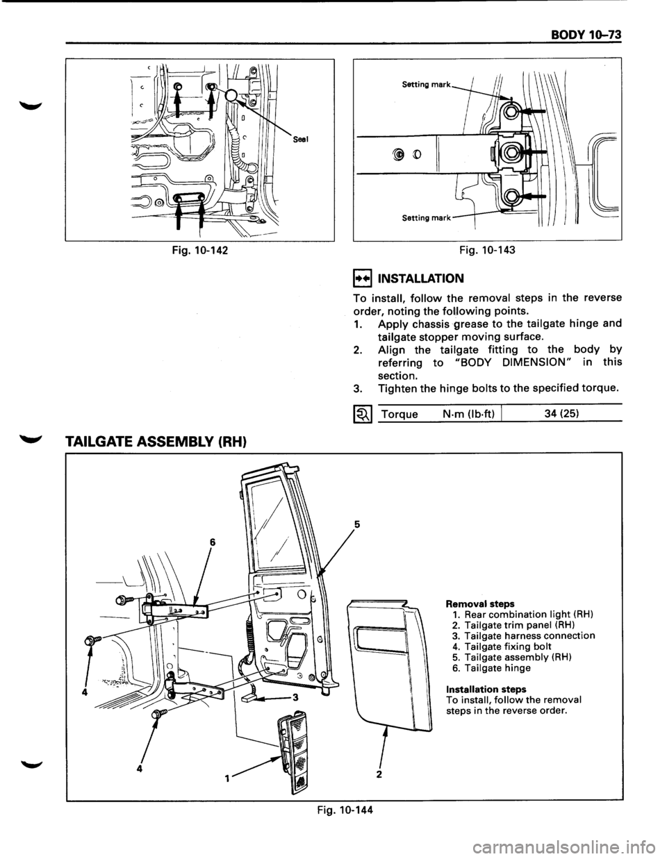
Saal
Fig. 10-142
~ TAILGATE ASSEMBLY (RH)
4
1
BODY 10-73
Setting mark
Setting mark
Fig. 10-143
I••IINSTALLATION
To install, follow the removal steps in the reverse
order,
noting the fol!lowing points.
1. Apply chassis grease to the tailgate hinge and
tailgate stopper
moving surface.
2. Align the tailgate fitting to the body by
referring to "BODY DIMENSION" in this
section.
3. Tighten the hinge bolts to the specified torque.
~~~ Torque
5
I
2
Fig. 10-144
N·m (lb·ftl J 34 (25)
Removal steps 1. Rear combination light (RH) 2. Tailgate trim panel (RH)
3. Tailgate harness connection 4. Tailgate fixing bolt 5. Tailgate assembly (RH)
6. Tailgate hinge
Installation steps To install, follow the removal steps in the reverse order.
Page 1832 of 1928
10-74 BODY
1++1 REMOVAL
Preparation: Disconnect the battery ground cable
1. Rear combination light (RH)
2. Tailgate trim panel (RH)
• Refer to "TAILGATE TRIM PANEL (RH)" in
this section.
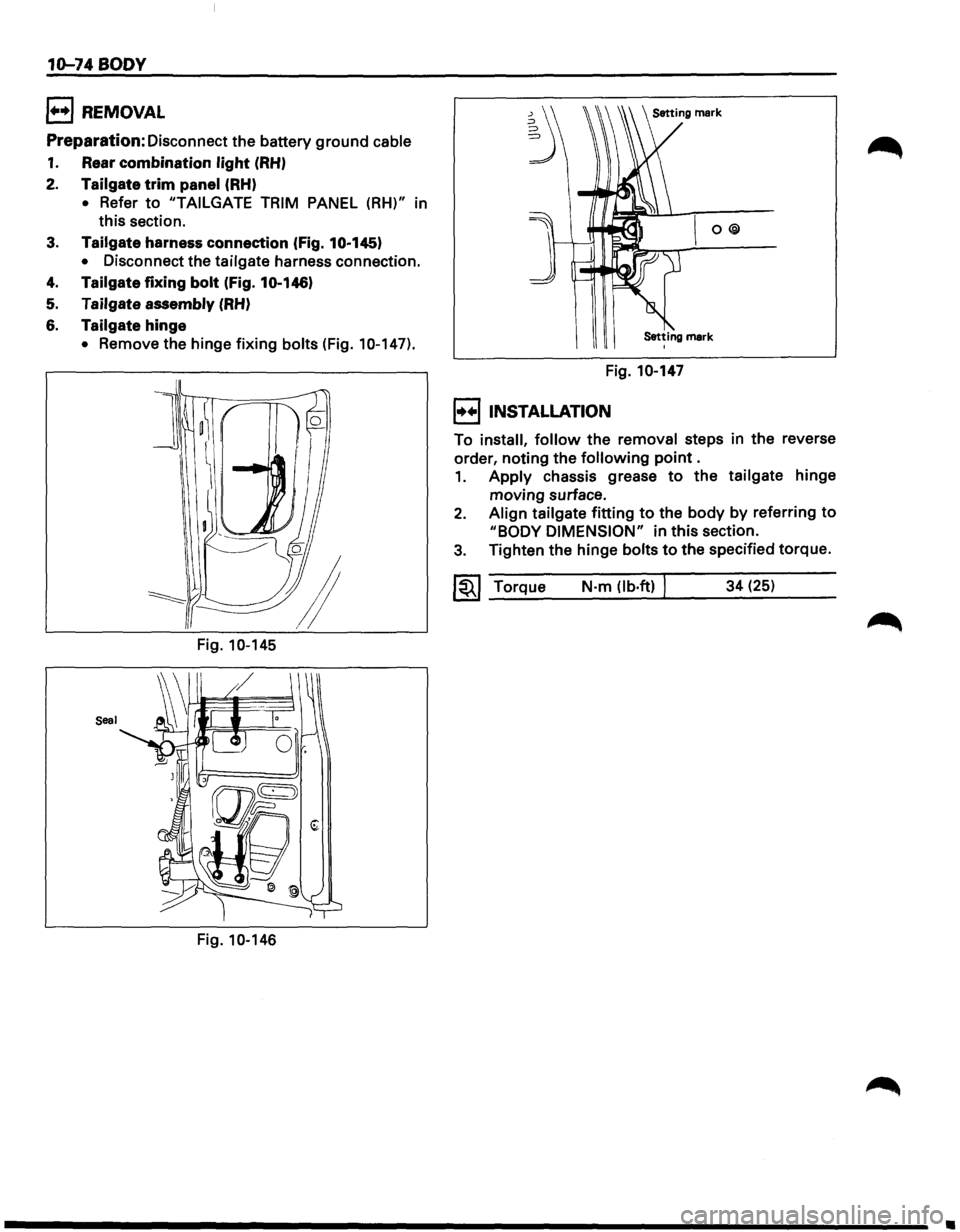
3. Tailgate harness connection (Fig. 10·145)
• Disconnect the tailgate harness connection.
4. Tailgate fixing bolt (Fig. 10.146)
5. Tailgate assembly (RH)
6. Tailgate hinge
• Remove the hinge fixing bolts (Fig. 10-147).
Fig.
10-145
Seal
Fig. 10-146
~ O@
Setting mark I
Fig. 10-147
I••IINSTALLATION
To install, follow the removal steps in the reverse
order, noting the
following point .
1. Apply chassis grease to the tailgate hinge
moving surface.
2. Align tailgate fitting to the body by referring to
"BODY DIMENSION" in this section.
3. Tighten the hinge bolts to the specified torque.
~~~ Torque N·m (lb·ft) I 34 (25)
•
Page 1833 of 1928
TAILGATE STRIKERS
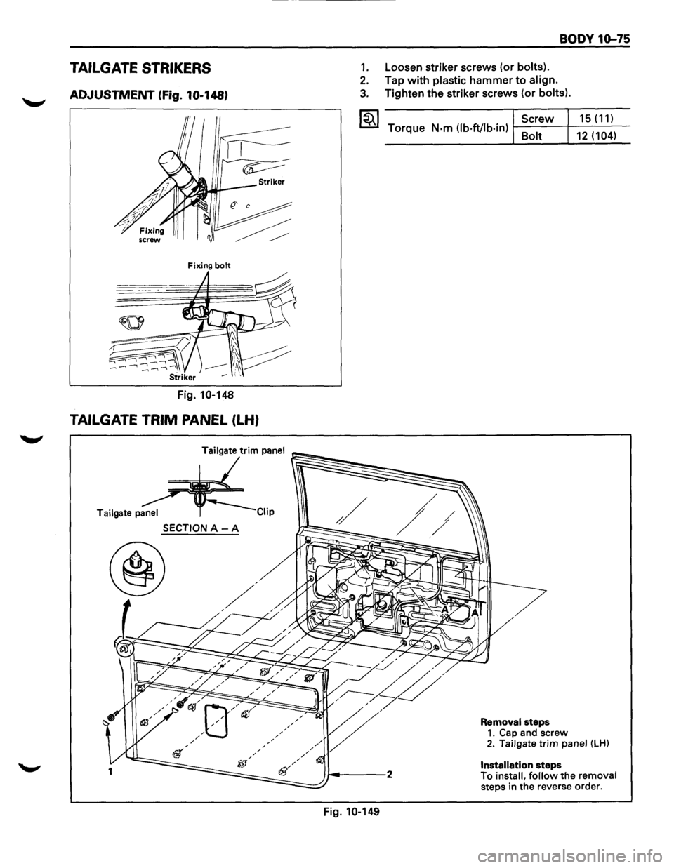
ADJUSTMENT (fig. 10-148)
Fixing bolt
Fig. 10-148
TAILGATE TRIM PANEL (LH)
Tailgate panel ip
SECTION A -A
1
BODY 10-75
1. Loosen striker screws (or bolts).
2. Tap with plastic hammer to align.
3. Tighten the striker screws (or bolts).
~~~ Screw 15 (11) Torque N-m (lb·ft/lb-in) f--8-0 -1t--+-1
-2-(-'-1 -
04-)-
Fig. 10-149
Removal steps 1. Cap and screw 2. Tailgate trim panel (LH)
Installation steps
To install, follow the removal steps in the reverse order.
Page 1834 of 1928
10-76 BODY
1+•1 REMOVAL
Preparation: Disconnect the battery ground cable
1. Cap and screw
2. Tailgate trim panel (LH)
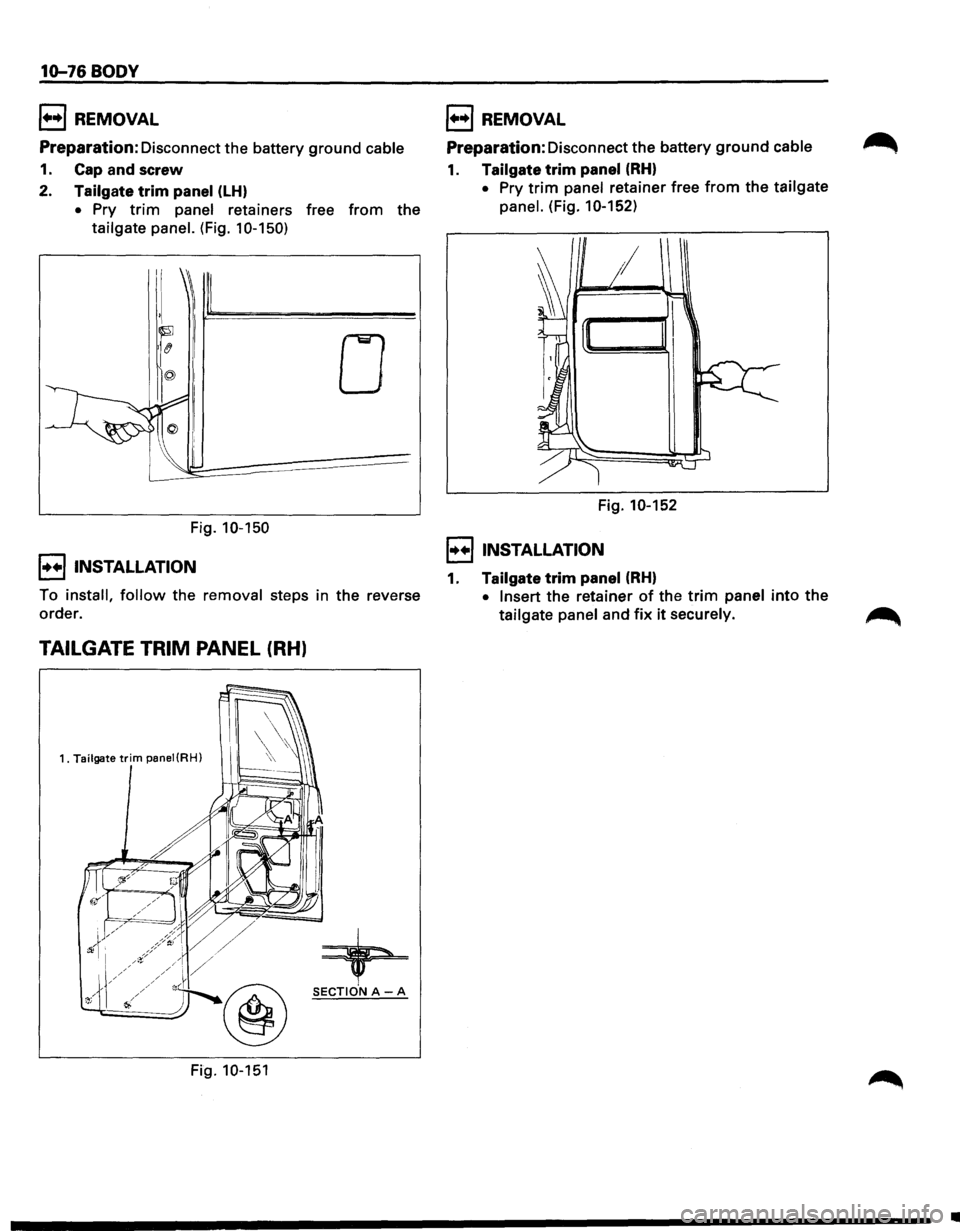
• Pry trim panel retainers free from the
tailgate panel. (Fig. 1 0-150)
Fig. 10-150
!••I INSTALLATION
0
To install, follow the removal steps in the reverse
order.
TAILGATE TRIM PANEL (RH)
1. Tailgate trim panei(RH)
+ @ SECTIONA-A
Fig. 10-151
1++1 REMOVAL
Preparation: Disconnect the battery ground cable
1. Tailgate trim panel (RH)
• Pry trim panel retainer free from the tailgate
panel.
(Fig. 10-152)
Fig. 10-152
!••I INSTALLATION
1. Tailgate trim panel (RH)
• Insert the retainer of the trim panel into the
tailgate panel and fix it securely.
•
Page 1835 of 1928
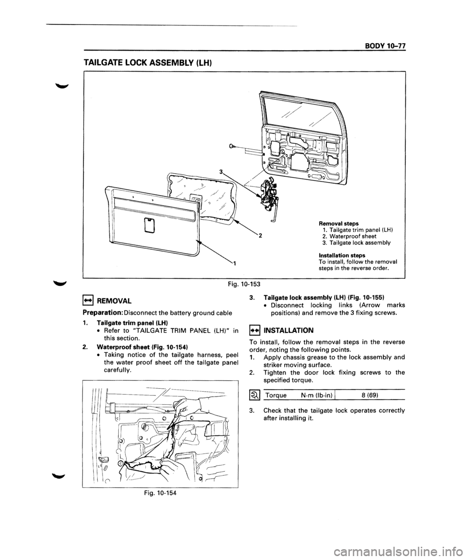
TAILGATE LOCK ASSEMBLY (LH)
1
BODY 10-77
Removal steps 1. Tailgate trim panel (LH) 2. Waterproof sheet
3. Tailgate lock assembly
Installation steps To install, follow the removal
steps in the reverse order.
Fig. 10-153
E) REMOVAL
Preparation: Disconnect the battery ground cable
1. Tailgate trim panel (LH)
• Refer to "TAILGATE TRIM PANEL (LH)" in
this section.
2. Waterproof sheet (Fig. 10-154)
•
Taking notice of the tailgate harness, peel
the water
proof sheet off the tailgate panel
carefully.
Fig. 10-154
3. Tailgate lock assembly {LH) (Fig. 10-155)
•
Disconnect locking links (Arrow marks
positions) and remove the
3 fixing screws.
l••liNSTALLATION
To install, follow the removal steps in the reverse
order, noting the
following points.
1. Apply chassis grease to the lock assembly and
striker
moving surface.
2. Tighten the door lock fixing screws to the
specified torque.
~~~ Torque N·m (lb·in) I 8 (69)
3. Check that the tailgate lock operates correctly
after
installing it.
j
j
j
j
j
j
j
j
j
j
j
j
j
j
j
j
j
j
j
j
j j
j
j
j
j
j
j
j
j
j
j
j
j
j
j
j
j
j
j
j
j
j
j
j j
j
j
j
j
j
j
j
j
j
j
j
j
j
j
j
j
j j
j
j j j
j
j
Page 1836 of 1928
10-78 BODY
To actuator
To inside lock knob I
l
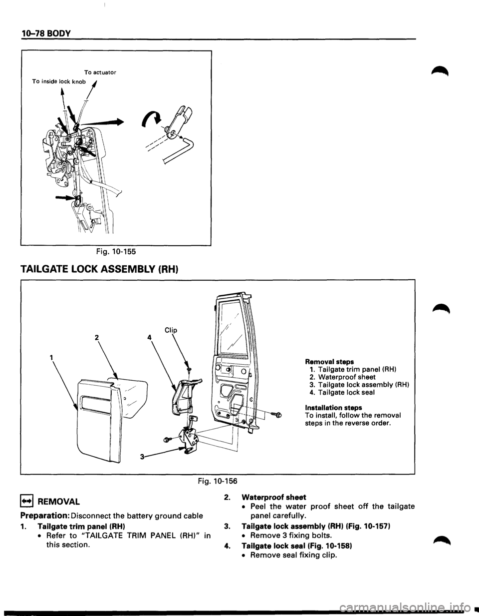
Fig. 10-155
TAILGATE LOCK ASSEMBLY (RH)
2
Removal steps 1. Tailgate trim panel (RH) 2. Waterproof sheet 3. Tailgate lock assembly (RH)
4. Tailgate lock seal
Installation steps
To install, follow the removal
steps in
the reverse order.
Fig. 10-156
1••1 REMOVAL
Preparation: Disconnect the battery ground cable
1. Tailgate trim panel (RH)
• Refer to "TAILGATE TRIM PANEL (RH)" in
this section. 2.
Waterproof sheet
• Peel
the water proof sheet off the tailgate
panel carefully.
3. Tailgate lock assembly (RH) (fig. 10-157)
•
Remove 3 fixing bolts.
4. Tailgate lock seal (fig. 10-158)
•
Remove seal fixing clip.
•
Page 1837 of 1928
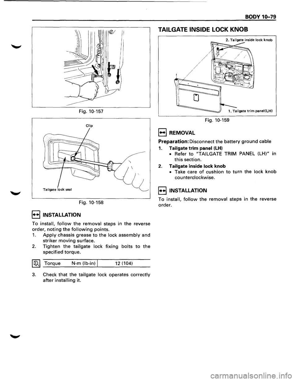
Fig. 10-157
Clip
Tailgate lock seal
Fig. 10-158
I••! INSTALLATION
')
To install, follow the removal steps in the reverse
order,
noting the following points.
1. Apply chassis grease to the lock assembly and
striker
moving surface.
2. Tighten the tailgate lock fixing bolts to the
specified torque.
~~~ Torque N·m (lb·in) I 12 (104)
3. Check that the tailgate lock operates correctly
after installing it.
BODY 10-79
TAILGATE INSIDE LOCK KNOB
2. Tailgate inside lock knob
Fig. 10-159
1•+1 REMOVAL
Preparation: Disconnect the battery ground cable
1. Tailgate trim panel (LH)
• Refer to "TAIL GATE TRIM PANEL (LH)" in
this section.
2. Tailgate inside lock knob
• Take care of cushion to turn the lock knob
counterclockwise.
I••IINSTALLATION
To install, follow the removal steps in the reverse
order.
Page 1838 of 1928
10-80 BODY
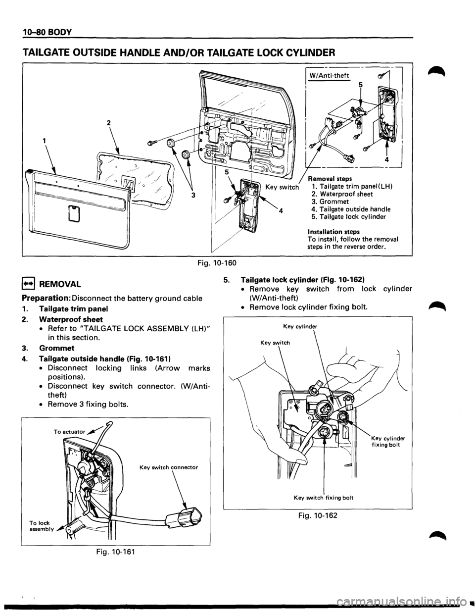
TAILGATE OUTSIDE HANDLE AND/OR TAILGATE LOCK CYLINDER
1
Fig. 10-160
I W/A~ti-theft
I
Removal steps
1. Tailgate trim panei(LH)
2. Waterproof sheet
3. Grommet
4.
Tailgate outside handle 5. Tailgate lock cylinder
Installation steps
To install, follow the removal
steps in the reverse order.
1••1 REMOVAL 5. Tailgate lock cylinder (fig. 10-162)
Preparation: Disconnect the battery ground cable
1. Tailgate trim panel
2. Waterproof sheet
• Refer to "TAILGATE LOCK ASSEMBLY (LH)"
in
this section.
3. Grommet
4. Tailgate outside handle (Fig. 10-161)
•
Disconnect locking links (Arrow marks
positions).
• Disconnect key switch connector. (W/Anti
theft)
• Remove 3 fixing bolts.
To lock assembly
Fig. 10-161
• Remove key switch from lock cylinder
(W/Anti-theft)
• Remove lock cylinder fixing bolt.
Key cylinder
Key switch fixing bolt
Fig. 10-162
Key cylinder fixing bolt
..
Page 1839 of 1928
I••IINSTALLATION
To install, follow the removal steps in the reverse
order,
noting the following points.
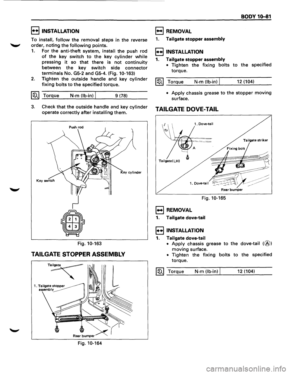
1. For the anti-theft system, install the push rod
of the key switch to the key cylinder while
pressing it so that there is not continuity
between the key switch side connector
terminals No. GS-2 and GS-4. (Fig. 10-163)
2. Tighten the outside handle and key cylinder
fixing bolts to the specified torque.
~~~ Torque N·m (lb·in) I 9 (78)
B REMOVAL
1. Tailgate stopper assembly
I••! INSTALLATION
1. Tailgate stopper assembly
• Tighten the fixing bolts
torque.
~~~ Torque N·m (lb·in) I
BODY 10-81
to the specified
12 (104)
•
Apply chassis grease to the stopper moving
surface.
3. Check that the outside handle and key cylinder TAILGATE DOVE-TAIL
operate correctly after installing them.
Fig.
10-163
TAILGATE STOPPER ASSEMBLY
T~
Fig. 10-164
1. Dove-tail
Tailgate
striker
Tailgate( LH)
1. Dove-tail
Fig. 10-165
1••1 REMOVAL
1. Tailgate dove-tail
I••IINSTALLATION
1. Tailgate dove-tail
• Apply chassis grease to the dove-tail (@)
moving surface.
• Tighten the fixing bolts to the specified
torque.
~~~ Torque N·m Ob·in) I 12 (104)
Page 1840 of 1928
10-82 BODY
TAILGATE DOVE-TAIL STRIKER
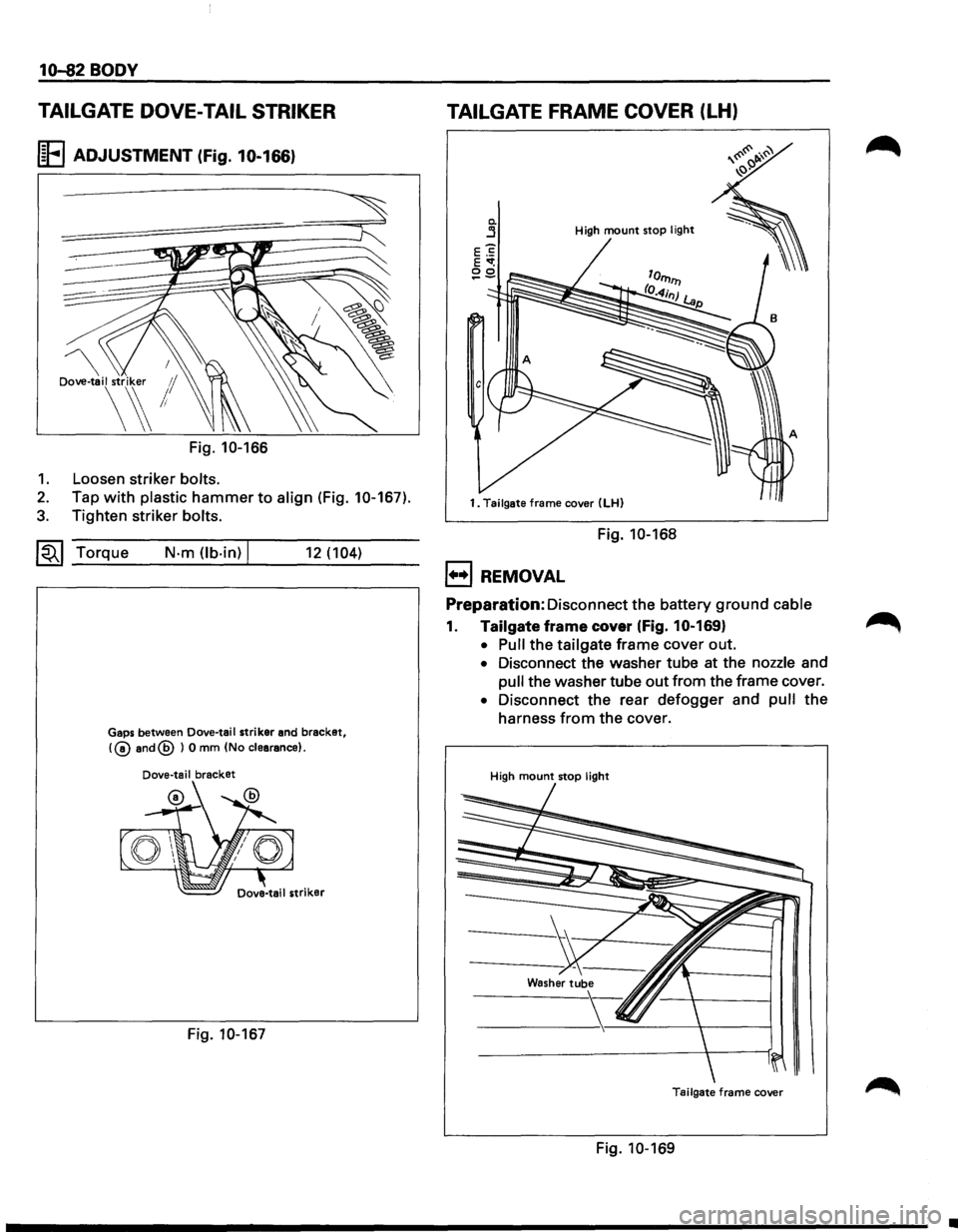
I~FI ADJUSTMENT (Fig. 10-166)
Dove-tail striker 1/
\~!
Fig. 10-166
1. Loosen striker bolts.
2. Tap with plastic hammer to align (Fig. 10-167).
3. Tighten striker bolts.
~~~ Torque N·m (lb.in) I 12 (104)
Gaps between Dove-tail striker and bracket,
!@and@ ) 0 mm (No clearance).
Dove-tail bracket
Fig. 10-167
TAILGATE FRAME COVER (LH)
0. j High mount stop light
1. Tailgate frame cover (LH)
Fig. 10-168
1+•1 REMOVAL
Preparation:
Disconnect the battery ground cable
1. Tailgate frame cover (Fig. 10-169}
• Pull the tailgate frame cover out.
• Disconnect the washer tube at the nozzle and
pull the washer tube out from the frame cover.
• Disconnect the rear defogger and pull the
harness
from the cover.
High mount stop light
Tailgate frame cover
Fig. 10-169
•