instrument panel ISUZU TROOPER 1995 User Guide
[x] Cancel search | Manufacturer: ISUZU, Model Year: 1995, Model line: TROOPER, Model: ISUZU TROOPER 1995Pages: 1928
Page 335 of 1928
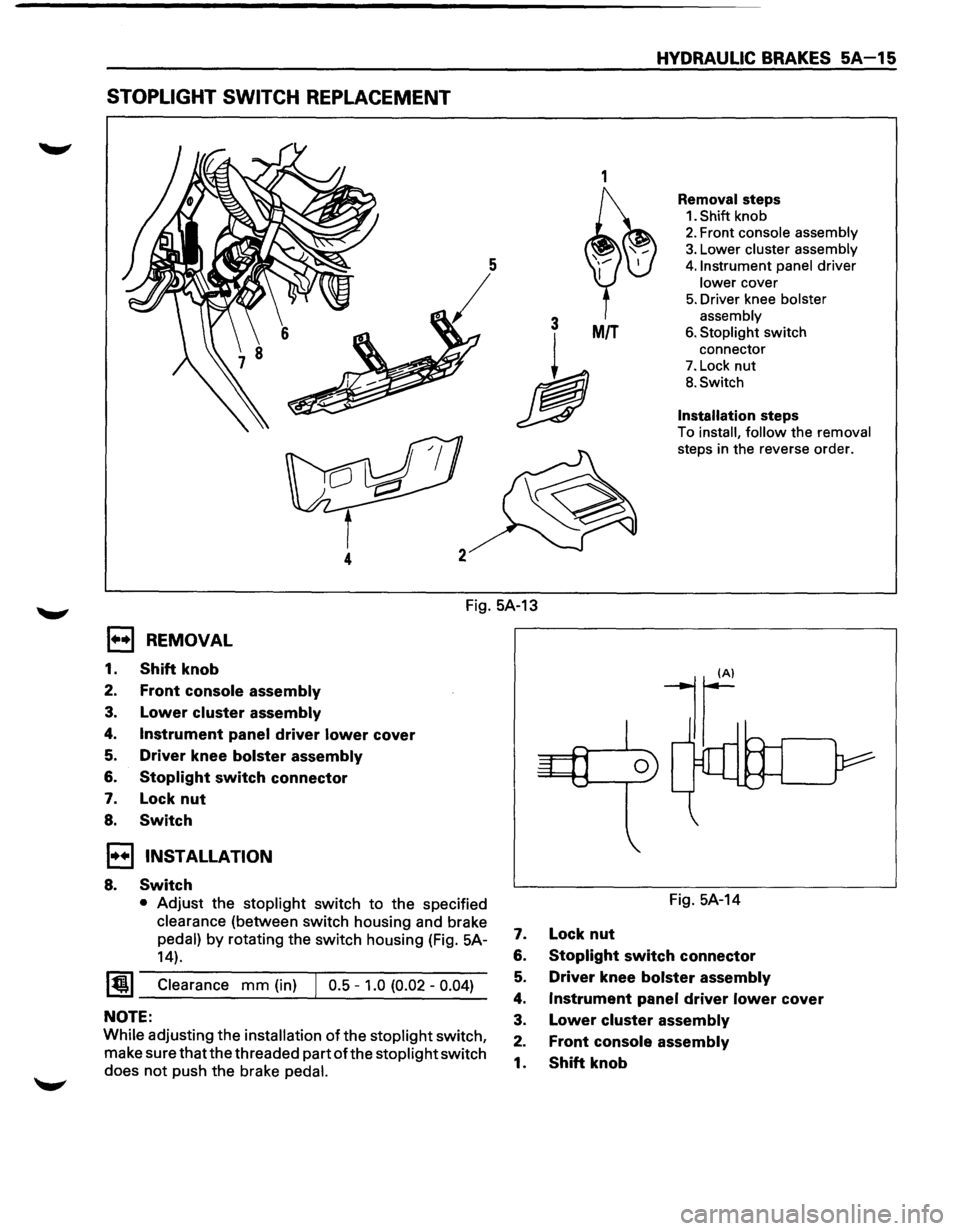
STOPLIGHT SWITCH REPLACEMENT
1
3 MIT
h
4
HYDRAULIC BRAKES SA-15
Removal steps
1. Shift knob
2. Front console assembly
3. Lower cluster assembly
4. Instrument panel driver
lower cover
5. Driver knee bolster
assembly
6. Stoplight switch
connector
7. Lock nut
B. Switch
Installation steps
To install, follow the removal
steps in the reverse order.
Fig. 5A-13
1••1 REMOVAL
1. Shift knob
2. Front console assembly
3. Lower cluster assembly
4. Instrument panel driver lower cover
5. Driver knee bolster assembly
6. Stoplight switch connector
7. Lock nut
8. Switch
1••1 INSTALLATION
8. Switch
• Adjust the stoplight switch to the specified
clearance (between switch housing and brake
pedal) by rotating the switch housing (Fig. 5A-
14).
~~~ Clearance mm (in) J 0.5 -1.0 (0.02 -0.04)
NOTE:
While adjusting the installation of the stoplight switch,
make sure that the threaded part
ofthe stoplight switch
does
not push the brake pedal.
Fig. 5A-14
7. Lock nut
6. Stoplight switch connector
5. Driver knee bolster assembly
4. Instrument panel driver lower cover
3. Lower cluster assembly
2. Front console assembly
1. Shift knob
Page 373 of 1928
REAR WHEEL ANTILOCK BRAKE SYSTEM 5A3-5
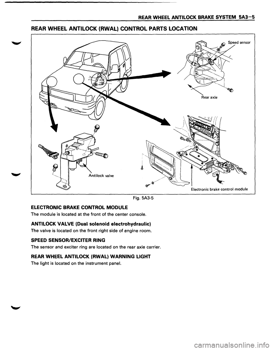
REAR WHEEL ANTILOCK (RWAL} CONTROL PARTS LOCATION
Fig. 5A3-5
ELECTRONIC BRAKE CONTROL MODULE
The module is located at the front of the center console.
ANTILOCK VALVE (Dual solenoid electrohydraulic)
The valve is located on the front right side of engine room.
SPEED SENSOR/EXCITER RING
The sensor and exciter ring are located on the rear axle carrier.
REAR WHEEL ANTILOCK (RWAL) WARNING LIGHT
The light is located on the instrument panel.
Rear axle
Electronic
brake control module
Page 374 of 1928
5A3-6 REAR WHEEL ANTILOCK BRAKE SYSTEM
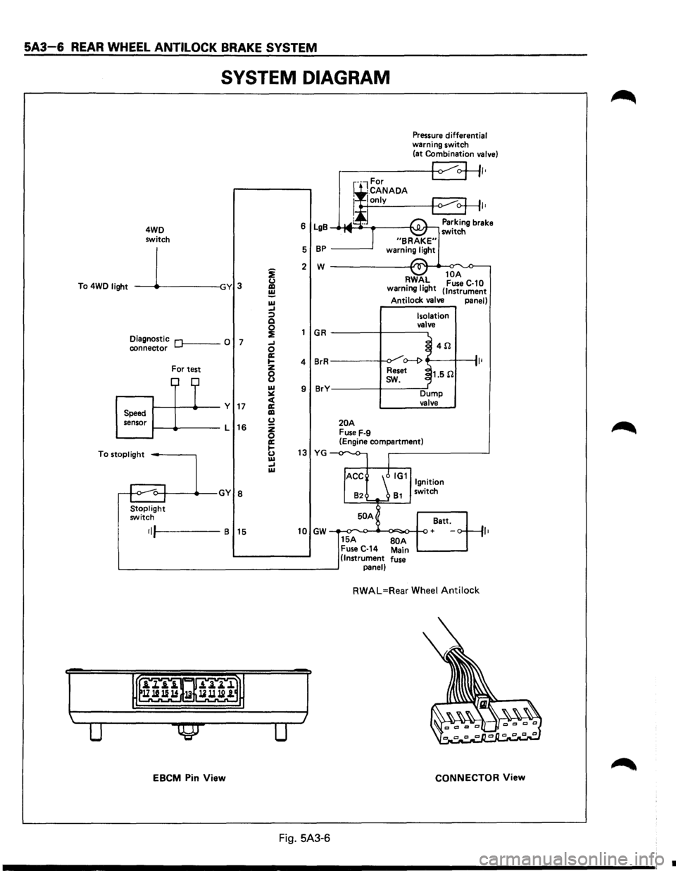
SYSTEM DIAGRAM
4WD
switch
To 4WD
light -----11~-----lGY 3
Diagnostic Of------0 7 connector
For test
1-----11---+--y 17 Speed
sensor 1-----lt-----L
16
To
stoplight -----,
Stoplight switch
•IJI-----B 15
EBCM Pin View
i
&l ~ IU _, :;) Q
~ _, 0 a: .... z
8 IU ~ c( a: liD (.) z 0 a: 1-(.) IU _, IU
Pressure differential warning switch
(at Combination valve)
r-----+-<1 ~+II•
I•
6 LgB Parking brake _.-MI ____ ___,I'\.JI.Jr-, switch
5
BP -----'
2 w ------------~~._~
GR
4 BrR
9 BrY
20A Fuse F-9
RWAL 10
A •
1• h Fuse C-10
warnmg IQ t (Instrument
Antilock valve panel)
Isolation
valve
~ 4il .J o--1> ~
Reset ~1.5il
I
sw.
Dump valve
(Engine compartment)
13 YG -
82 81 switch
50 A
Batt.
10 GW + ,,
15A BOA Fuse C-14 Main (Instrument fuse panel)
RWAL=Rear Wheel Antilock
CONNECTOR View
Fig. 5A3-6
•
Page 378 of 1928
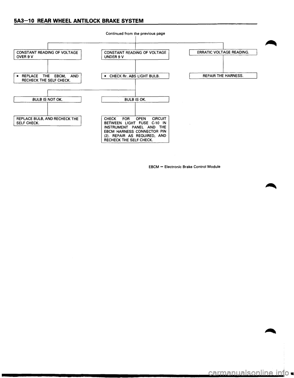
5A3-1 0 REAR WHEEL ANTI LOCK BRAKE SYSTEM
Continued from the previous page
I
I
I CONSTANT READING OF VOLTAGE J CONSTANT READING OF VOLTAGE I ERRATIC VOLTAGE READING. I OVER 9 V
UNDER 9 V
I ,. REPLACE THE EBCM, AND I • CHECK Rr. ABS LIGHT BULB. I REPAIR THE HARNESS. I RECHECK THE SELF CHECK.
I
I BULB IS NOT OK. I BULB IS OK.
1 I REPLACE BULB, AND RECHECK THE J CHECK FOR OPEN CIRCUIT
SELF CHECK. BETWEEN LIGHT FUSE C-10 IN INSTRUMENT PANEL AND THE EBCM HARNESS CONNECTOR PIN (2). REPAIR AS REQUIRED, AND RECHECK THE SELF CHECK.
EBCM
-Electronic Brake Control Module
•
Page 382 of 1928
5A3-14 REAR WHEEL ANTILOCK BRAKE SYSTEM
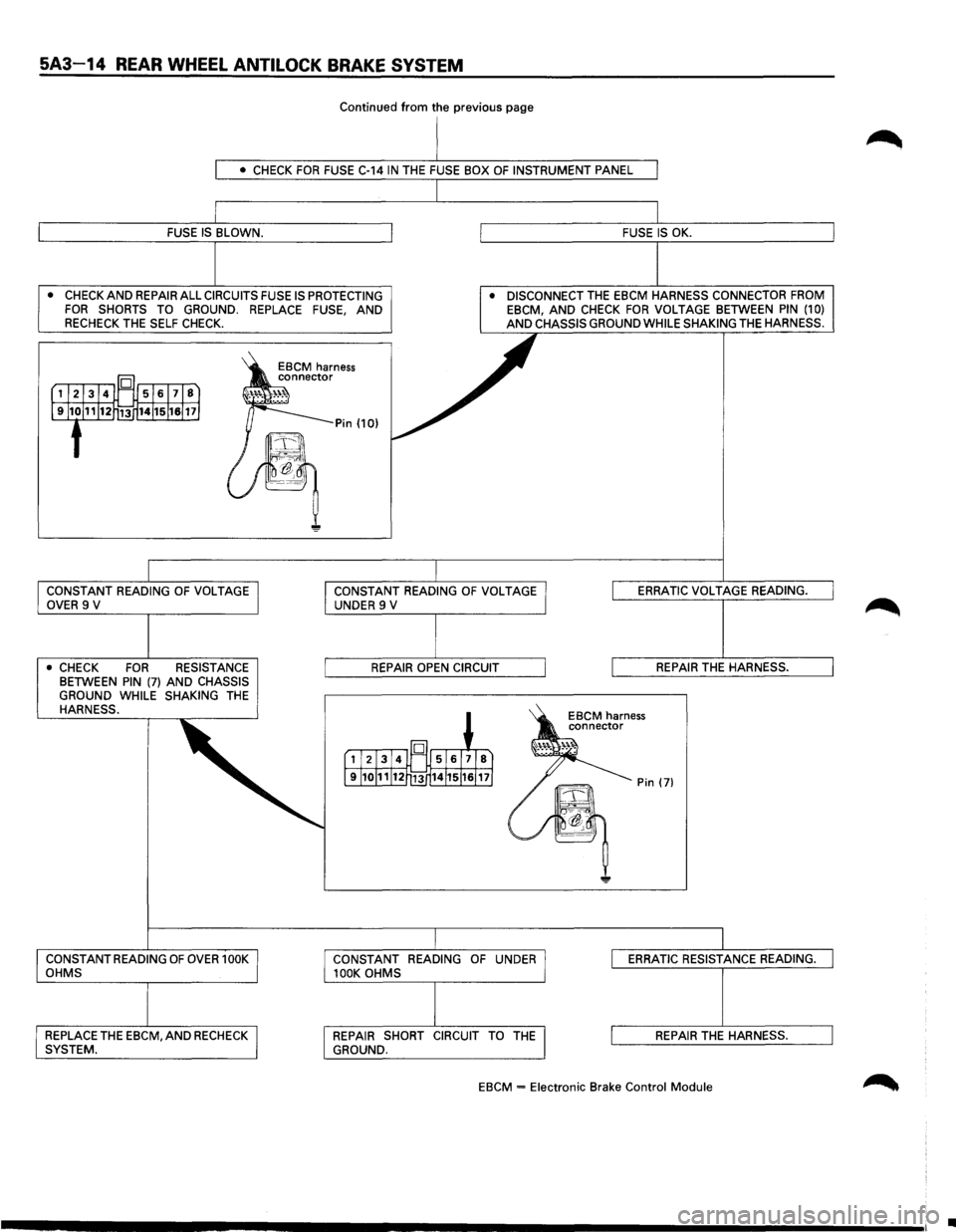
Continued from the previous page
• CHECK FOR FUSE C-14 IN THE FUSE BOX OF INSTRUMENT PANEL
FUSE IS BLOWN. FUSE IS OK.
•
CHECK AND REPAIR ALL CIRCUITS FUSE IS PROTECTING FOR SHORTS TO GROUND. REPLACE FUSE, AND RECHECK THE SELF CHECK.
• DISCONNECT THE EBCM HARNESS CONNECTOR FROM EBCM, AND CHECK FOR VOLT AGE BETWEEN PIN (1 0) AND CHASSIS GROUND WHILE SHAKING THE HARNESS.
CONSTANT READING
OF VOLTAGE OVER 9 V
• CHECK FOR RESISTANCE BETWEEN PIN (7) AND CHASSIS
GROUND WHILE SHAKING THE HARNESS.
CONSTANT READING
OF OVER 1 OOK OHMS
REPLACE THE EBCM, AND RECHECK SYSTEM. CONSTANT
READING
OF VOLTAGE UNDER 9 V
REPAIR OPEN CIRCUIT
CONSTANT
READING OF UNDER 100K OHMS
REPAIR SHORT CIRCUIT TO
THE GROUND. ERRATIC
VOLTAGE
READING.
REPAIR THE HARNESS.
ERRATIC RESISTANCE READING.
REPAIR
THE HARNESS.
EBCM = Electronic Brake Control Module
•
Page 414 of 1928
5A4-4 4-WHEEL ANTILOCK BRAKE SYSTEM (ABS)
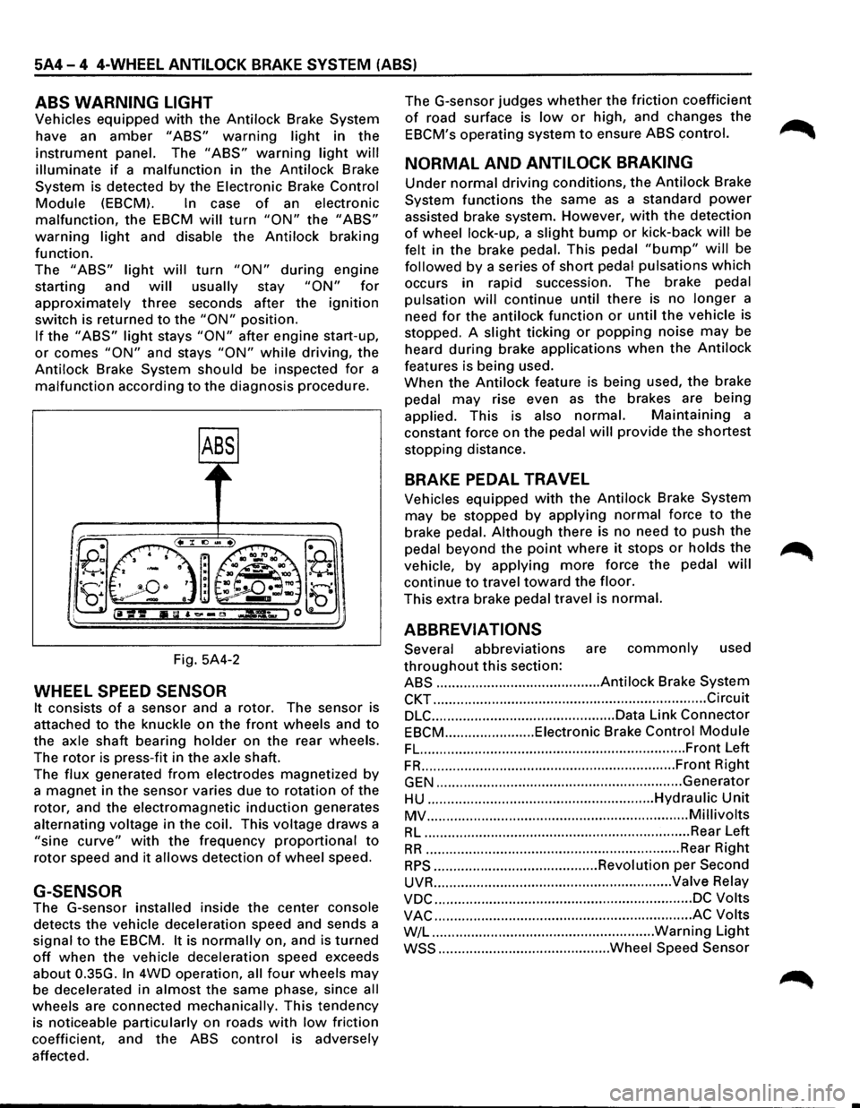
ABS WARNING LIGHT
Vehicles equipped with the Antilock Brake System
have an
amber "ABS" warning light in the
instrument panel. The "ABS" warning light will
illuminate if a malfunction in the Antilock Brake
System is detected by the Electronic Brake
Control
Module (EBCM). In case of an electronic
malfunction, the EBCM will turn "ON" the "ABS"
warning light and disable the Antilock braking
function.
The
"ABS" light will turn "ON" during engine
starting and
will usually stay "ON" for
approximately three seconds after the ignition
switch is returned to the "ON" position.
If the "ABS" light stays "ON" after engine start-up,
or comes "ON" and stays "ON" while driving, the
Antilock Brake System should be inspected
for a
malfunction according to the diagnosis procedure.
Fig. 5A4-2
WHEEL SPEED SENSOR
It consists of a sensor and a rotor. The sensor is
attached
to the knuckle on the front wheels and to
the axle shaft bearing holder on the rear wheels.
The
rotor is press-fit in the axle shaft.
The
flux generated from electrodes magnetized by
a magnet in the sensor varies due to rotation of the
rotor, and the electromagnetic
induction generates
alternating voltage in
the coil. This voltage draws a
"sine curve" with the frequency proportional to
rotor speed and it allows detection of wheel speed.
G-SENSOR
The G-sensor installed inside the center console
detects the vehicle deceleration speed and sends a
signal
to the EBCM. It is normally on, and is turned
off when the vehicle deceleration speed exceeds
about 0.35G.
In 4WD operation, all four wheels may
be decelerated in almost the same phase, since all
wheels are connected mechanically. This tendency
is noticeable particularly on roads
with low friction
coefficient, and the
ABS control is adversely
affected. The
G-sensor judges
whether the friction coefficient
of road surface is low or high, and changes the
EBCM's operating system to ensure ABS control.
NORMAL AND ANTILOCK BRAKING
Under normal driving conditions, the Antilock Brake
System functions the same
as a standard power
assisted brake system. However, with the detection
of wheel lock-up, a slight bump or kick-back will be
felt in the brake pedal. This pedal
"bump" will be
followed by a series of short pedal pulsations which
occurs in rapid succession. The brake pedal
pulsation
will continue until there is no longer a
need
for the antilock function or until the vehicle is
stopped. A
slight ticking or popping noise may be
heard
during brake applications when the Antilock
features is being used.
When the
Antilock feature is being used, the brake
pedal
may rise even as the brakes are being
applied. This is also
normal. Maintaining a
constant force on the pedal
will provide the shortest
stopping distance.
BRAKE PEDAL TRAVEL
Vehicles equipped with the Antilock Brake System
may be stopped by applying normal force to the
brake pedal.
Although there is no need to push the
pedal beyond the
point where it stops or holds the ~
vehicle, by applying more force the pedal will
continue to travel toward the floor.
This extra brake pedal travel is normal.
ABBREVIATIONS
Several abbreviations are commonly used
throughout this section:
ABS .......................................... Antilock Brake System
CKT ...................................................................... Circuit
DLC ............................................... Data Link Connector
EBCM ....................... Eiectronic Brake Control Module
FL. ................................................................... Front Left
FR ................................................................. Front Right
GEN ............................................................... Generator
HU .......................................................... Hydraulic Unit
MV ................................................................... Millivolts
RL .................................................................... Rear Left
RR ................................................................. Rear Right
RPS .......................................... Revolution per Second
UVR ............................................................. Valve Relay
VDC .................................................................. DC Volts
VAC .................................................................. AC Volts
W/L .........................................................
Warning Light
WSS ............................................ Wheel Speed Sensor
Page 700 of 1928
6E2-4 DRIVEABILITY AND EMISSIONS
BASIC KNOWLEDGE REQUIRED
Before using this section of the Service Manual,
there are some areas that you should be familiar
with. Without this basic knowledge, you will have
trouble using the diagnostic procedures
contained in this section.
BASIC ELECTRIC CIRCUITS
You should understand the basic theory of
electricity, and know the meaning of voltage,
amps, and ohms. You should understand what
happens in a circuit with an open or a shorted
wire. You
should be able to read and understand a
wiring diagram. A shortto ground is referred to as
a ground to distinguish it from a short between
wires.
USE OF CIRCUIT TESTING TOOLS
You should know how to use a test light, how to
connect and use a tachometer, and
how to use
jumper wires to by-pass components to test
circuits. Care
should be taken to not deform the
terminal when testing.
USE OF DIGITAL VOLT-OHM METER
(DVOM)
You should be familiar with the Digital Volt-Ohm
Meter, particularly special tool J-39200 or
equivalent. You should be able to measure
voltage, resistance, and current and know how to
use the meter correctly.
The
Digital Volt-Ohm Meter is covered in the
"Special Tools" portion of this section.
DIAGNOSTIC INFORMATION
The diagnostic "Trouble Tree" charts and func
tional checks in this manual are designed to locate
a faulty circuit or component through logic based
on the process
of elimination. The charts are
prepared
with the requirement that the vehicle
functioned correctly at the time of assembly and
that there are no multiple failures.
The Engine Control Module (ECM) performs a
continual self-diagnosis on certain control
functions. This diagnostic capability is
complemented by the diagnostic procedures
contained in this
manual. The ECM's language for
communicating the source of a malfunction is a
system
of Diagnostic Trouble Codes (DTCs). The
DTC(s) are
two or three digit numbers that can
range from12 to
51. When a malfunction is
detected by the ECM, a DTC is set and the
Malfunction Indicator Lamp is illuminated.
"CHECK ENGINE" MALFUNCTION
INDICATOR
LAMP (MIL)
This light is on the instrument panel and has two
functions:
• It is used to tell the driver that a problem has
occurred, and that the
vehicle should be
taken
for service as soon as reasonably
possible.
• It
is used by the technician to read out
'Trouble Codes" to help diagnose system
problems.
As a bulb and system check, the light will come
"ON" with the key "ON" and the engine not
running. When the engine is started, the light will
turn off. If the light remains on, the self-diagnostic
system has detected a
problem. If the problem
goes away, the light will go out in most cases after
10 seconds, but a Trouble Code will remain stored
in the
ECM.
When the light remains "ON" while the engine is
running,
or when a malfunction is suspected due
to a
driveability or emissions problem, a on-board
diagnostic system check
must be performed. The
procedures
for these checks are given in Section
"A". These checks will expose malfunctions
which may
not be detected if other diagnostics
are performed
prematurely.
INTERMITTENT "CHECK ENGINE"
MALFUNCTION INDICATOR
LAMP (MIL)
In the case of an "intermittent" problem, the
"Check Engine"
malfunction indicator lamp will
light
for ten (1 0) seconds and then will go out.
However, the corresponding
trouble code will be
stored in the
memory of the ECM until the battery
positive
voltage to the ECM has been removed.
When unexpected DTC(s) appear during the
DTC
code reading process, one can assume that these
DTC(s) were set by an intermittent malfunction
and could be helpful in diagnosing the system.
An intermittent
DTC may or may not re-set. If it is
an intermittent failure, a DTC Chart is not used.
Consult the "Diagnostic Aids" on the intermittent
trouble code. Section "B" also covers the topic of
"intermittents". A physical inspection of the
applicable sub-system most often will resolve the
problem.
II
Page 701 of 1928
......, .., LU
READING DIAGNOSTIC TROUBLE CODES
(Fig. 6E2-1)
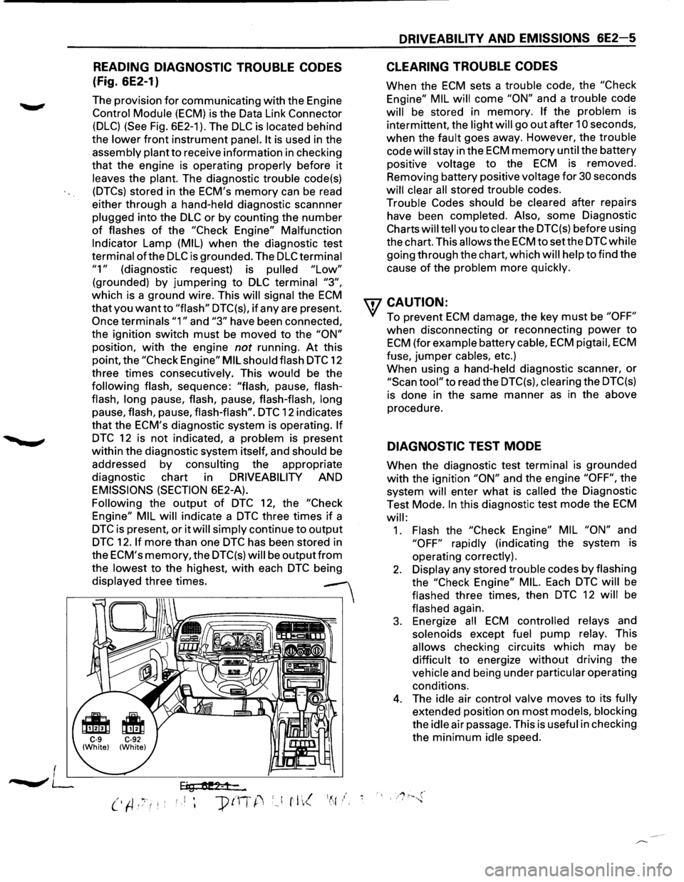
The provision for communicating with the Engine
Control Module (ECM) is the Data Link Connector
(DLC) (See Fig. 6E2-1 ). The DLC is located behind
the
lower front instrument panel. It is used in the
assembly plant
to receive information in checking
that the engine is operating properly before it
leaves the plant. The diagnostic trouble code(s)
(DTCs) stored in the ECM's memory can be read
either through a hand-held diagnostic scannner
plugged into the
DLC or by counting the number
of flashes of the "Check Engine" Malfunction
Indicator Lamp (MIL) when the diagnostic test
terminal
ofthe DLC is grounded. The DLC terminal
"1" (diagnostic request) is pulled "Low"
(grounded) by jumpering to DLC terminal "3",
which is a ground wire. This will signal the ECM
that you want to "flash" DTC(s), if any are present.
Once terminals "1" and "3" have been connected,
the ignition switch
must be moved to the "ON"
position, with the engine not running. At this
point, the
"Check Engine" MIL should flash DTC 12
three times consecutively. This
would be the
following flash, sequence: "flash, pause, flash
flash,
long pause, flash, pause, flash-flash, long
pause, flash, pause, flash-flash". DTC 12 indicates
that the ECM's diagnostic system is operating.
If
DTC 12 is not indicated, a problem is present
within the diagnostic system itself, and should be
addressed
by consulting the appropriate
diagnostic chart in
DRIVEABILITY AND
EMISSIONS (SECTION 6E2-A).
Following the output of DTC 12, the "Check
Engine" MIL
will indicate a DTC three times if a
DTC is present, or it will simply continue to output
DTC 12. If more than one DTC has been stored in
the
ECM's memory, the DTC(s) will be outputfrom
the lowest to the highest, with each DTC being
displayed three times.
--
Eig tU!2-1-...
DRIVEABILITY AND EMISSIONS 6E2-5
CLEARING TROUBLE CODES
When the ECM sets a trouble code, the "Check
Engine" MIL
will come "ON" and a trouble code
will be stored in memory. If the problem is
intermittent, the light
will go out after 10 seconds,
when the fault goes away. However, the trouble
code
will stay in the ECM memory until the battery
positive voltage
to the ECM is removed.
Removing battery positive voltage
for 30 seconds
will clear all stored trouble codes.
Trouble
Codes should be cleared after repairs
have been completed. Also, some Diagnostic
Charts will tell you to clear the DTC(s) before using
the chart. This
allows the ECM tosetthe DTCwhile
going through the chart, which will help to find the
cause
of the problem more quickly.
wcAUTION:
• To prevent ECM damage, the key must be "OFF"
when disconnecting or reconnecting power to
ECM (for example battery cable, ECM pigtail, ECM
fuse, jumper cables, etc.)
When using a hand-held diagnostic scanner,
or
"Scan tool" to read the DTC(s), clearing the DTC(s)
is done in the same manner as in the above
procedure.
DIAGNOSTIC TEST MODE
When the diagnostic test terminal is grounded
with the ignition "ON" and the engine "OFF", the
system
will enter what is called the Diagnostic
Test Mode.
In this diagnostic test mode the ECM
will:
1. Flash the "Check Engine" MIL "ON" and
"OFF" rapidly (indicating the system is
operating correctly).
2. Display any stored trouble codes by flashing
the
"Check Engine" MIL. Each DTC will be
flashed three times, then
DTC 12 will be
flashed again.
3. Energize all ECM controlled relays and
solenoids except
fuel pump relay. This
allows checking circuits which may be
difficult to energize without driving the
vehicle and being under particular operating
conditions.
4. The idle air control valve moves to its fully
extended position on most models, blocking
the
idle air passage. This is useful in checking
the
minimum idle speed.
Page 707 of 1928
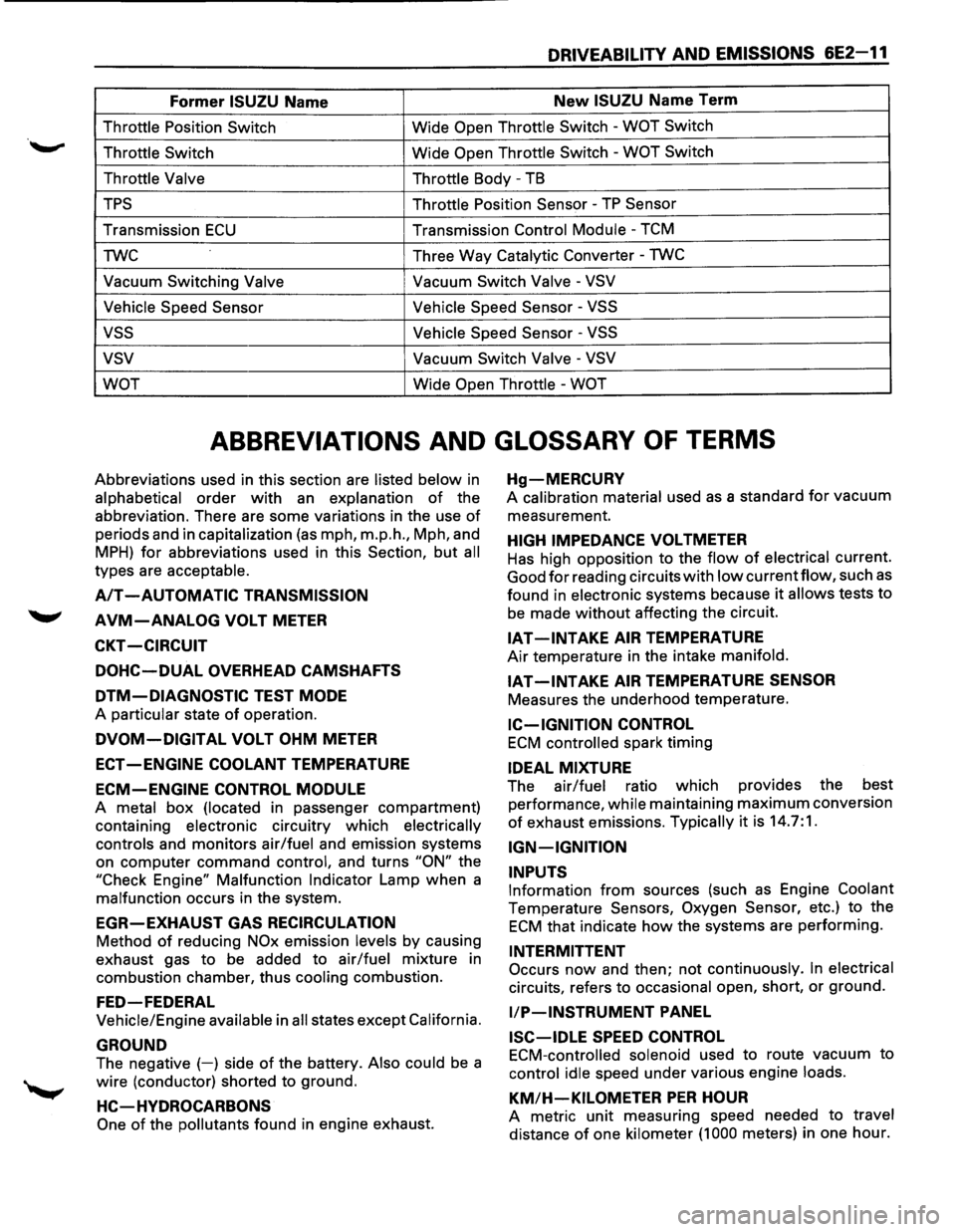
DRIVEABILITY AND EMISSIONS 6E2-11
Former ISUZU Name New ISUZU Name Term
Throttle Position Switch Wide Open Throttle Switch -WOT Switch
Throttle Switch
Wide Open Throttle Switch -WOT Switch
Throttle Valve Throttle
Body -TB
TPS Throttle Position Sensor -TP Sensor
Transmission ECU Transmission Control Module -TCM
TWC Three
Way
Catalytic Converter -TWC
Vacuum Switching Valve Vacuum Switch Valve -VSV
Vehicle Speed Sensor Vehicle
Speed Sensor
-VSS
vss Vehicle Speed Sensor -VSS
vsv Vacuum Switch Valve -VSV
WOT
Wide Open Throttle -WOT
ABBREVIATIONS AND GLOSSARY OF TERMS
Abbreviations used in this section are listed below in
alphabetical order with an explanation of the
abbreviation. There are some variations in the use
of
periods and in capitalization (as mph, m.p.h., Mph, and
MPH) for abbreviations used in this Section, but all
types are acceptable.
A/T -AUTOMATIC TRANSMISSION
AVM-ANALOG VOLT METER
CKT -CIRCUIT
DOHC-DUAL OVERHEAD CAMSHAFTS
DTM-DIAGNOSTIC TEST MODE
A particular state of operation.
DVOM-DIGITAL VOLT OHM METER
ECT -ENGINE COOLANT TEMPERATURE
ECM-ENGINE CONTROL MODULE
A metal box (located in passenger compartment)
containing
electronic circuitry which electrically
controls
and monitors air/fuel and emission systems
on
computer command control, and turns "ON" the
"Check Engine"
Malfunction Indicator Lamp when a
malfunction occurs in the system.
EGR-EXHAUST GAS RECIRCULATION
Method of reducing NOx emission levels by causing
exhaust gas
to be added to air/fuel mixture in
combustion chamber, thus
cooling combustion.
FED-FEDERAL
Vehicle/Engine available in all states except California.
GROUND
The negative (-) side of the battery. Also could be a
wire (conductor) shorted to ground.
HC-HVDROCARBONS
One of the pollutants found in engine exhaust.
Hg-MERCURV
A calibration material used as a standard for vacuum
measurement.
HIGH IMPEDANCE VOLTMETER
Has high opposition to the flow of electrical current.
Good
for reading circuits with low currentflow, such as
found in electronic systems because it allows tests to
be made without affecting the circuit.
IAT -INTAKE AIR TEMPERATURE
Air temperature in the intake manifold.
IAT-INTAKE AIR TEMPERATURE SENSOR
Measures the underhood temperature.
IC-IGNITION CONTROL
ECM controlled spark timing
IDEAL MIXTURE
The air/fuel ratio which provides the best
performance,
while maintaining maximum conversion
of exhaust emissions. Typically it is 14.7:1.
IGN-IGNITION
INPUTS
Information from sources (such as Engine Coolant
Temperature Sensors, Oxygen Sensor, etc.) to the
ECM that indicate how the systems are performing.
INTERMITTENT
Occurs now and then; not continuously. In electrical
circuits, refers to occasional open, short, or ground.
liP-INSTRUMENT PANEL
ISC-IDLE SPEED CONTROL
ECM-controlled solenoid used to route vacuum to
control idle speed under various engine loads.
KM/H-KILOMETER PER HOUR
A metric unit measuring speed needed to travel
distance of one kilometer (1 000 meters) in one hour.
Page 796 of 1928
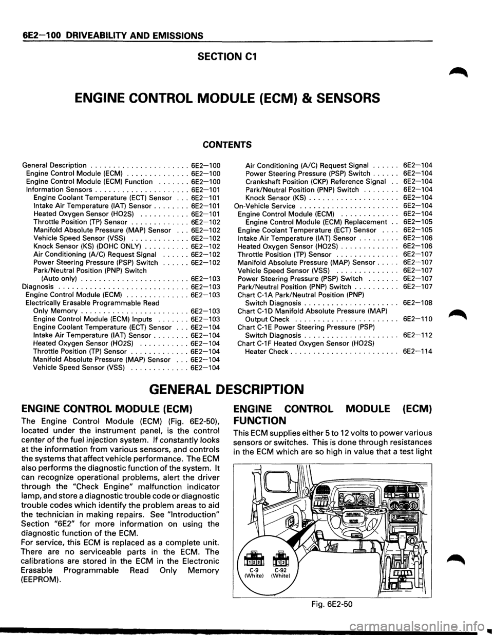
6E2-100 DRIVEABILITY AND EMISSIONS
SECTION C1
ENGINE CONTROL MODULE (ECM) & SENSORS
CONTENTS
General Description ...................... 6E2-1 00
Engine Control Module (ECM) .............. 6E2-100
Engine Control Module (ECM) Function ....... 6E2-1 00
Information Sensors ..................... 6E2-1 01
Engine Coolant Temperature (ECT) Sensor ... 6E2-101
Intake Air Temperature (IAT) Sensor ........ 6E2-101
Heated Oxygen Sensor (H02S) ........... 6E2-101
Throttle Position
(TP) Sensor ............. 6E2-102
Manifold Absolute Pressure (MAP) Sensor ... 6E2-102
Vehicle Speed Sensor (VSS) ............. 6E2-102
Knock Sensor (KS) (DOHC ONLY) .......... 6E2-102
Air Conditioning (A/C) Request Signal ...... 6E2-1 02
Power Steering Pressure (PSP) Switch ...... 6E2-1 02
Park/Neutral Position (PNP) Switch
(Auto only)
........................ 6E2-1 03 Diagnosis ............................. 6E2-1 03
Engine Control Module (ECM) .............. 6E2-1 03
Electrically Erasable Programmable Read
Only Memory ........................ 6E2-1 03
Engine Control Module (ECM) Inputs ....... 6E2-103
Engine Coolant Temperature (ECT) Sensor ... 6E2-1 04
Intake Air Temperature (IAT) Sensor ........ 6E2-1 04
Heated Oxygen Sensor
(H02S) ........... 6E2-1 04
Throttle Position
(TP) Sensor ............. 6E2-1 04
Manifold Absolute Pressure (MAP) Sensor
... 6E2-1 04
Vehicle Speed Sensor (VSS) ............. 6E2-1 04
Air Conditioning (A/C) Request Signal
Power Steering Pressure
(PSP) Switch ..... .
Crankshaft Position
(CKP) Reference Signal ..
Park/Neutral Position (PNP) Switch ....... .
Knock Sensor
(KS) ................... .
On-Vehicle Service ..................... .
Engine Control Module
(ECM) ............ .
Engine Control Module
(ECM) Replacement ..
Engine Coolant Temperature (ECT) Sensor ... .
Intake Air Temperature (IAT) Sensor ........ .
Heated Oxygen Sensor
(H02S) ............ .
Throttle Position
(TP) Sensor ............. .
Manifold Absolute Pressure (MAP) Sensor
.... .
Vehicle Speed Sensor
(VSS) ............. .
Power Steering Pressure
(PSP) Switch ...... .
Park/Neutral Position
(PNP) Switch ......... .
Chart C-1A Park/Neutral Position
(PNP)
Switch Diagnosis .................... .
Chart
C-1 D Manifold Absolute Pressure (MAP)
Output Check
...................... .
Chart
C-1 E Power Steering Pressure (PSP)
Switch Diagnosis .................... .
Chart
C-1 F Heated Oxygen Sensor (H02S)
Heater Check ....................... .
6E2-104
6E2-104
6E2-104
6E2-104
6E2-104
6E2-104
6E2-104
6E2-105
6E2-105
6E2-106
6E2-106
6E2-107
6E2-107
6E2-107
6E2-107
6E2-107
6E2-108
6E2-110
6E2-112
6E2-114
GENERAL DESCRIPTION
ENGINE CONTROL MODULE (ECM)
The Engine Control Module (ECM) (Fig. 6E2-50),
located under the instrument panel, is the control
center of the fuel injection system. If constantly looks
at the information from various sensors, and controls
the systems that affect vehicle performance. The ECM
also performs the diagnostic function of the system. It
can recognize operational problems, alert the driver
through the "Check Engine" malfunction indicator
lamp, and store a diagnostic trouble code or diagnostic
trouble codes which identify the problem areas to aid
the technician in making repairs.
See "Introduction"
Section "6E2" for more information on using the
diagnostic function
of the ECM.
For service, this ECM is replaced as a complete unit.
There are no serviceable parts in the
ECM. The
calibrations are stored in the
ECM in the Electronic
Erasable Programmable Read Only Memory
(EEPROM).
ENGINE CONTROL MODULE (ECM)
FUNCTION
This ECM supplies either 5 to 12 volts to power various
sensors
or switches. This is done through resistances
in the
ECM which are so high in value that a test light
Fig. 6E2-50