torque ISUZU TROOPER 1995 Workshop Manual
[x] Cancel search | Manufacturer: ISUZU, Model Year: 1995, Model line: TROOPER, Model: ISUZU TROOPER 1995Pages: 1928
Page 1027 of 1928
... ......,.
AUTOMATIC TRANSMISSION (4L30-E) 7A-155
ON-VEHICLE SERVICE
CHECKING TRANSMISSION FLUID
LEVEL
1. Park the vehicle on level ground.
2. Apply the parking brake.
3. Place the automatic transmission in "Park" and
start the engine.
Allow the engine to idle for
two minutes.
4. With the brakes applied, move the shifter lever
through all the gear ranges, ending in "Park".
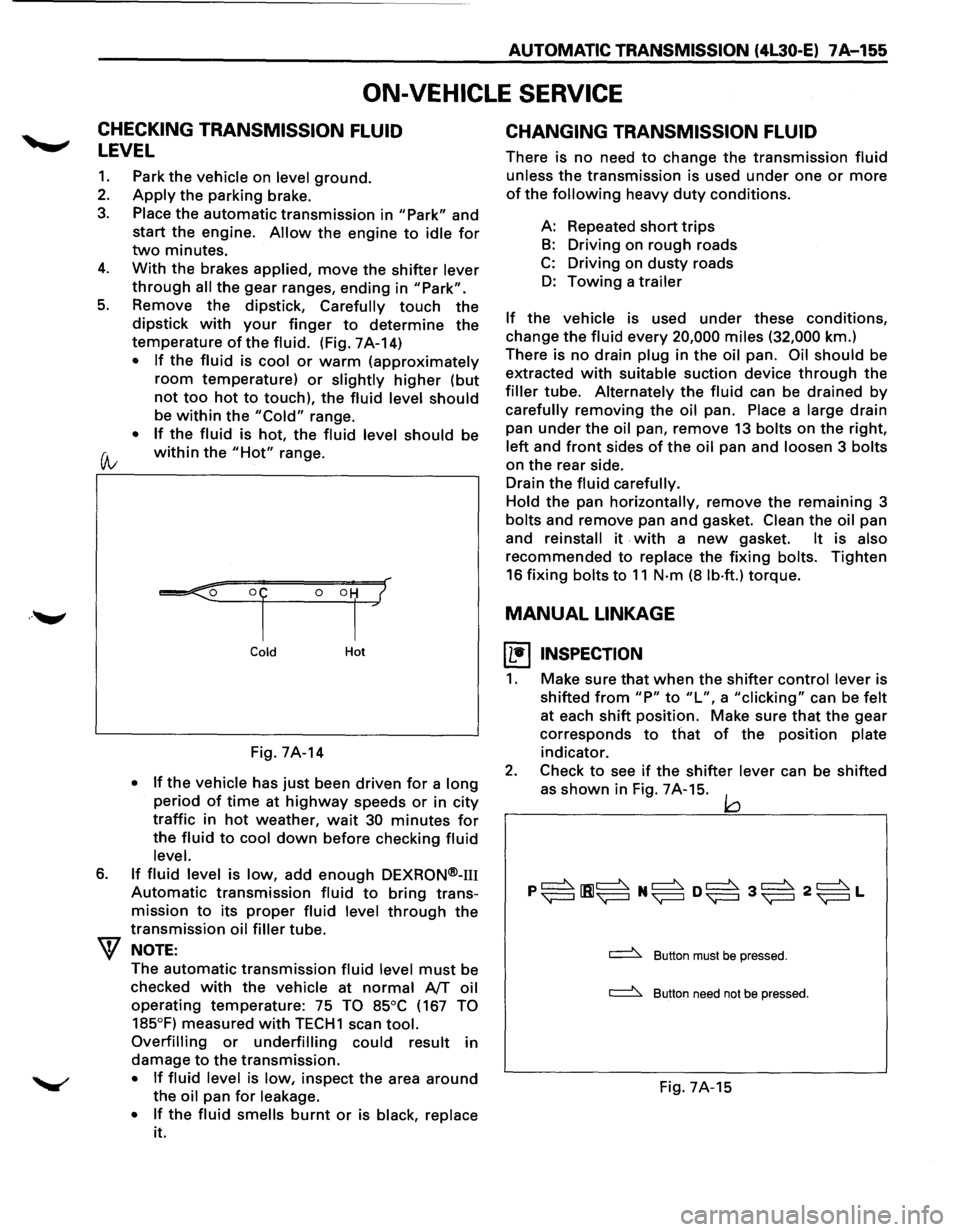
5. Remove the dipstick, Carefully touch the
dipstick with your finger to determine the
temperature of the fluid. (Fig. 7A-14)
• If the fluid is cool or warm (approximately
room temperature) or slightly higher (but
not too hot to touch), the fluid level should
be within the "Cold" range.
• If the fluid is hot, the fluid level should be
(A; within the "Hot" range.
6.
Cold Hot
Fig. 7A-14
• If the vehicle has just been driven for a long
period of time at highway speeds or in city
traffic in hot weather, wait 30 minutes for
the fluid to cool down before checking fluid
level.
If fluid level is low, add enough DEXRON®-m
Automatic transmission fluid to bring trans
mission
to its proper fluid level through the
transmission oil filler tube.
NOTE:
The automatic transmission fluid level must be
checked
with the vehicle at normal AfT oil
operating temperature: 75 TO 85°C (167 TO
185°F)
measured with TECH1 scan tool.
Overfilling or underfilling could result in
damage
to the transmission.
• If fluid level is low, inspect the area around
the oil pan for leakage.
•
If the fluid smells burnt or is black, replace
it.
CHANGING TRANSMISSION FLUID
There is no need to change the transmission fluid
unless the transmission is used under one or more
of the following heavy duty conditions.
A: Repeated
short trips
B: Driving on rough roads
C: Driving on dusty roads
D: Towing a trailer
If the vehicle is used under these conditions,
change the fluid every 20,000 miles (32,000 km.)
There is
no drain plug in the oil pan. Oil should be
extracted
with suitable suction device through the
filler tube. Alternately the fluid can be drained by
carefully removing the oil pan. Place a large drain
pan
under the oil pan, remove 13 bolts on the right,
left and front sides of the oil pan and loosen 3 bolts
on the rear side.
Drain
the fluid carefully.
Hold
the pan horizontally, remove the remaining 3
bolts and remove pan and gasket. Clean the oil pan
and
reinstall it . with a new gasket. It is also
recommended to replace the fixing bolts. Tighten
16 fixing bolts to 11 N·m (8 lb·ft.) torque.
MANUAL LINKAGE
~ INSPECTION
1. Make sure that when the shifter control lever is
shifted
from "P" to "L", a "clicking" can be felt
at each shift position. Make sure that the gear
corresponds
to that of the position plate
indicator.
2. Check to see if the shifter lever can be shifted
as
shown in Fig. 7A-15. jQ
~ Button must be pressed.
~ Button need not be pressed.
Fig. 7A-15
Page 1028 of 1928
7A-156 AUTOMATIC TRANSMISSION (4L30-E)
SELECTOR LEVER
B REMOVAL
Preparation:
• Disconnect negative (-) battery cable.
(}-
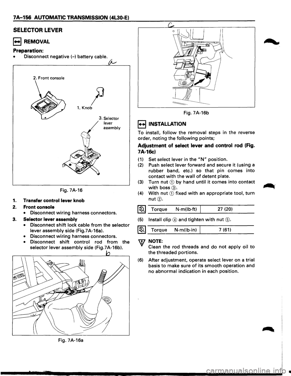
2. Front console
)3
1. Knob
Fig. 7A-16
1. Transfer control lever knob
2. Front console
3. Selector
lever
assembly
• Disconnect wiring harness connectors.
3. Selector lever assembly
• Disconnect shift lock cable from the selector
lever assembly
side (Fig.7A-16a).
• Disconnect wiring harness connectors.
• Disconnect shift control rod from the
selector lever assembly side (Fig.7A-16b).
Fig. 7A-16a Fig.
7A-16b
I••IINSTALLATION
To install, follow the removal steps in the reverse
order,
notin!~ the following points;
Adjustment of select lever and control rod (Fig.
7A-16c)
(1) Set sele1ct lever in the "N" position.
(2) Push select lever forward and secure it (using a
rubber band, etc.) so that pin comes into
contact with the wall of detent plate.
(3) Turn nut CD by hand until it comes into contact
with boss@.
(4) With nut CD fixed with an appropriate tool, turn
nut®.
~~~ Torque N·mOb·ft) I 27 (20)
(5) Install clip @ and tighten with nut @.
~~~ Torque N·m(lb·in) I 7 (61)
w NOTE:
Clean the rod threads and do not apply oil to
the threaded portions.
(6) After adjustment, operate select lever on a trial
basis to make sure of its smooth operation and
no
abnormal indication in each position.
.......
..._.
II
Page 1029 of 1928
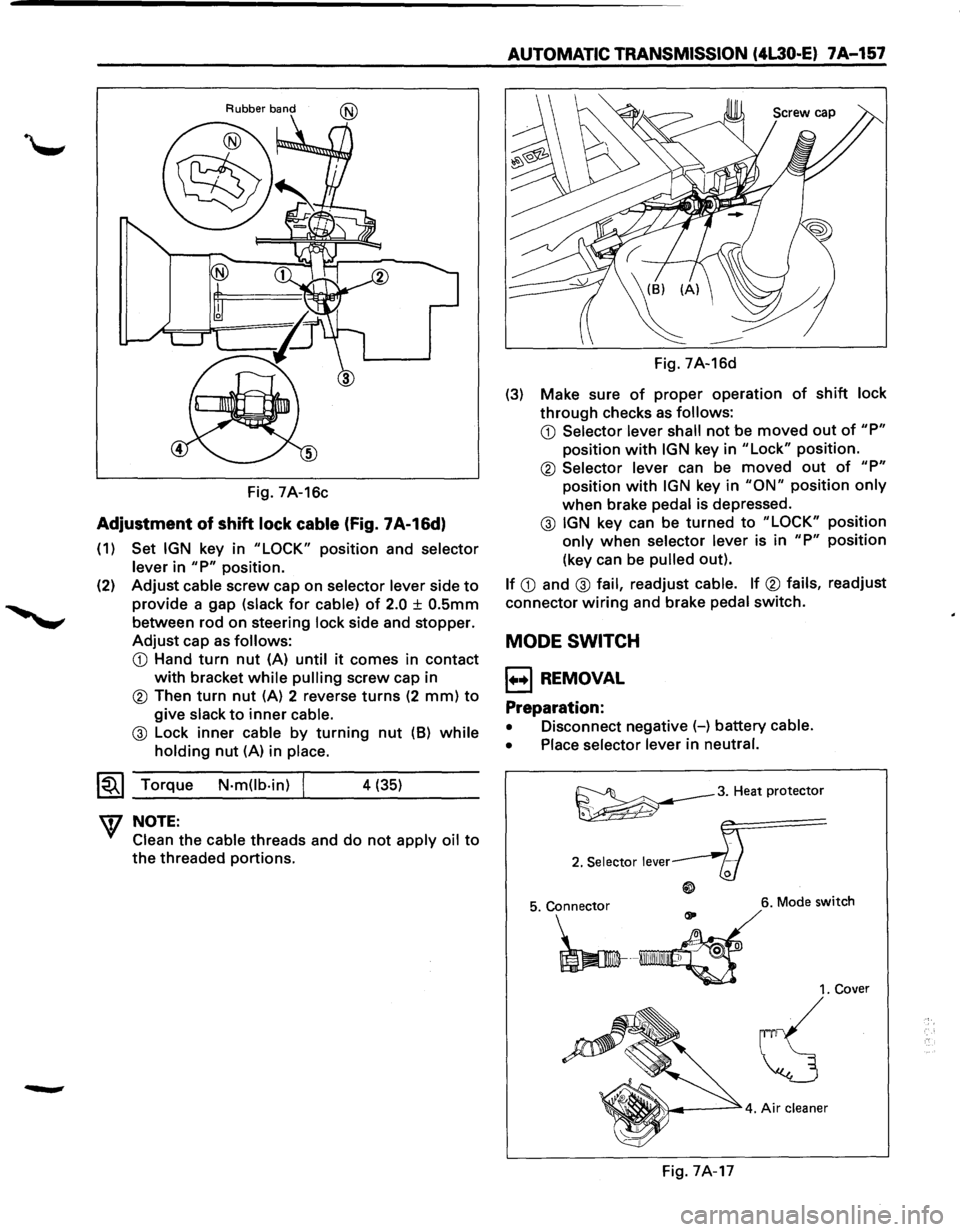
Rubber band
Fig. 7A-16c
Adjustment of shift lock cable (Fig. 7A-16d)
(1) Set IGN key in "LOCK" position and selector
lever
in "P" position.
(2)
Adjust cable screw cap on selector lever side to
provide a gap (slack for cable) of 2.0 ± O.Smm
between rod on steering lock side and stopper.
Adjust cap as follows:
CD Hand turn nut (A) until it comes in contact
with bracket while pulling screw cap in
® Then turn nut (A) 2 reverse turns (2 mm) to
give slack to inner cable.
@ Lock inner cable by turning nut (8) while
holding nut (A) in place.
~~~ Torque N-m(lb-in) j 4 (35)
W NOTE:
Clean the cable threads and do not apply oil to
the threaded portions.
AUTOMATIC TRANSMISSION (4L30·E) 7A-157
Fig. 7A-16d
(3) Make sure of proper operation of shift lock
through checks as follows:
CD Selector lever shall not be moved out of "P"
position with IGN key in "Lock" position.
® Selector lever can be moved out of "P"
position with IGN key in "ON" position only
when brake pedal is depressed.
@ IGN key can be turned to "LOCK" position
only when selector lever is in "P" position
(key can be
pulled out).
If CD and @ fail, readjust cable. If ® fails, readjust
connector
wiring and brake pedal switch.
MODE SWITCH
1++1 REMOVAL
Preparation:
• Disconnect negative (-) battery cable.
• Place selector lever
in neutral.
~3. Heat protector
2. Selector lever
6. Mode switch
1. Cover
~
Fig. 7A-17
Page 1030 of 1928
7A-158 AUTOMATIC TRANSMISSION (4L30-E)
1. Mode switch cover
2.
Selector lever
• Disconnect selector lever from the mode
switch.
3. Heat protector
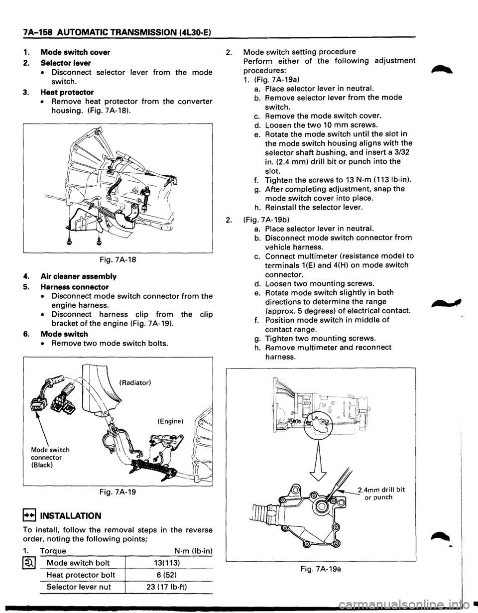
• Remove heat protector from the converter
housing. (Fig. 7A-18).
Fig. 7A-18
4. Air cleaner assembly
5. Harness connector
• Disconnect mode switch connector from the
engine harness.
• Disconnect harness clip from the clip
bracket ofthe engine (Fig. 7A-19).
6. Mode switch
• Remove two mode switch bolts.
Mode switch
connector
(Black)
(Radiator)
(Engine)
Fig. 7A-19
I••! INSTALLATION
To install, follow the removal steps in the reverse
order,
noting the following points;
1. Torque
~~~ Mode switch bolt
Heat protector bolt
Selector lever nut
N·m Ob·in)
13(113)
6 (52)
23 ( 17 lb·ft)
2. Mode switch setting procedure
Perform either
of the following adjustment
procedures:
1. (Fig. 7A-19a)
a. Place selector lever in neutral.
b. Remove selector lever from the mode
switch.
c. Remove the mode switch cover.
d. Loosen the
two 10 mm screws.
e. Rotate the mode switch until the slot in
the mode switch housing aligns with the
selector shaft bushing, and insert a 3/32
in. (2.4
mm) drill bit or punch into the
sllot.
f. Tighten the screws to 13 N·m (113 lb·in).
g. After completing adjustment, snap the
mode switch cover into place.
h. Reinstall the selector lever.
2. (Fig. 7 A.-19b)
a. Place selector lever in neutral.
b. Disconnect mode switch connector from
vehicle harness.
c. Connect multimeter (resistance mode) to
terminals 1(E) and 4(H) on mode switch
connector.
d.
Loosen two mounting screws.
e. Rotate mode switch slightly in both
diirections to determine the range
(approx.
5 degrees) of electrical contact.
f. Position
mode switch in middle of
contact range.
g. Tighten
two mounting screws.
h. Remove multimeter and reconnect
harness.
Fig. 7A-19a
..
•
Page 1032 of 1928
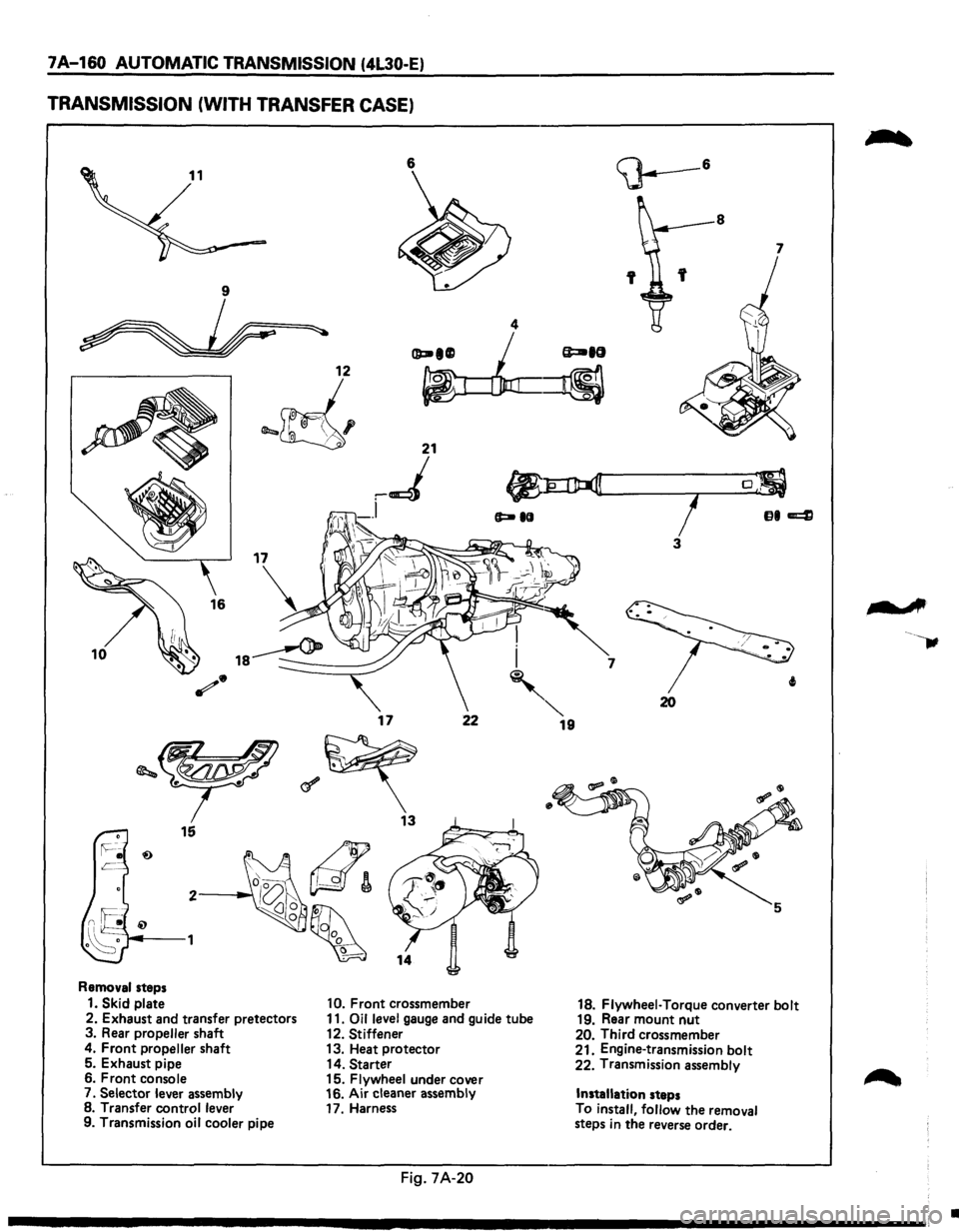
7A-160 AUTOMATIC TRANSMISSION (4L30-E)
TRANSMISSION (WITH TRANSFER CASE)
6
I
10 i
'
17 22
Removal steps
1. Skid plate 10. Front crossmember
2. Exhaust and transfer pretectors 11. Oil level gauge and guide tube
3. Rear propeller shaft
12. Stiffener
4. Front propeller shaft 13. Heat protector
5. Exhaust pipe
14. Starter
6. Front console
15. Flywheel under cover
7.
Selector lever assembly 16.
Air cleaner assembly
8. Transfer control lever
17. Harness
9. Transmission
oil cooler pipe
Fig. 7A-20
""' 19
8
7
7
20
18. Flywheel· Torque converter bolt 19. Rear mount nut 20. Third crossmember
21. Engine-transmission bolt
22. Transmission assembly
Installation steps
To
install, follow the removal
steps in the reverse order.
-A
•
Page 1034 of 1928
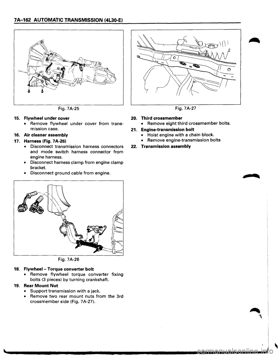
7A-162 AUTOMATIC TRANSMISSION (4L30-E)
Fig. 7A-25
15. Flywheel under cover
• Remove flywheel under cover from trans
mission case.
16. Air cleaner assembly
17. Harness (Fig. 7A-26)
• Disconnect transmission harness connectors
and mode switch harness connector
from
engine harness.
• Disconnect harness clamp from engine clamp
bracket.
• Disconnect ground cable from engine.
Fig. 7A-26
18. Flywheel-Torque converter bolt
• Remove flywheel torque converter fixing
bolts (3 pieces) by turning crankshaft.
19. Rear Mount Nut
• Support transmission with a jack.
• Remove two rear mount nuts from the 3rd
crossmember side (Fig. 7A-27). Fig.
7A-27
20. Third cr·ossmember
• Remove eight third crossmember bolts.
21. Engine-transmission bolt
• Hoist engine with a chain block.
•
Remove engine-transmission bolts
22. Transmission assembly
Page 1035 of 1928
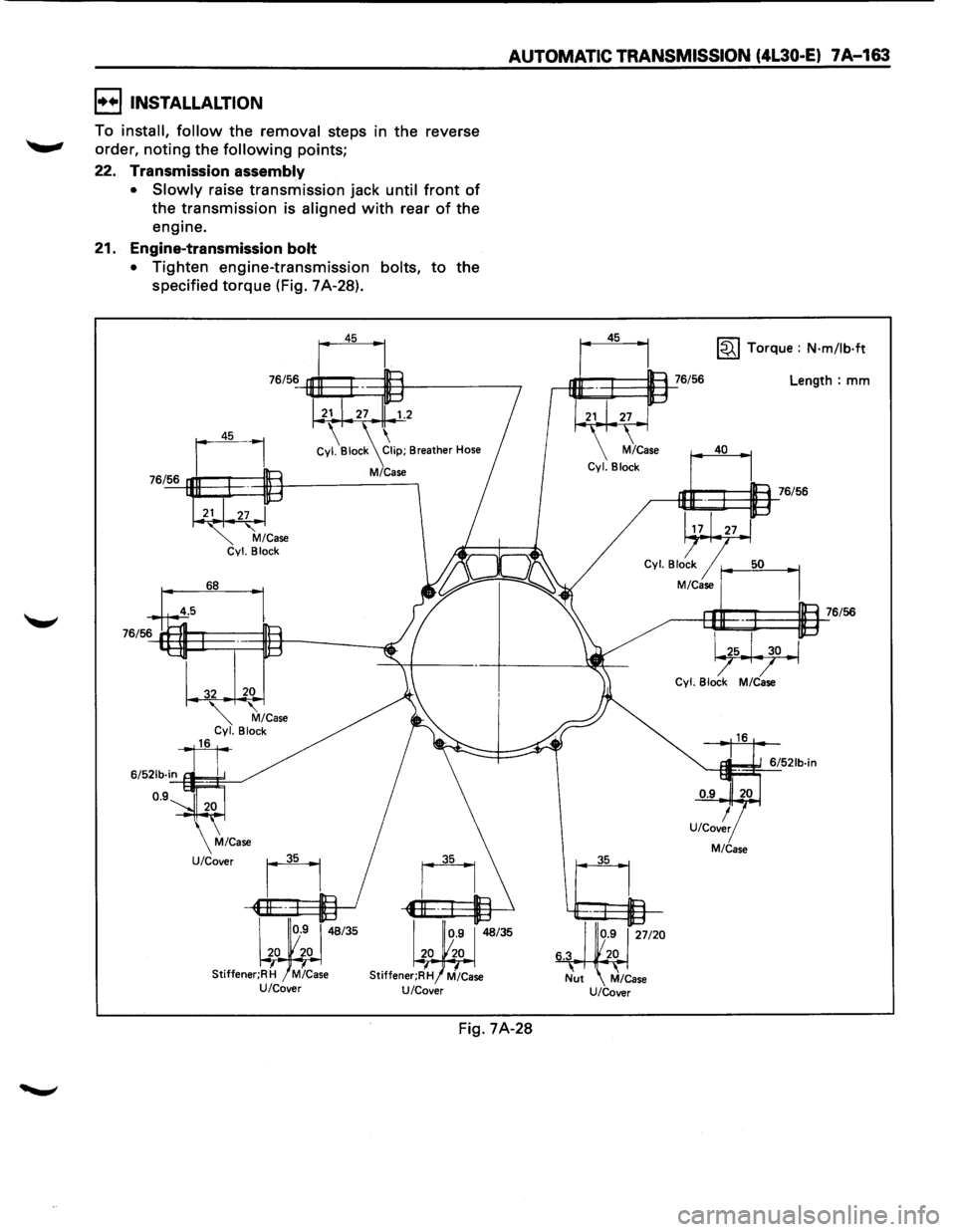
AUTOMATIC TRANSMISSION (4L30-E) 7A-163
I••IINSTALLALTION
To install, follow the removal steps in the reverse
order,
noting the following points;
22. Transmission assembly
•
Slowly raise transmission jack until front of
the transmission is aligned with rear of the
engine.
21. Engine-transmission
bolt
•
Tighten engine-transmission bolts, to the
specified
torque (Fig. 7A-28).
76/56
21 27 1.2
Cy~Bioc~21ip; Breather Hose
M/Case
68
Stiffener;R H M/Case U/Cover
Fig. 7A-28
45
35 ~ Torque : N·m/lb·ft
Length: mm
40
,---iEJE~I:=ll=1_::76/56
Cyl Blo~ r--1
M/Case J
1
-------e9E~~=~a.l_76/56
~ Cyl. Block M/Case
M/Case
Page 1036 of 1928
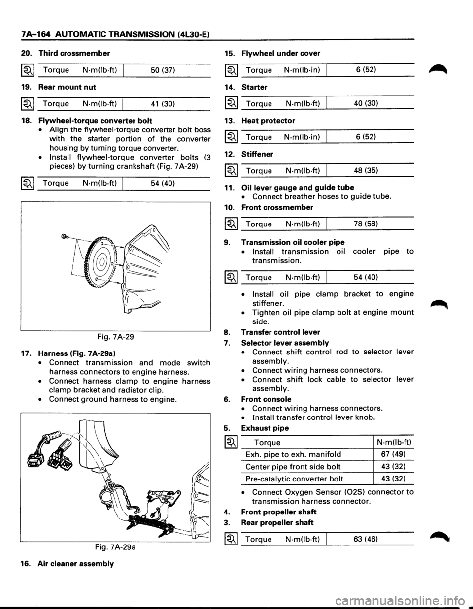
7A-164 AUTOMATIC TRANSMISSION (4L30-E)
20. Third crossmember
~~~ Torque N·m(lb.ft) 50 (37)
19. Rear mount nut
~~~ Torque N·mOb·ft) 41 (30)
18. Flywheel-torque converter bolt
• Align
the flywheel-torque converter bolt boss
with the starter portion of the converter
housing
by turning torque converter.
• Install flywheel-torque converter bolts (3
pieces) by turning crankshaft (Fig. 7 A-29)
~~~ Torque N·mOb·ft) 54 (40)
Fig. 7A-29
17. Harness (fig. 7A-29a)
• Connect transmission and mode switch
harness connectors to engine harness.
• Connect harness clamp to engine harness
clamp bracket and radiator clip.
•
Connect ground harness to engine.
Fig. 7A-29a
16. Air
cleaner assembly
15. Flywheel under cover
~~~ TorqUte N·mOb·in)
14. Starter
~~~ Torqu,e N·m(lb·ft)
13. Heat protector
~~~ Torqu'e N·m(lb·in)
12. Stiffener
N·m(lb·ft)
11. Oil lever gauge and guide tube 6
(52)
40 (30)
6 (52)
48 (35)
• Connect breather hoses to guide tube.
10. Front crossmember
~~~ Torque N·m(lb·ft) I 78 (58)
9. Transmission oil cooler pipe
• Install transmission oil cooler pipe to
transmission.
~~~ Torqwe N·m(lb·ft) I 54 (40)
•
lnsta1ll oil pipe clamp bracket to engine
stiffener. .~
• Tighten oil pipe clamp bolt at engine mount
side.
8. Transfer control lever
7. Selector lever assembly
•
Connect shift control rod to selector lever
assembly.
•
Connect wiring harness connectors.
• Connect shift lock cable to selector lever
assembly.
6. Front cc>nsole
• Connect wiring harness connectors.
• Install transfer control lever knob.
5. Exhaust pipe
I~I ___ T_o_r_q~_ue __________________ 4-N_·_m_(l_b_·ft __ )
Exh. pipe
to exh. manifold 67 (49)
Center pipe
front side bolt 43 (32)
Pre-catalytic converter bolt 43 (32)
• Connect Oxygen Sensor (025) connector to
transmission harness connector.
4. Front propeller shaft
3. Rear propeller shaft
~~~ Torqwe N·mOb·ft) 63 (46)
Page 1037 of 1928
2. Exhaust and transfer protectors
~~~ Torque N-m(lb.ft) 37 (27)
1. Skid plate
• Connect negative (-) battery cable.
• Install
engine hood.
• Adjust shift lock cable.
Refer to "Selector lever" in this section.
SOLENOID VALVE
(MAIN CASE VALVE BODY)
l••l REMOVAL
Preparation:
• Disconnect negative {-) battery cable.
•
Remove exhaust protector and exhaust pipe.
1. Main case oil pan
• Remove sixteen 10 mm screws, main case
oil pan, magnet, and gasket.
• Drain fluid.
Refer to "CHANGING TRANSMISSION
FLUID".
2. Oil filter
• Remove three 13 mm screws, oil filter.
3. Wiring harness
• Disconnect wiring harness from band control
solenoid,
shift solenoids and main case 4 pin
connector.
Pull only on connectors, not on
wiring harness.
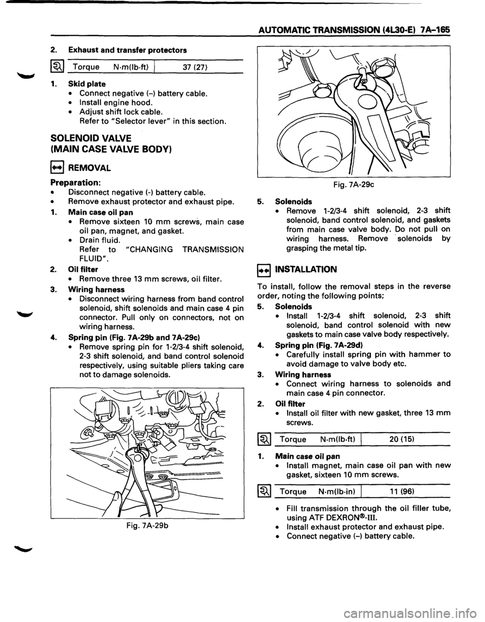
4. Spring pin (Fig. 7 A-29b and 7 A-29c)
• Remove spring pin for 1-2/3-4 shift solenoid,
2-3 shift solenoid, and band control solenoid
respectively,
using suitable pliers taking care
not to damage solenoids.
Fig. 7A-29b
AUTOMATIC TRANSMISSION (4L30 .. E) 7A-165
Fig. 7A-29c
5. Solenoids
• Remove 1-2/3-4 shift solenoid, 2-3 shift
solenoid, band control solenoid, and gaskets
from main case valve body. Do not pull on
wiring harness. Remove
· solenoids by
grasping the
metal tip.
I••! INSTALLATION
To install, follow the removal steps in the reverse
order,
noting the following points;
5. Solenoids
• Install 1-2/3-4 shift solenoid, 2-3 shift
solenoid, band control solenoid with new
gaskets to main case valve body respectively.
4. Spring pin (Fig. 7 A·29d)
• Carefully install spring pin with hammer to
avoid damage to valve body etc.
3. Wiring harness
• Connect wiring harness to solenoids and
main case 4 pin connector.
2. Oil filter
• Install oil filter with new gasket, three 13 mm
screws.
~~~ Torque N·m(lb.ft) 20 (15)
1. Main case oil pan
•
Install magnet, main case oil pan with new
gasket, sixteen 10 mm screws.
1~1 Torque N·m(lb·in) J 11 (96)
• Fill transmission through the oil filler tube,
using ATF DEXRQN®-m.
• Install exhaust protector and exhaust pipe.
• Connect negative (-) battery cable.
Page 1038 of 1928
7A-166 AUTOMATIC TRANSMISSION (4l30-E)
Fig. 7A-29d
SOLENOID VALVE
(ADAPTER CASE VALVE BODY)
l++l REMOVAL
Preparation:
• Disconnect negative(-) battery cable.
• Remove exhaust protector and exhaust pipe.
• Drain fluid.
• Refer to "CHANGING TRANSMISSION FLUID".
1. Adapter case oil pan
• Remove twelve 10 mm screws, adapter case
oil pan, and gasket.
NOTE:
Oil pan still contains transmission fluid. Place a
large
drain container under the oil pan.
Drain
the fluid carefully.
2. Wiring harness
• Disconnect wiring harness from force motor
solenoid, converter clutch solenoid and 5
pin
connector of adapter case. Pull only on
connectors,
not on wiring harness.
Fig. 7A-29e Fig.
7A-29f
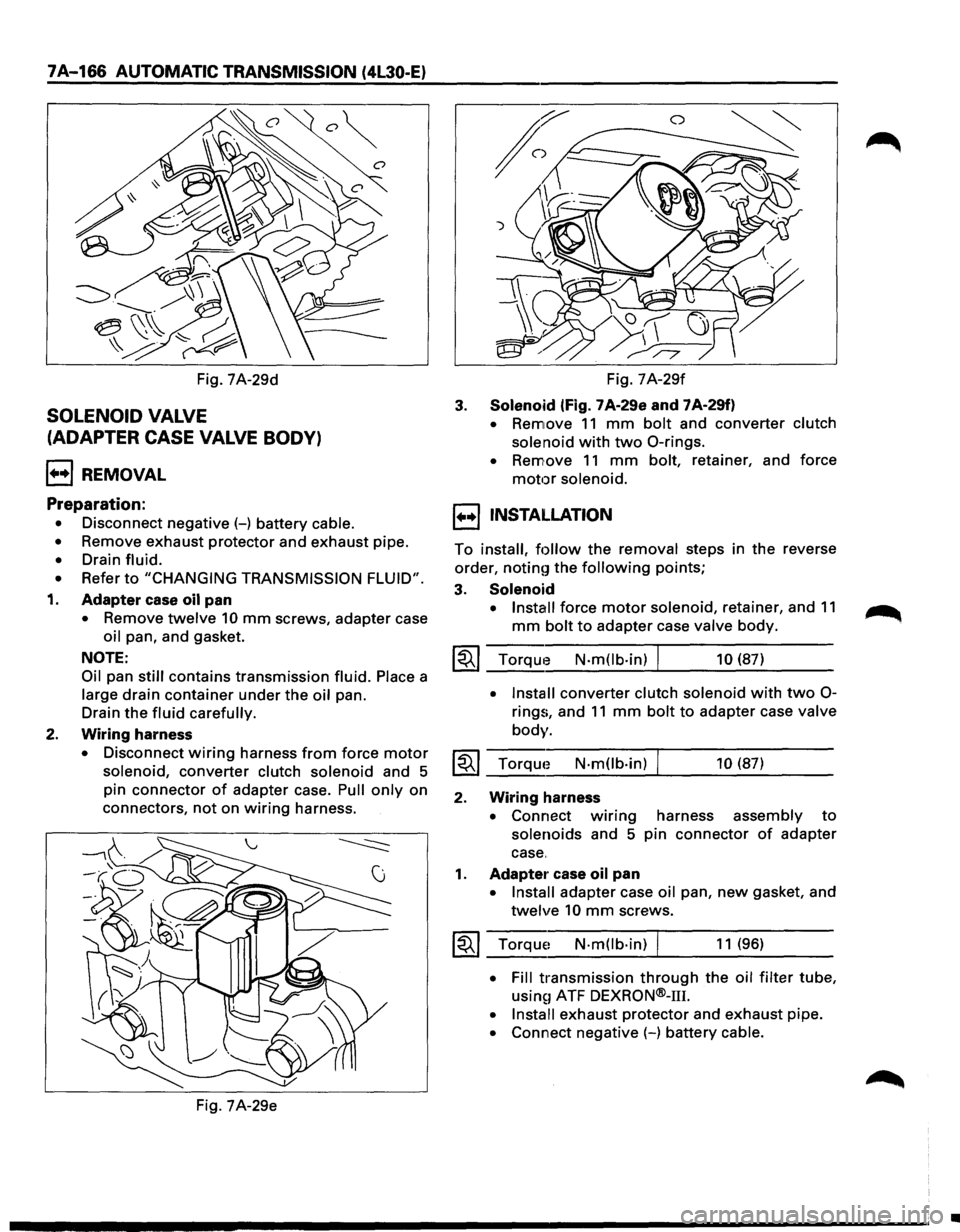
3. Solenoid (fig. 7 A-29e and 7 A-29f)
• Remove 11 mm bolt and converter clutch
solenoid
with two 0-rings.
• Remove 11 mm bolt, retainer, and force
motor solenoid.
1••1 INSTALLATION
To install, follow the removal steps in the reverse
order,
noting the following points;
3. Solenoid
• Install force motor solenoid, retainer, and 11
mm bolt to adapter case valve body.
~~~ Torque N-m(lb-in) I 10 (87)
• Install converter clutch solenoid with two 0-
rings, and 11 mm bolt to adapter case valve
body.
~~~ Torque N-mOb·in) 10 (87)
2. Wiring harness
• Connect w1nng harness assembly to
solenoids and 5 pin connector of adapter
case.
1. Adapter case oil pan
• Install adapter case oil pan, new gasket, and
twelve 10 mm screws.
~~~ Torque~ N·mOb·in) I 11 (96)
• Fill transmission through the oil filter tube,
usin~1 ATF DEXRON®-111.
• Install exhaust protector and exhaust pipe.
• Connect negative (-) battery cable.
•