torque ISUZU TROOPER 1995 Workshop Manual
[x] Cancel search | Manufacturer: ISUZU, Model Year: 1995, Model line: TROOPER, Model: ISUZU TROOPER 1995Pages: 1928
Page 1039 of 1928
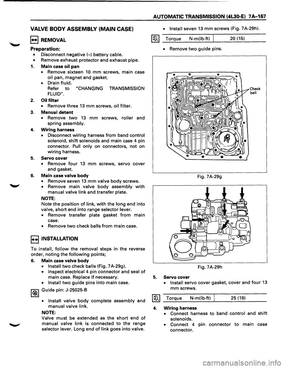
VALVE BODY ASSEMBLY (MAIN CASE)
1••1 REMOVAL
Preparation:
• Disconnect negative (-) battery cable.
• Remove exhaust protector and exhaust pipe.
1. Main case oil pan
• Remove sixteen 10 mm screws, main case
oil pan,
magnet and gasket.
• Drain fluid.
Refer
to "CHANGING TRANSMISSION
FLUID".
2. Oil filter
•
Remove three 13 mm screws, oil filter.
3. Manual detent
• Remove two 13 mm screws, roller and
spring assembly.
4. Wiring harness
• Disconnect wiring harness from band control
solenoid, shift solenoids and main
case 4 pin
connector.
Pull only on connectors, not on
wiring harness.
5.
Servo cover
• Remove four 13 mm screws, servo cover
and gasket.
6. Main case valve body
• Remove seven 13 mm valve body screws.
• Remove main valve body assembly with
manual valve link and transfer plate.
NOTE:
Note the position of link, with the long end into
valve, short end into range selector lever.
• Remove transfer plate gasket from main
case.
• Remove two check balls from main case.
I••IINSTALLATION
To install, follow the removal steps in the reverse
order,
noting the following points;
6. Main
case valve body
• Install two check balls (Fig. 7 A-29g).
• Inspect electrical 4 pin connector and seal of
main case. Replace if necessary.
• Install two guide pins into main case.
1®.1 Guide pin: J-25025-B
• Install
valve body complete assembly and
manual valve link.
NOTE:
Valve must be extended as the short end of
manual valve link is connected to the range
selector lever. Long end
of link goes into valve.
AUTOMATIC TRANSMISSION (4L30-E) 7A-167
• Install seven 13 mm screws (Fig. 7A-29h).
~~~ Torque N·m(lb·ft) I 20 (15)
5.
4.
• Remove two guide pins.
Fig. 7A-29g
Fig. 7A-29h
Servo cover
Check ball
• Install servo cover gasket, cover and four 13
mm screws.
Torque
N·mOb·ft) I 25 (18)
Wiring harness
• Connect harness to band control and shift
solenoids.
• Connect 4 pin connector to main case
connector.
Page 1040 of 1928
7A-168 AUTOMATIC TRANSMISSION (4L30-E)
3. Manual detent
• Install roller and spring assembly.
• Install
two 13 mm screws.
~~~ Torque N·m(lb.ft) I 20 (15)
2. Oil filter
• Install oil filter and three 13 mm screws.
~~~ Torque N-m(lb.ft) I 20 (15)
1. Main case oil pan
• Install oil pan gasket, magnet, oil pan and
sixteen
10 mm screws.
~~~ Torque N·m(lb-in) I 11 (96)
• Fill transmission through the oil filler tube,
using ATF
DEXRON®-111.
• Install exhaust pipe and exhaust protector.
• Connect negative (-) battery cable.
VALVE BODY ASSEMBLY (ADAPTER CASE)
1++1 REMOVAL
Preparation:
• Disconnect negative (-) battery cable.
•
Remove exhaust protector and exhaust pipe.
• Drain fluid.
•
Refer to "CHANGING TRANSMISSION FLUID".
1. Adapter case oil pan
• Remove twelve 10 mm screws, adapter case
oil pan and gasket.
NOTE:
Oil pan still contains transmission fluid. Place a
large drain container under the oil pan.
Drain the
fluid carefully.
2. Wiring harness
• Disc;:mnect wiring harness from force motor
solenoid, converter clutch solenoid and 5
pin
connector of adapter case. Pull only on
connectors,
not on wiring harness.
• Remove wiring harness.
3. Adapter case valve body
• Seve~n 13 mm screws, adapter case valve
body assembly, transfer plate and two
gaskets.
1++1 INSTALLATION
To install, follow the removal steps in the reverse
order,
notin~r the following points;
3. Adapter case valve body
• Inspect electrical 5 pin connector and seal of
adapter case. Replace if necessary.
• Install wiring harness assembly in bottom
of adapter case.
• Install gasket, transfer plate and gasket.
• Install adapter case valve body complete
and seven 13 mm screws.
~~~ Torque1 N·mOb·ft) 20 (15)
2. Wiring harness
• Connect harness assembly to converter
clutch solenoid and force motor.
1. Adapter case oil pan
• Instal!! oil pan gasket, oil pan and twelve 10
mm screws.
~~~ Torque N-m(lb-in) I 11 (96)
• Fill transmission through the oil filter tube,
using1 ATF DEXRON®-m.
• Install exhaust pipe and exhaust protector. ~
• Connect negative (-) battery cable.
•
Page 1041 of 1928
TRANSMISSION CONTROL MODULE (TCM)
1+•1 REMOVAL
Preparation:
• Disconnect negative (-) battery cable.
1. Wiring harness connector
• Disconnect TCM wiring harness connector
from TCM.
2. TCM
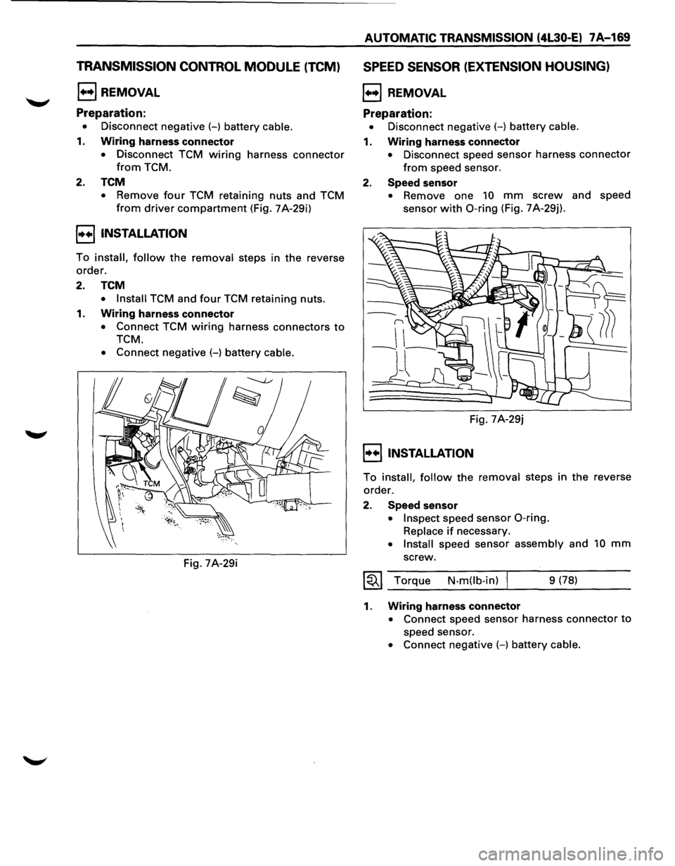
• Remove four TCM retaining nuts and TCM
from driver compartment (Fig. 7A-29i)
!•+I INSTALLATION
To install, follow the removal steps in the reverse
order.
2. TCM
• Install TCM and four TCM retaining nuts.
1. Wiring harness connector
• Connect TCM wiring harness connectors to
TCM.
• Connect negative (-) battery cable.
Fig. 7A-29i
AUTOMATIC TRANSMISSION (4L30-El 7A-169
SPEED SENSOR (EXTENSION HOUSING)
1+•1 REMOVAL
Preparation:
• Disconnect negative (-) battery cable.
1. Wiring harness connector
• Disconnect speed sensor harness connector
from speed sensor.
2. Speed sensor
• Remove one 10 mm screw and speed
sensor
with 0-ring (Fig. 7 A-29j).
Fig. 7A-29j
I•+IINSTALLATION
To install, follow the removal steps in the reverse
order.
2. Speed sensor
• Inspect speed sensor 0-ring.
Replace if necessary.
• Install speed sensor assembly and 10 mm
screw.
~~~ Torque N·mOb·in) 9 (78)
1. Wiring harness connector
• Connect speed sensor harness connector to
speed sensor.
• Connect negative (-) battery cable.
Page 1042 of 1928
7 A-170 AUTOMATIC TRANSMISSION (4L30-E)
TRANSMISSION OIL TEMPERATURE
SENSOR (ADAPTER CASE)
1•+1 REMOVAL
Preparation:
• Disconnect negative (-) battery cable.
•
Remove exhaust protector and exhaust pipe.
• Drain fluid.
•
Refer to "CHANGING TRANSMISSION FLUID".
1. Adapter case oil pan
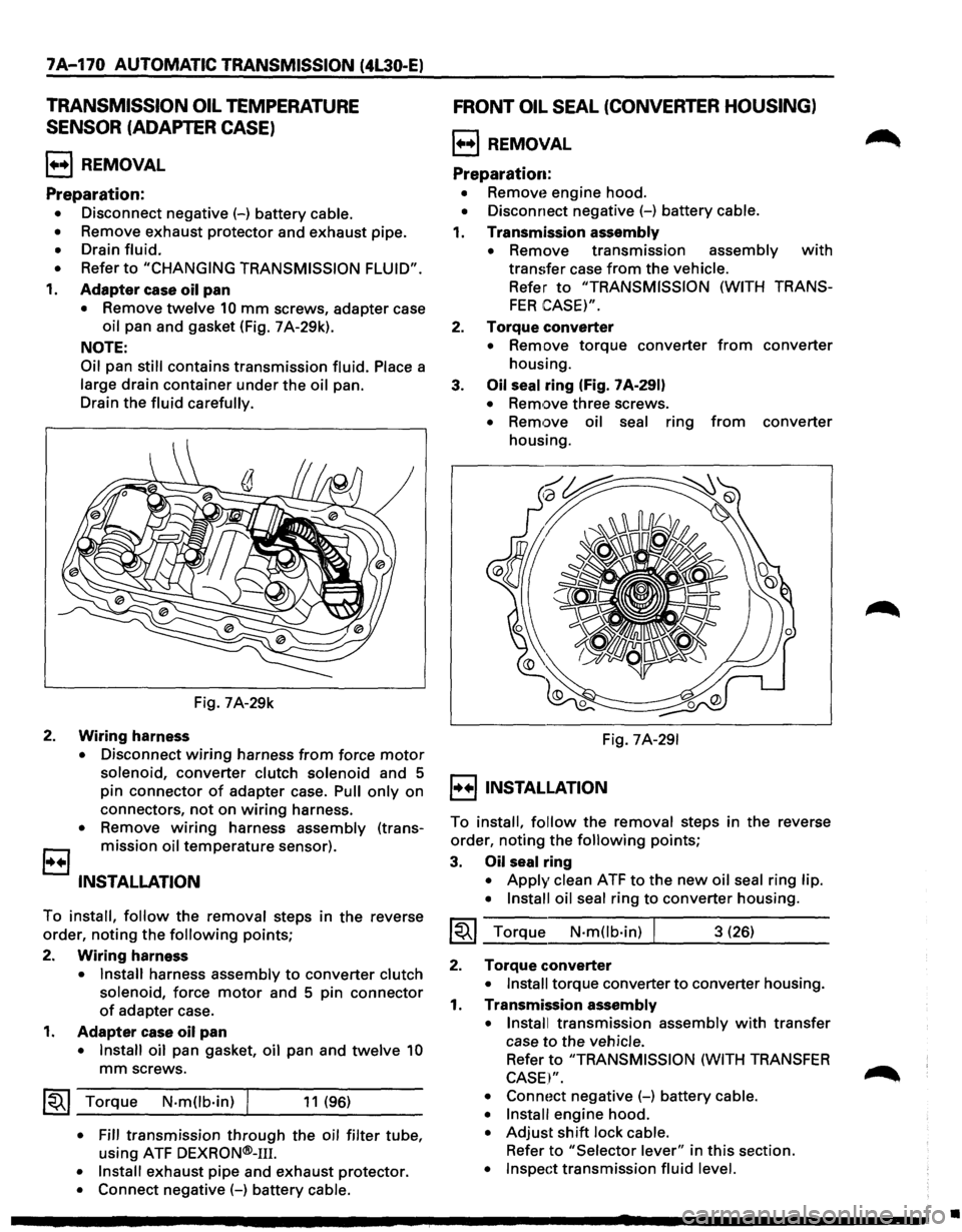
• Remove twelve 10 mm screws, adapter case
oil pan and gasket (Fig. 7 A-29k).
NOTE:
Oil
pan still contains transmission fluid. Place a
large drain container under the oil pan.
Drain the
fluid carefully.
Fig. 7A-29k
2. Wiring harness
• Disconnect wiring harness from force motor
solenoid, converter clutch solenoid and 5
pin connector
of adapter case. Pull only on
connectors,
not on wiring harness.
• Remove wiring harness assembly (trans
B mission oil temperature sensor).
INSTALLATION
To install, follow the removal steps in the reverse
order, noting the
following points;
2.
Wiring harness
• Install harness assembly to converter clutch
solenoid,
force motor and 5 pin connector
of adapter case.
1. Adapter case oil pan
• Install oil pan gasket, oil pan and twelve 10
mm screws.
~~~ Torque N·mOb·in) I 11 (96)
• Fill transmission through the oil filter tube,
using ATF
DEXRON®-111.
• Install exhaust pipe and exhaust protector.
• Connect negative (-) battery cable.
FRONT OIL SEAL (CONVERTER HOUSING)
l++l REMOVAL
Preparation:
• Removt~ engine hood.
• Disconnect negative (-) battery cable.
1. Transmission assembly
•
Remove transmission assembly with
transfer case from the vehicle.
Refer to "TRANSMISSION (WITH TRANS
FER CASE)".
2. Torque converter
• Remove torque converter from converter
housing.
3.
Oil seal ring (Fig. 7 A-291)
• Remove three screws.
• Remove oil seal ring from converter
housing.
Fig.
7A-291
I++IINSTALLATION
To install, follow the removal steps in the reverse
order, noting the
following points;
3. Oil seal ring
• Apply clean ATF to the new oil seal ring lip.
• Install oil seal
ring to converter housing.
~~~ Torque N·mOb·in) I 3 (26)
2. Torque converter
• Install torque converter to converter housing.
1. Transmission assembly
• Install
transmission assembly with transfer
case
to the vehicle.
Refer to "TRANSMISSION (WITH TRANSFER
CASE I".
• Connoct negative (-) battery cable.
• Install
engine hood.
• Adjust shift lock cable.
Refer to "Selector lever" in this section.
• Inspect transmission fluid level.
•
Page 1046 of 1928
7A-174 AUTOMATIC TRANSMISSION (4L30·E)
1•!•1 biSASSEMBLV
During the disassembly and reassembly of the
following components, perform the following:
• Wash each part thoroughly and blow air
through each oil passage and groove to
eliminate blockage.
• Seal rings, roll pins and gaskets should be
replaced
with new parts.
• When assembling the components, apply
DEXRON®-m Automatic Transmission Fluid
(ATF)
to each seal, rotating part and sliding
part.
• Do not dip those parts having a facing, such as
drive plate for clutch or brake, in the cleaner
when washing it with solvent.
Also, always wash
it with new ATF two or
three times after cleaning with solvent.
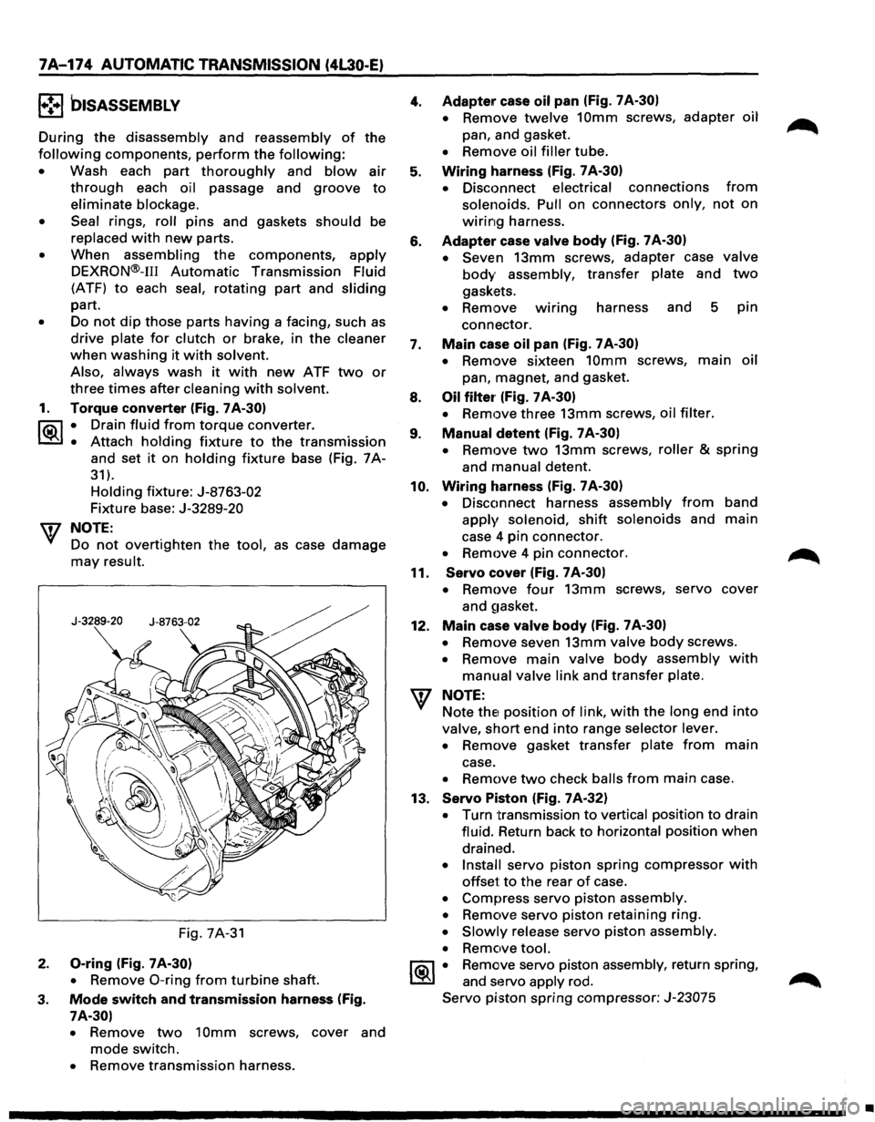
1. Torque converter (Fig. 7A-30)
l"i:\1 • Drain fluid from torque converter.
~ • Attach holding fixture to the transmission
and set it on holding fixture base (Fig. 7A-
31).
Holding fixture: J-8763-02
Fixture base: J-3289-20
w NOTE:
Do
not overtighten the tool, as case damage
may result.
Fig. 7A-31
2. 0-ring (Fig. 7 A-30)
•
Remove 0-ring from turbine shaft.
3. Mode switch and transmission harness (Fig.
7A-30)
•
Remove two 10mm screws, cover and
mode switch.
• Remove transmission harness.
4.
5.
6.
7.
8.
9.
10.
11.
12.
Adapter case oil pan (Fig. 7 A-30)
•
Remove twelve 10mm screws, adapter oil
pan, and gasket.
• Remove oil filler tube.
Wiring harness (Fig. 7 A-30)
•
Disconnect electrical connections from
solenoids. Pull on connectors only, not on
wiring harness.
Adapter case valve body (Fig. 7A-30)
• Seven
13mm screws, adapter case valve
body assembly, transfer plate and two
gaskets.
• Remove wmng harness and 5 pin
connector.
Main case oil pan (Fig. 7 A-30)
•
Remove sixteen 10mm screws, main oil
pan, magnet, and gasket.
Oil filter· (Fig. 7 A-30)
•
Remove three 13mm screws, oil filter.
Manual detent (Fig. 7 A-30)
•
Remove two 13mm screws, roller & spring
and manual detent.
Wiring harness (Fig. 7 A-30)
•
Disconnect harness assembly from band
apply solenoid, shift solenoids and main
case 4 pin connector.
• Remove 4 pin connector.
Servo cover (Fig. 7 A-30)
•
Remove four 13mm screws, servo cover
and
~1asket.
Main case valve body (Fig. 7 A-30)
•
Remove seven 13mm valve body screws.
• Remove main valve body assembly with
manual valve link and transfer plate.
NOTE: Note
thE! position of link, with the long end into
valve, short end into range selector lever.
• Remove gasket transfer plate from main
case.
• Remove two check balls from main case.
13.
Servo Piston (Fig. 7A-32)
• Turn transmission to vertical position to drain
fluid. Return back
to horizontal position when
drained.
• Install servo piston spring compressor with
offset to the rear of case.
• Compress servo piston assembly.
• Remove servo piston retaining ring.
• Slowly release servo piston assembly.
• Remove tool.
1®.1 • Remove servo piston assembly, return spring,
and servo apply rod.
Servo piston spring compressor: J-23075
•
Page 1049 of 1928
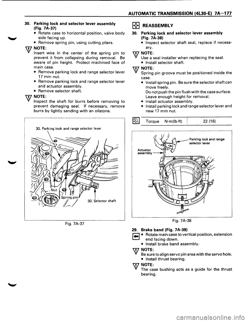
30. Parking lock and selector lever assembly
(Fig. 7A-37)
• Rotate case to horizontal position, valve body
side facing up.
• Remove spring pin, using cutting pliers.
\fl NOTE:
~ Insert wire in the center of the spring pin to
prevent it from collapsing during removal. Be
aware of pin height. Protect machined face of
main case.
• Remove parking lock and range selector lever
17 mm nut.
• Remove parking lock and range selector lever
and actuator assembly.
•
Remove selector shaft.
\fl NOTE:
~ Inspect the shaft for burrs before removing to
prevent damaging seal. If necessary, remove
burrs
by lightly sanding with an oilstone.
30. Parking lock and range selector lever
30. Selector
shaft
Fig. 7A-37
AUTOMATIC TRANSMISSION (4L30-E) 7A-177
1 .. ! .. 1 REASSEMBLY
30. Parking lock and selector lever assembly
(Fig. 7A-38)
• Inspect selector shaft seal, replace if necess
ary.
\fl NOTE:
~ Use a seal installer when replacing the seal.
• Install selector
shaft.
\fl NOTE:
~ Spring pin groove must be positioned inside the
case.
• Install spring pin. Be sure the selector shaft can
move
freely.
Do not push the pin flush with the case surface.
Leave enough
height for removal.
• Install
actuator assembly.
• Install
parking lock and range selector lever and
new 17 mm nut.
~~~ Torque N·m(lb·ft) 22 (16)
Parking lock and range selector lever
Fig. 7A-38
29. Brake band (Fig. 7A-39)
~ • Rotate main case to vertical position, extension
~ end facing down.
• Install brake band assembly.
\fl NOTE:
~ Be sure to align servo pin area with the servo hole.
• Install
thrust bearing.
\fl NOTE:
~ The case bushing acts as a guide for the thrust
bearing.
Page 1055 of 1928
~~11. Fourth •
~ clutch
___,,.,.,.,.
retainer
Turbine shaft
& overrun clutch
housing assembly
Fourth clutch
plates
®• I 19. Thrust bearing
18
~Overdrive L' ,
~ernal gear _ ------_j
~ 2l. Thr~st washer
Fig. 7A-50
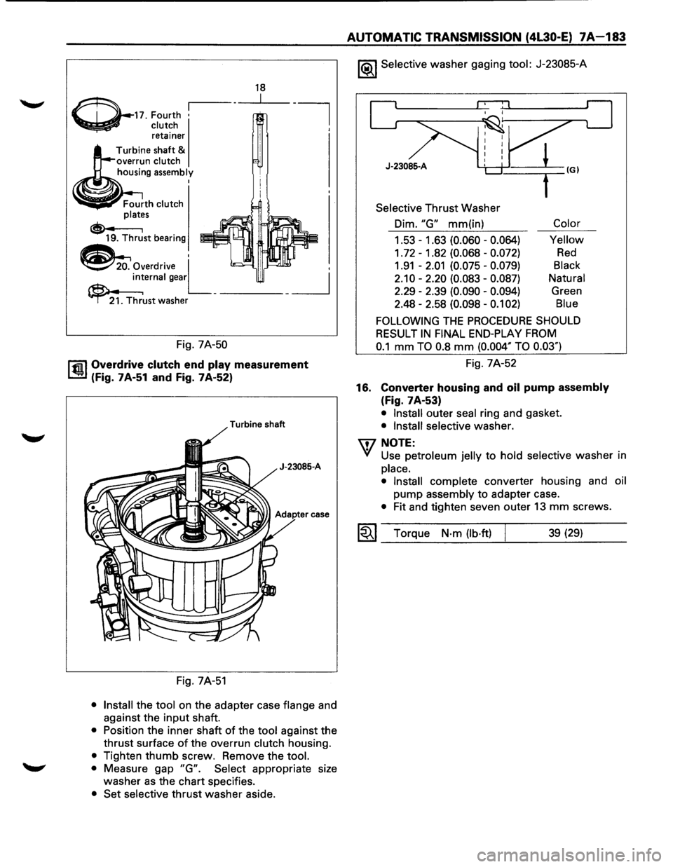
rfi:il Overdrive clutch end play measurement
~ (Fig. 7A-51 and Fig. 7A-52)
Turbine shaft
J-23085-A
case
Fig. 7A-51
• Install the tool on the adapter case flange and
against the
input shaft.
• Position the inner shaft of the tool against the
thrust surface
of the overrun clutch housing.
• Tighten thumb screw. Remove the tool.
• Measure gap "G". Select appropriate size
washer
as the chart specifies.
• Set selective thrust washer aside.
AUTOMATIC TRANSMISSION (4L30-E) 7A-183
1®.1 Selective washer gaging tool: J-23085-A
J-23085-A
Selective Thrust Washer
Dim.
"G" mm(in) Color
1.53-1.63 (0.060- 0.064) Yellow
1. 72 - 1 .82 (0.068 -0.072) Red
1.91 -2.01 (0.075 -0.079) Black
2.10-2.20 (0.083-0.087) Natural
2.29 -2.39
(0.090 -0.094) Green
2.48 -2.58
(0.098 -0.1 02) Blue
FOLLOWING THE PROCEDURE SHOULD
RESULT
IN FINAL END-PLAY FROM
0.1 mm TO 0.8 mm (0.004" TO 0.03")
Fig. 7A-52
16.
Converter housing and oil pump assembly
(Fig. 7A-53)
• Install outer seal ring and gasket.
• Install selective washer.
W NOTE:
VI Use petroleum jelly to hold selective washer in
place.
• Install
complete converter housing and oil
pump
assembly to adapter case.
• Fit and tighten seven outer 13 mm screws.
~~~ Torque N·m (lb·ft) j 39 (29)
Page 1056 of 1928
7A-184 AUTOMATIC TRANSMISSION (4L30-E)
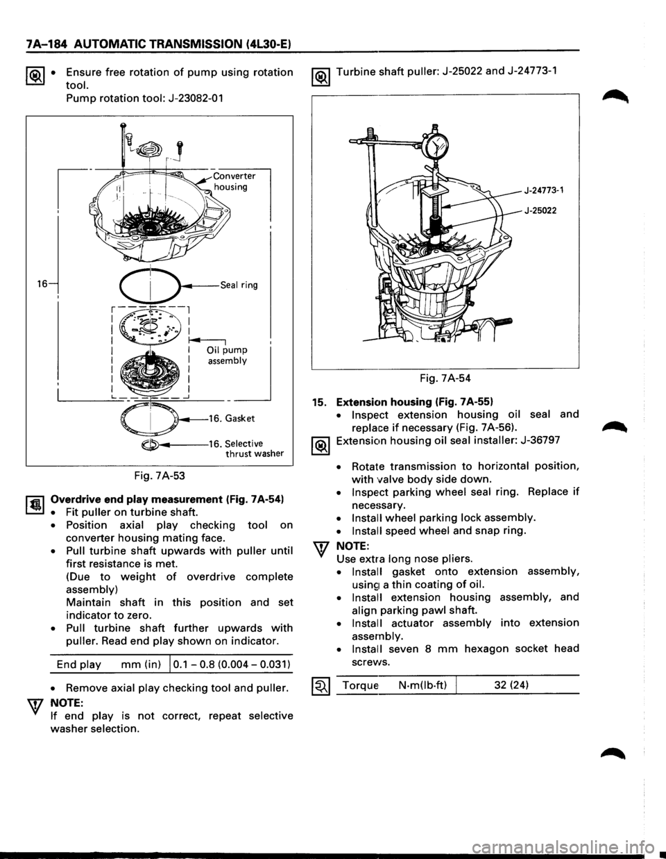
~· Ensure free rotation of pump using rotation
tool.
16
Pump rotation tool: J-23082-01
-----16. Selective thrust washer
Fig. 7A-53
l'fil Overdrive end play measurement (Fig. 7A-54)
~ • Fit puller on turbine shaft.
• Position axial play checking tool on
converter housing mating face.
• Pull turbine shaft upwards with puller until
first resistance is met.
(Due
to weight of overdrive complete
assembly)
Maintain shaft in this position and set
indicator to zero.
• Pull turbine shaft further upwards with
puller. Read end play shown on indicator.
End
play mm (in) I 0.1 -0.8 (0.004-0.031)
1®.1 Turbine shaft puller: J-25022 and J-24773-1
J-24773·1
J-25022
Fig. 7A-54
15. Extension housing (Fig. 7A-55)
• Inspect extension housing oil seal and
replace if necessary (Fig. 7 A-56).
1®.1 Extension housing oil seal installer: J-36797
• Rotate transmission to horizontal position,
with valve body side down.
• Inspect parking wheel seal ring. Replace if
necessary.
• Install wheel parking lock assembly.
• Install
speed wheel and snap ring.
NOTE:
Use extra long nose pliers.
• Install
gasket onto extension assembly,
usin£1 a thin coating of oil.
• Install
extension housing assembly, and
align parking pawl shaft.
• Install actuator assembly into extension
assembly.
• Install
seven 8 mm hexagon socket head
screws.
• Remove axial play checking tool and puller. ~~~ Torque N-m(lb.ft) 32 (24) W NOTE: _ __:_ ___ __:___:__J_ _ __.::..:::....=_:..:.__ __
If end play is not correct, repeat selective
washer selection.
Page 1057 of 1928
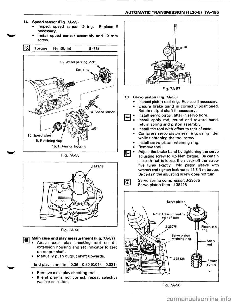
14. Speed sensor (Fig. 7A-55)
• Inspect speed sensor 0-ring. Replace if
necessary.
~ • Install speed sensor assembly and 10 mm
screw.
~~~ Torque N-m(lb-in) 9 (78)
15. Wheel parking lock
15. Retaining ring
15. Extension housing
Fig. 7A-55
J-36797
Fig. 7A-56
rfil Main case end play measurement (Fig. 7A-57)
~ • Attach axial play checking tool on the
extension housing and set indicator to zero
on
output shaft.
• Manually push output shaft upwards.
End play mm (in) 10.36-0.80 (0.014-0.031)
• Remove axial play checking tool.
• If end play is not correct, repeat selective
washer selection.
AUTOMATIC TRANSMISSION (4l30-E) 7A-185
Fig. 7A-57
13. Servo piston (Fig. 7A-58)
•
•
8:
•
•
•
•
[E•
Inspect piston seal ring. Replace if necessary .
Ensure brake band is correctly
positioned .
Rotate
output shaft if necessary.
Install servo piston fitter in servo bore.
Install apply rod, round end toward band,
return
spring and piston assembly.
Install the tool with offset to rear of case .
Compress servo
piston seal ring, using fitter
while tightening the tool screw.
Install servo piston retaining ring .
Remove
tool.
Adjust the brake band by tightening the servo
adjusting screw
to 4.5 N-m torque. Be certain
the lock nut
is loose, then back-off the screw
five turns exactly. Hold piston sleeve with
wrench and tighten lock nut to
18.5 N-m torque.
Be certain the adjusting screw does not turn.
Servo
spring compressor: J-23075
Servo piston fitter: J-38428
Servo piston
Note: Offset
of tool to rear of case
Servo piston
retaining ring
J-38428
Fig. 7A-58
~~--Return spring
Page 1059 of 1928
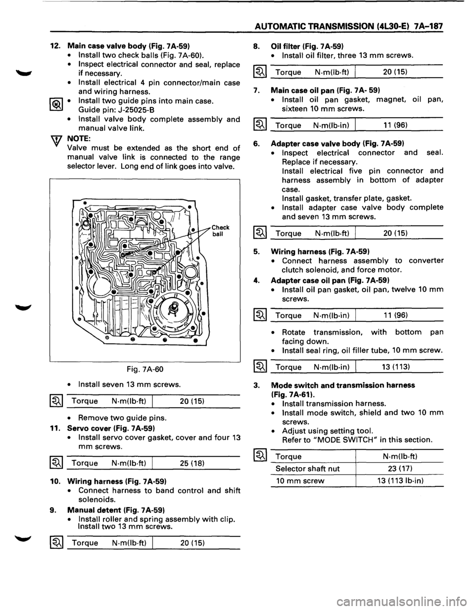
12. Main case valve body (fig. 7A-59)
• Install two check balls (Fig. 7A-60).
• Inspect electrical
connector and seal, replace
if necessary.
• Install electrical 4 pin connector/main case
and
wiring harness.
1®..1 • Install two guide pins into main case.
Guide pin:
J-25025-B
• Install valve
body complete assembly and
manual valve link.
W NOTE:
Valve must be extended as the short end of
manual valve link is connected to the range
selector lever. Long end of link goes into valve.
Fig. 7A-60
• Install
seven 13 mm screws.
~~~ Torque N·mOb·ft) I 20 (15)
• Remove two guide pins.
11.
Servo cover (fig. 7 A-59)
Check ball
• Install servo cover gasket, cover and four 13
mm screws.
~~~ Torque N·mOb·ft) I 25 ( 18)
10. Wiring harness (fig. 7A-59)
• Connect harness to band control and shift
solenoids.
9. Manual detent (fig. 7 A-59)
• Install roller and spring assembly with clip.
Install two 13 mm screws.
~~~ Torque N·mOb·ft) 20 (15)
AUTOMATIC TRANSMISSION (4L30-E) 7A-187
8. Oil filter (Fig. 7 A-59)
• Install oil filter, three 13 mm screws.
~~~ Torque N.m(lb·ft) I 20 (15)
7. Main
case oil pan (Fig. 7 A- 59)
• Install oil pan gasket, magnet, oil pan,
sixteen
10 mm screws.
~~~ Torque N·m(lb·in) I 11 (96)
6. Adapter case valve body (fig. 7 A-59)
• Inspect electrical connector and seal.
Replace
if necessary.
Install electrical five pin connector and
harness
assembly in bottom of adapter
case.
Install gasket, transfer plate, gasket.
• Install adapter case valve body complete
and seven 13 mm screws.
~~~ Torque N.m(lb.ft) I 20 (15)
5. Wiring harness (fig. 7A-59)
• Connect harness assembly to converter
clutch solenoid, and force motor.
4. Adapter case oil pan (fig. 7 A-59)
• Install oil pan gasket, oil pan, twelve 10 mm
screws.
~~~ Torque N·mOb·in) 11 (96)
• Rotate transmission, with bottom pan
facing
down.
• Install seal ring, oil filler tube, 10 mm screw.
~~~ Torque N·mOb·in) I 13 (113)
3. Mode switch and transmission harness
(Fig. 7A-61).
• Install transmission harness.
• Install mode switch, shield and two 10 mm
screws.
• Adjust using setting tool.
Refer to "MODE SWITCH" in this section.
~~~ Torque
Selector shaft nut
10 mm screw
N·mOb·ft)
23 (17)
13 (113 lb·in)