torque ISUZU TROOPER 1995 Workshop Manual
[x] Cancel search | Manufacturer: ISUZU, Model Year: 1995, Model line: TROOPER, Model: ISUZU TROOPER 1995Pages: 1928
Page 1060 of 1928
7A-188 AUTOMATIC TRANSMISSION (4L30-E)
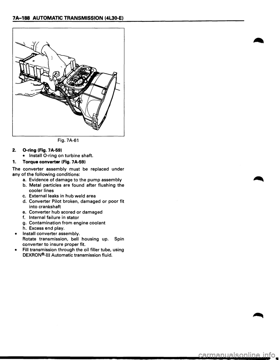
Fig. 7A-61
2. 0-ring (fig. 7 A-59)
• Install 0-ring on turbine shaft.
1. Torque converter
(fig. 7A-59)
The converter assembly
must be replaced under
any
of the following conditions:
a. Evidence of damage to the pump assembly
b. Metal particles are found after flushing
the
cooler lines
c. External leaks in hub weld area
d. Converter Pilot broken, damaged
or poor fit
into crankshaft
e. Converter hub scored or damaged
f.
Internal failure in stator
g. Contamination
from engine coolant
h. Excess end play.
• Install converter assembly.
Rotate transmission,
bell housing up. Spin
converter
to insure proper fit.
• Fill transmission through the oil filler tube, using
DEXRQN®-111 Automatic transmission fluid.
Page 1061 of 1928
AUTOMATIC TRANSMISSION (4L30·E) 7A-189
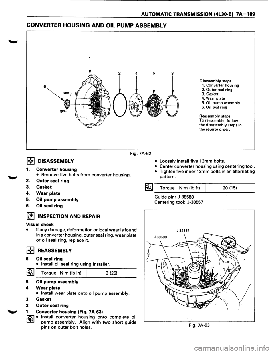
CONVERTER HOUSING AND OIL PUMP ASSEMBL V
1
Disassembly steps
1. Converter housing
2. Outer seal ring
3. Gasket
4. Wear
plate
5. Oil pump assembly
6. Oil seal ring
Reassembly steps
To reassemble, follow
the disassembly steps in the reverse order.
Fig. 7A-62
l•!•l DISASSEMBLY
1. Converter housing
• Remove five bolts from converter housing.
2. Outer seal ring
3. Gasket
4. Wear plate
5. Oil pump assembly
6. Oil seal ring
[1!) INSPECTION AND REPAIR
Visual check
• If any damage, deformation or local wear is found
in a converter housing, outer
seal ring, wear plate
or oil seal ring, replace it.
l•!•l REASSEMBLY
6. Oil seal ring
• Install oil seal ring using installer.
1~1 Torque N·m (lb·in)
5. Oil pump assembly
4. Wear plate
3 (26)
• Install wear plate onto oil pump assembly.
3. Gasket
2. Outer seal ring
"-"' 1. Converter housing (Fig. 7A-63)
li0\1 • Install converter housing onto complete oil
~ pump assembly. Align with two short guide
pins on outer
bolt holes. •
Loosely install
five 13mm bolts.
•
Center converter housing using centering tool.
•
Tighten five inner 13mm bolts in an alternating
pattern.
I~I ___ T_o_rq~u_e __ N_·_m_(_lb_·ft_)~l _____ 2_0_(_15_) ____ _
Guide pin: J-38588
Centering
tool: J-38557
J-38557
Fig. 7A-63
Page 1064 of 1928
7A 192 AUTOMATIC TRANSMISSION (4L30-E)
l•!•l REASSEMBL V
27. Check ball
• Install
1 check ball to valve body
26. 1-2
accumulator control valve
25. 1-2 accumulator valve
24. Plug
23. Spring pin
22. Band
control screen assembly
21. Plug
20.
Spring pin
19.
Low pressure control valve
18. Spring
17. Plug
16. Spring pin
15.
Spring
14. 2-3 shift valve
13.
Retainer
12. 2-3
solenoid
11. Spring pin
10. Spring
9. 1-2/3-4 shift valve
8. Retainer
7. 1-2/3-4 solenoid
6. Spring pin
5. Waved washer
4. Pin
3. Band control solenoid
2. Manual valve
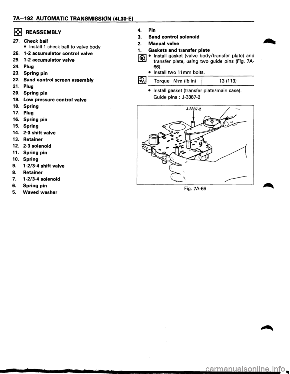
1. Gaskets and transfer plate
li5\l • Install gasket (valve body/transfer plate) and
~ transfer plate, using two guide pins (Fig. 7A-
66).
• Install two 11 mm bolts.
1~1 Torque N·m (lb·in) j 13 (113)
• Install gasket (transfer plate/main case).
Guide pins :
J-3387-2
Fig. 7A-66
Page 1066 of 1928
7A-194 AUTOMATIC TRANSMISSION (4L30-E)
f•!•l REASSEMBLY
15. Force motor screen assembly
14. Plug
13. 0-ring
12. Spring pin
11. Feed
limit valve
10. Retaining ring
9. Spring
8. Spring pin
7. 3/4 accumulator control valve
6. 3/4 accumulator valve
5. Plug
4. Spring pin
3. Force motor solenoid
2. Retainer
r=1 • Plac_e solenoid terminals pointing towards
1=.1 matmg face.
• Install retainer and bolt.
~~~ Torque N·m (lb·in) I 10 (87)
1. Converter clutch solenoid
• Install converter clutch solenoid assembly with
two 0-rings to valve body.
• Install bolt.
~~~ Torque N·m (lb·in) I 10 (87)
Page 1075 of 1928
1 .. !•1 REASSEMBL V
13. Overrun lock out valve
........,
12. Spring
• Install overrun lock out valve and spring.
\fJ NOTE:
VI Ensure correct assembly of valve. The spring
should be located over the long small diameter
end.
11. Plug
10.
Pin
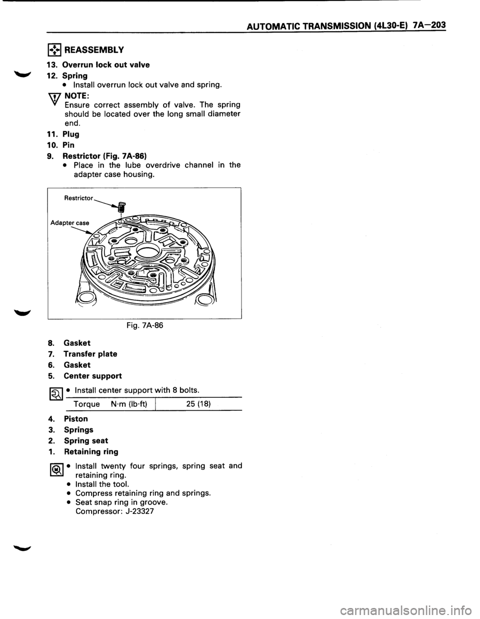
9. Restrictor (Fig. 7A·86)
• Place in the lube overdrive channel in the
adapter case housing.
8. Gasket
7. Transfer plate
6. Gasket
5. Center support
Fig. 7A-86
~~~· Install center support with 8 bolts.
Torque N·m (lb·ft) I 25 (18)
4. Piston
3. Springs
2. Spring seat
1. Retaining ring
1®.1• Install twenty four springs, spring seat and
retaining ring.
• Install the tool.
•
Compress retaining ring and springs.
• Seat snap ring in groove.
Compressor: J-23327
AUTOMATIC TRANS.MISSION (4L30-E) 7A-203
Page 1079 of 1928
AUTOMATIC TRANSMISSION (4L30-E) 7 A-207
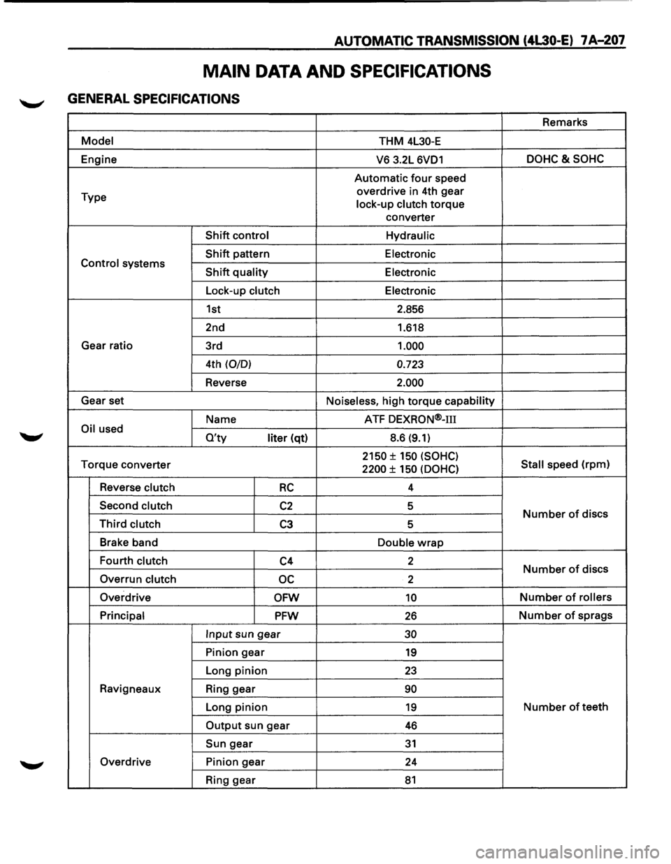
MAIN DATA AND SPECIFICATIONS
GENERAL SPECIFICATIONS
Remarks
Model THM 4L30-E
Engine
V6 3.2L 6VD1 DOHC&SOHC
Automatic four speed
Type overdrive
in 4th gear
lock-up clutch
torque
converter
Shift control Hydraulic
Shift pattern
Electronic Control systems Shift quality Electronic
Lock-up clutch Electronic
1st 2.856
2nd 1.618
Gear ratio
3rd
1.000
4th (0/0) 0.723
Reverse 2.000
Gear set
Noiseless, high torque capability
Name ATF
DEXRON®-m
Oil used O'ty liter (qt) 8.6 (9.1)
Torque
converter 2150 ± 150 (SOHC)
Stall speed (rpm) 2200 ± 150 (OOHC)
Reverse clutch RC 4
Second clutch
C2 5 Number of discs Third clutch C3 5
Brake band
Double
wrap
Fourth clutch C4 2 Number of discs
Overrun clutch oc 2
Overdrive
OFW 10 Number of rollers
Principal
PFW 26 Number of sprags
Input sun gear 30
Pinion gear 19
Long pinion 23
Ravigneaux Ring gear 90
Long pinion 19 Number of teeth
Output sun gear 46
Sun gear 31
Overdrive Pinion gear
24
Ring gear
81
Page 1080 of 1928
7 A-208 AUTOMATIC TRANSMISSION (4l30-E)
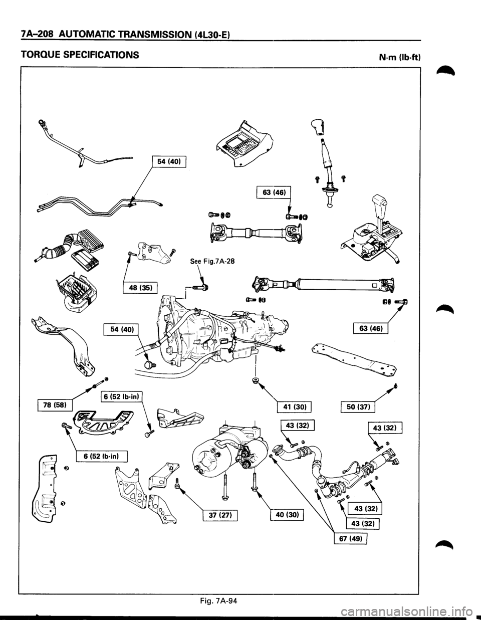
TORQUE SPECIFICATIONS
•
/r6 (52 lb·in)
~-L
~
Fig. 7A-94
N-m (lb-ft)
'
o;
JJI/
~
Page 1081 of 1928
AUTOMATIC TRANSMISSION (4L30-E) 7A-209
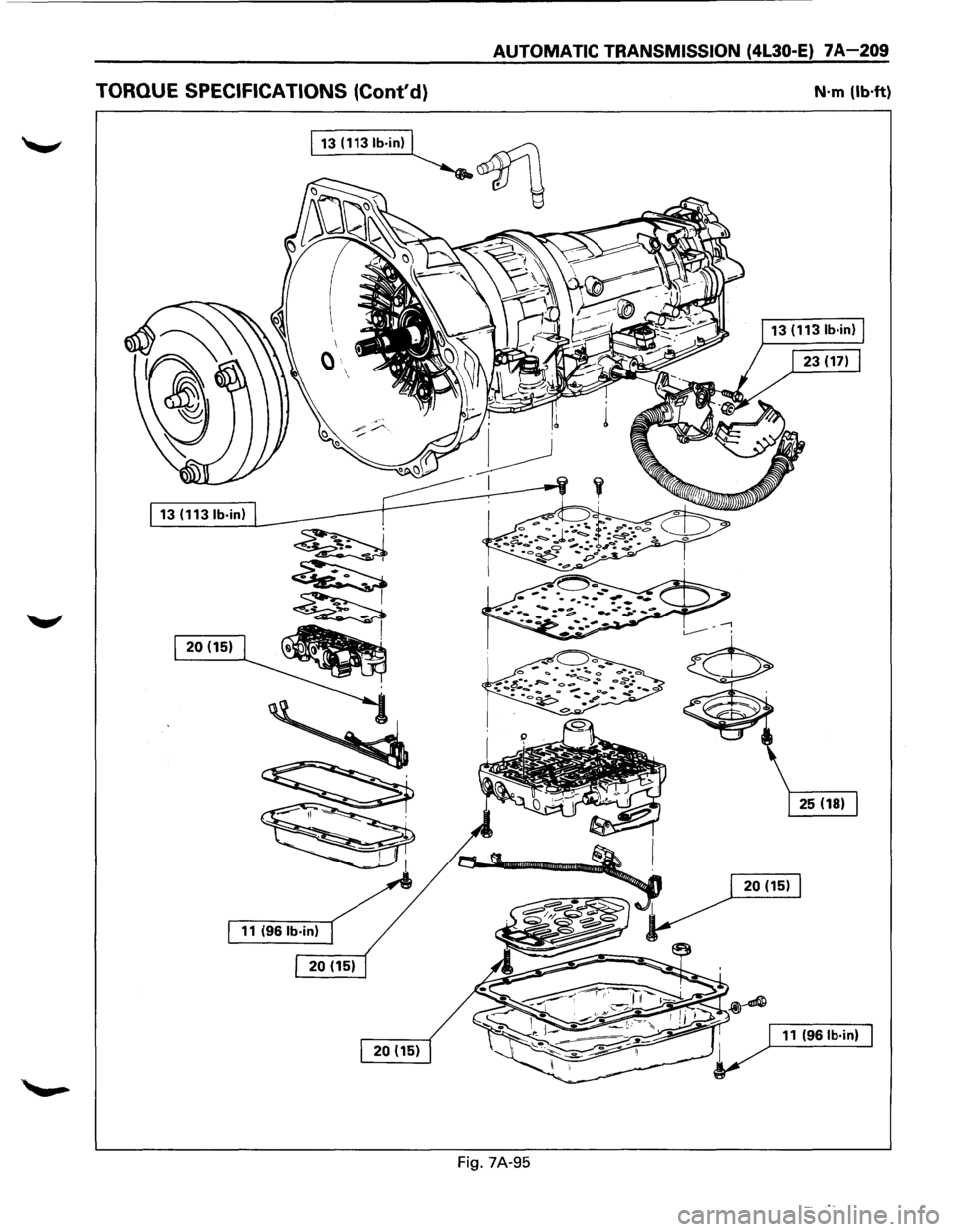
TORQUE SPECIFICATIONS (Cont'd} N·m (lb·ft)
13 (1131b·in)
~
~
120(1511~
·~
Fig. 7A-95
Page 1082 of 1928
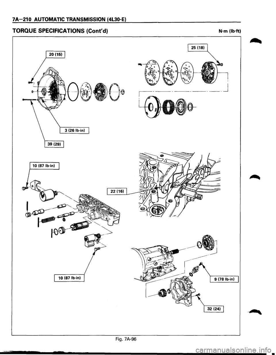
7A-210 AUTOMATIC TRANSMISSION (4L30-E)
TORQUE SPECIFICATIONS (Cont'd) N·m (lb·ft)
______ j
10 (87 lb·in)
10
(87 lb·in) 9 (78 lb·in)
Fig. 7A-96
Page 1086 of 1928
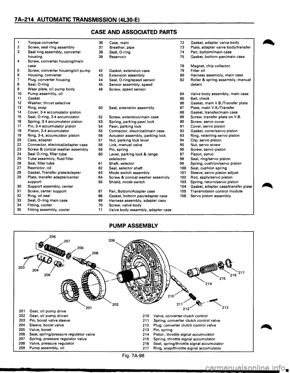
7A-214 AUTOMATIC TRANSMISSION (4L30-E)
CASE AND ASSOCIATED PARTS
1 Torque converter 2 Screw, seal ring assembly 3 Seal ring assembly, converter
housing
4 Screw, converter housing/main
case
5 Screw, converter housing/oil pump 6 Housing, converter 7 Plug, converter housing 8 Seal, 0-ring 9 Wear plate, oil pump body 10 Pump assembly, oil 11 Gasket 12 Washer, thrust selective 13 Ring, snap 14 Cover, 3-4 accumulator piston 15 Seal, 0-ring, 3-4 accumulator 16 Spring, 3-4 accumulator piston 17 Pin, 3-4 accumulator piston 18 Piston, 3-4 accumulator 19 Ring, 3-4, accumulator piston 20 Case, adapter 22 Connector, electrical/adapter case 23 Screw & conical washer assembly 24 Seal 0-ring, filler tube 25 Tube assembly, fluid filler 26 Seal, filler tube 27 Restrictor, oil 28 Gasket, Transfer plate/adapter 29 Plate, transfer adapter/center
support
30 Support assembly, center 31 Screw, center support 32 Ring, oil seal
33 Seal, 0-ring main case 34 Fitting, cooler 35 Fitting assembly, cooler
206
201 Gear, oil pump drive 202 Gear, oil pump driven 203 Pin, boost valve sleeve 204 Sleeve, boost valve 205 Valve, boost
201
206 Seat, spring/pressure regulator valve 207 Spring, pressure regulator valve 208 Valve, pressure regulator 209 Pump assembly, oil
36 37
38
39
42 43
44
45
46
50
52
53
54
55
56
57
58 59
60
61
62 63 64
65
67
68 69 70 71
Case, main 72 Gasket, adapter valve body
Breather, pipe 73 Plate, adapter valve body/transfer
Seal, 0-ring 74 Pan, bottom/main case
Reservoir
75 Gasket, bottom pan/main case
78 Magnet, chip collector
Gasket, extension case
79 Filter oil
Extension assembly
80 Harness assembly, main case
Seal, 0-ring/speed sensor 82 Roller & spring assembly, manual
Sensor assembly, speed detent Screw, speed
sensor 84 Valve body assembly, main case
85 Ball, check
86 Gasket, main V.B./Transfer plate
Seal, extension assembly 87 Plate, main V.B./Transfer
88 Gasket, transfer/main case
Screw, extension/main case 89 Screw, transfer plate on V.B.
Spring, parking pawl lock 90 Screw, servo cover
Pawl, parking lock 91 Cover, servo piston Connector, electrical/main case 92 Gasket, cover/servo piston
Actuator assembly, parking lock
93 Ring, retaining servo piston
Nut, parking lock lever 94 Clip, servo piston
Link, manual valve 95 Nut, servo screw
Pin, spring 96 Screw, servo piston
Lever, parking lock
& range 97 Piston, servo
selelector 98 Seal, ring/servo piston
Shaft, selector 99 Spring, cushion/servo piston
Seal, selector shaft 100 Seat, cushion spring
Mode switch assembly 101 Sleeve, servo piston adjust
Screw & conical washer assembly 102 Rod, apply/servo piston
Shield, mode switch 103 Spring, return/servo piston 104 Gasket, adapter case/transfer plate
Pan, Bottom/Adapter case 105 Transmission control module
Gasket,
bottom pan/adapter ca!~e 106 Servo piston assembly
Harness assembly, adapter
cas'~ Screw, valve body
Valve body assembly, adapter ~:ase
PUMP ASSEMBLY
202 211 ~-~ 212 . 213
210 Valve, converter clutch control 211 Sprinn, converter clutch control valve 212 Plug, converter clutch control valve 213 Pin, spring 214 Piston, throttle signal accumulator 215 Sprinn, throttle signal accumulator 216 Seat, 1;pring/throttle signal accumulator 217 Ring, snap/throttle signal accumulator
Fig. 7A-98
~
•