lock ISUZU TROOPER 1995 Repair Manual
[x] Cancel search | Manufacturer: ISUZU, Model Year: 1995, Model line: TROOPER, Model: ISUZU TROOPER 1995Pages: 1928
Page 229 of 1928
PROPELLER SHAFT 4A-1
SECTION 4A
PROPELLER SHAFT AND AXLE
CONTENTS
Propeller Shaft . . . . . . . . . . . . . . . . . . . . . . . . . . . . . . . . . . . . . . . . . . . . . . . . . . . . . . . . . . . . . . . . . . Section 4A
Rear Axle . . . . . . . . . . . . . . . . . . . . . . . . . . . . . . . . . . . . . . . . . . . . . . . . . . . . . . . . . . . . . . . . . . . . . . . Section 48
Front Driving Axle . . . . . . • . . . . . . . . . . . . . . . . . . . . . . . . . . . . . . . . . . . . . . . . . . . . . . . . . . . . . . . . Section 4C
SECTION 4A
PROPELLER SHAFT
\fl CAUTION:
VI When fasteners are removed, always reinstall them at the same location from which they were removed. If a
fastener needs
to be replaced, use the correct part number fastener for that application. If the correct part
number fastener is
not available, a fastener of equal size and strength (or stronger) may be used. Fasteners
that are
not reused, and those requiring thread locking compound, will be called out. The correct torque
values must be used when installing fasteners that require torque. If the above conditions are not followed, •
parts or system damage could result.
CONTENTS
General Description . . . . . . . . . . . . . . . . . . . . . 4A-1
On-Vehicle Service . . . . . . . . . . . . . . . . . . . . . 4A-2
Rear
Propeller Shaft . . . . . . . . . . . . . . . . . . 4A-2
Front Propeller Shaft . . . . . . . . . . . . . . . . . . 4A-3
Unit Repair ............................ 4A-4
Rear
Propeller Shaft . . . . . . . . . . . . . . . . . . 4A-4
Universal Joint (Rear Propeller Shaft) .... 4A-5
Front Propeller Shaft .................. 4A-8
Universal Joint (Front Propeller Shaft) ... 4A-9
Main Data and Specifications ............ 4A-12
General Specifications ................ 4A-12
Torque Specifications ................ 4A-13
GENERAL DESCRIPTION
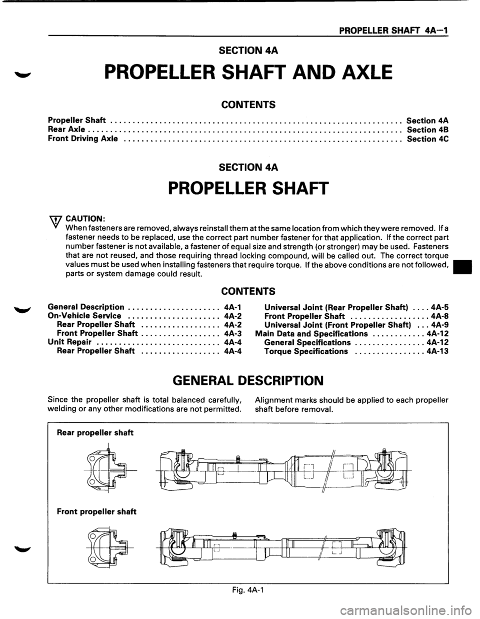
Since the propeller shaft is total balanced carefully,
welding
or any other modifications are not permitted.
Rear
propeller shaft
Front propeller shaft
Alignment marks should be applied to each propeller
shaft before removal.
Fig. 4A-1
Page 234 of 1928
4A-6 PROPELLER SHAFT
IL•IINSPECTION
AND REPAIR
Make necessary correction or parts replacement if
wear, damage,corrosion or any other abnormal
condition is found through inspection.
NOTE:
When any part of the journal assembly (spider,
needle roller bearing, grease fitting) requires
replacement, be sure to replace the entire assembly.
Visual check
Check the following parts for wear, damage, noise or
any other abnormal conditions.
• Spider
• Needle roller bearing
• Yoke
• Flange
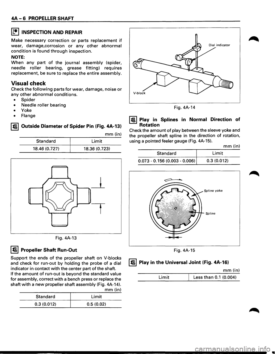
I til Outside Diameter of Spider Pin (fig. 4A-13)
mm (in)
Standard
18.46 (0.727)
Fig. 4A-13
I tJ I Propeller Shaft Run-Out
Limit
18.36 (0.723)
Support the ends
of the propeller shaft on V-blocks
and check for run-out by holding the probe of a dial
indicator in contact with the center part of the shaft.
If the amount of run-out is beyond the standard value
for assembly, correct with a bench press or replace the
shaft
with a new propeller shaft assembly (Fig. 4A-14).
mm (in)
Standard
Limit
0.3 (0.012) 0.5 (0.02) Fig.
4A-14
ltil Play in Splines in Normal Direction of
Rotation
Check the amount of play between the sleeve yoke and
the
propeller shaft spline in the direction of rotation,
using a pointed
feeler gauge (Fig. 4A-15).
mm(in)
Standard Limit
0.073 -0.156 (0.003 -0.006) 0.3
(0.012)
Spline yoke
Spline
Fig. 4A-15
I til Play in the Universal Joint (fig. 4A-16)
mm (in)
Limit Less than 0.1 (0.004)
..
Page 238 of 1928
4A -10 PROPELLER SHAFT
I L•IINSPECTION AND REPAIR
Make necessary correction or parts replacement if
wear, damage,corrosion or any other abnormal
condition is found through inspection.
NOTE:
When any part of the journal assembly (spider,
needle roller bearing) requires replacement, be sure
to replace the entire assembly.
Visual Check
Check the following parts for wear, damage, noise or
any other abnormal conditions.
• Spider
• Needle roller bearing
• Yoke
• Flange
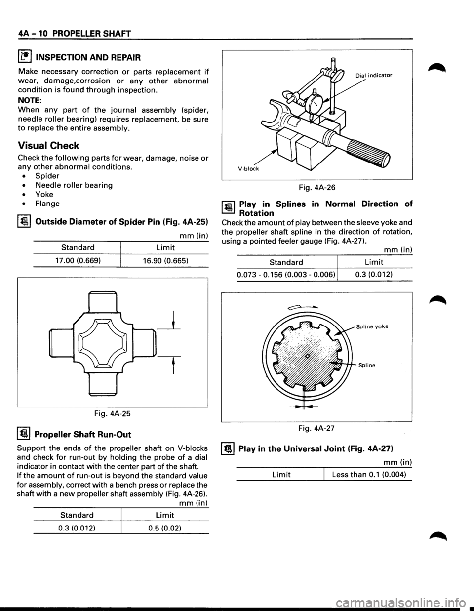
I til!, I Outside Diameter of Spider Pin (Fig. 4A-25)
mm(in)
Standard
17.00 (0.669)
Fig. 4A-25
I til!. I Propeller Shaft Run-Out
Limit
16.90 (0.665)
Support the ends of the propeller shaft on V-blocks
and check for run-out by holding the probe of a dial
indicator in contact with the center part of the shaft.
If the amount of run-out is beyond the standard value
for assembly, correct with a bench press or replace the
shaft
with a new propeller shaft assembly (Fig. 4A-26).
mm(in)
Standard Limit
0.3 (0.012)
0.5 (0.02)
V·block
Fig. 4A-26
1 til!, 1 Play in Splines in Normal Direction of
Rotation
Check the amount of play between the sleeve yoke and
the
propeller shaft spline in the direction of rotation,
using a pointed
feeler gauge (Fig. 4A-27).
mm (in)
Standard
Limit
0.073 - 0.156 (0.003 -0.006) 0.3 (0.012)
Spline yoke
Fig.
4A-27
ltil!.l Play in the Universal Joint (Fig. 4A-27)
mm (in)
Limit Less than 0.1 (0.004)
Page 243 of 1928
REAR AXLE 48-1
SECTION 48
REAR AXLE
\V CAUTION:
When fasteners are removed, always reinstall them at the same location from which they were removed.
If a fastener needs to be replaced, use the correct part number fastener for that application. If the correct
part number fastener is not available, a fastener of equal size and strength (or stronger) may be used.
Fasteners
that are not reused, and those requiring thread locking compound, will be called out. The
correct
torque values must be used when installing fasteners that require torque. If the above conditions
are not followed, parts or system damage could result.
CONTENTS
General Description . . . . . . . . . . . . . . . . . . . . 48-1
Diagnosis of Rear
Axle Noise . .
. . . . . . . . . . 48-3
On-Vehicle Service ..................... 48-4
Axle Housing . .
. . . . . . . . . . . . . . . . . . . . . 48-4
Axle Shaft . .
. . . . . . . . . . . . . . . . . . . . . . . . 48-7
Pinion
Oil Seal . .
. . . . . . . . . . . . . . . . . . . .
48-10
Differential Assembly
. .
. . . . . . . . . . . . . . 48-11 Unit
Repair . . . . . . . . . . . . . . . . . . . . . . . . . . . 48-13
Differential Assembly . .
. . . . . . . . . . . . . .
48-13 Differential Cage Assembly . . . . . . . . . . . . 48-23
Limited
Slip Differential . .
. . . . . . . . . . . . 48-27
Main Data and Specifications . . . . . . . . . . . . 48-33
General Specifications . .
. . . . . . . . . . . . . . 48-33
Torque Specifications
................ 48-34
Special Tools ......................... 48-35
GENERAL DESCRIPTION
The rear axle assembly is of the semi-floating type in
which the vehicle weight is carried on the axle
housing (Fig. 48-1).
The center
line of the pinion gear is below the center
line of the ring gear (hypoid drive).
All parts necessary to transmit power from the
propeller shaft to the rear wheels are enclosed in a
banjo type axle housing.
The 8.7 inch ring gear rear axle uses a conventional
ring and
pinion gear set to transmit the driving force
of the engine to the rear wheels. This gear set transfers
this driving force at a 90 degree angle from the
propeller shaft to the drive shafts. The
axle shafts
are supported at the wheel end of the
shaft by a roller bearing.
The
pinion gear is supported by two tapered roller
bearings. The pinion depth is set by a shim pack
located between the gear end of the pinion and the
roller bearing that is pressed onto the pinion. The
pinion bearing preload is set by crushing a collapsible
spacer between the bearings in the axle housing.
Page 244 of 1928
48-2 REAR AXLE
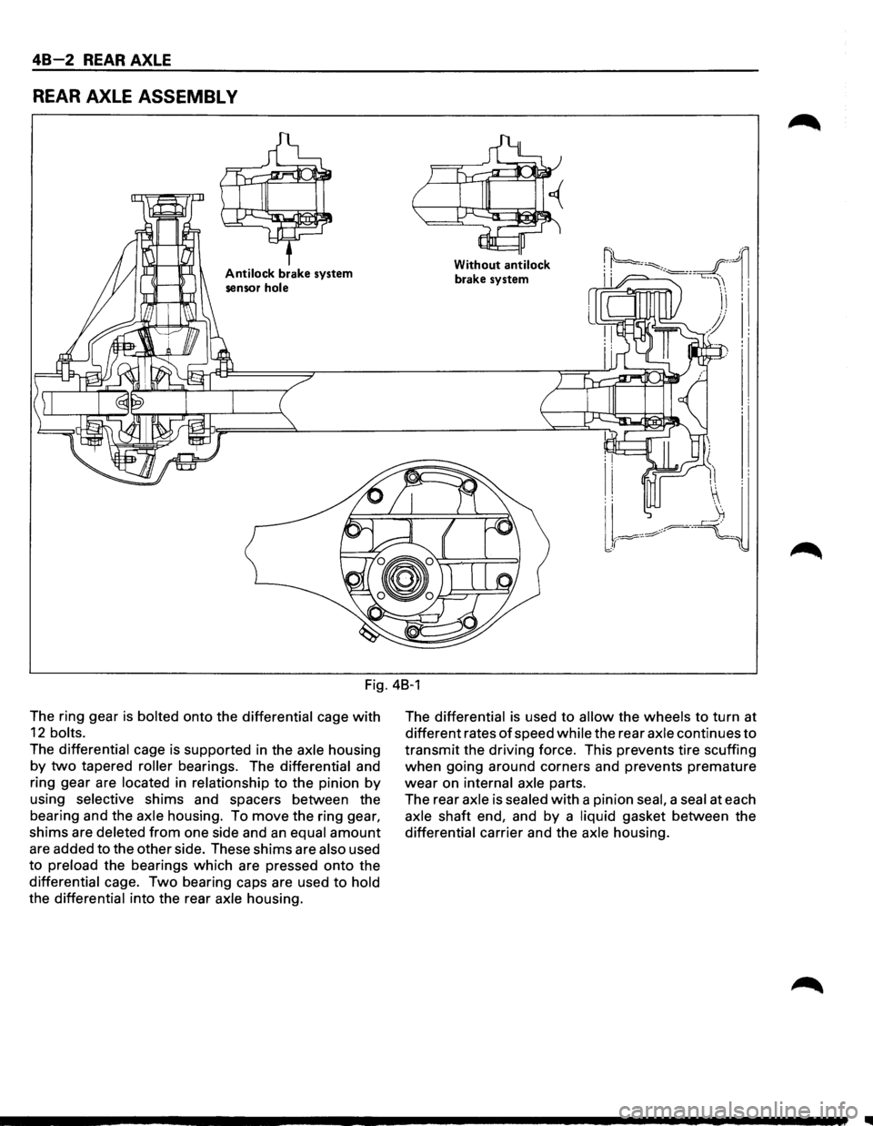
REAR AXLE ASSEMBL V
Antilock brake system
sensor
hole
Without antilock
brake system
Fig. 48-1
The ring gear
is bolted onto the differential cage with
12 bolts.
The differential cage is supported in the axle housing
by two tapered roller bearings. The differential and
ring gear are
located in relationship to the pinion by
using selective shims and spacers between the
bearing and the
axle housing. To move the ring gear,
shims are deleted from one side and an equal amount
are added to the other side. These shims are also used
to preload the bearings which are pressed onto the
differential cage. Two bearing caps are used to hold
the differential into the rear axle housing. The
differential is
used to allow the wheels to turn at
different rates
of speed while the rear axle continues to
transmit the driving force. This prevents tire scuffing
when going around corners and prevents premature
wear on internal axle parts.
The rear
axle is sealed with a pinion seal, a seal at each
axle shaft end, and by a liquid gasket between the
differential carrier and the axle housing.
II
Page 246 of 1928
48-4 REAR AXLE
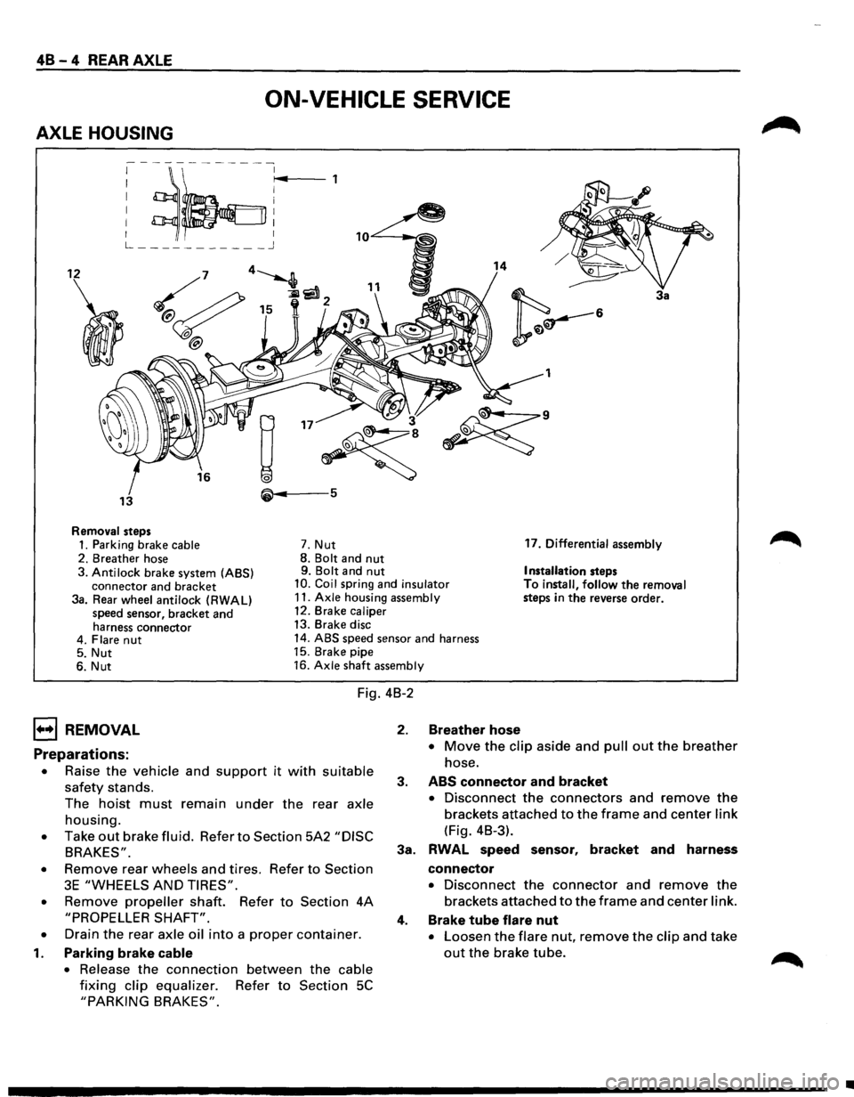
ON-VEHICLE SERVICE
AXLE HOUSING
; ~~:r~4 ,
L ___________ j
12 14
3a
1
• 3
~
~·
13 5
Removal steps
1. Parking brake cable 7. Nut 17.
Differential assembly
2. Breather hose 8.
Bolt and nut 9. Bolt and nut Installation steps
3. Anti lock brake system (ABS)
connector and bracket 10. Coil spring and insulator To install, follow the removal
steps in the reverse order.
3a. Rear wheel antilock (RWAL)
speed sensor, bracket and
harness connector 11.
Axle housing assembly
12. Brake caliper
13. Brake disc
4. Flare
nut 14. ABS speed sensor and harness
5. Nut 15.
Brake pipe
6. Nut 16.
Axle shaft assembly
Fig. 4B-2
1••1 REMOVAL
Preparations:
• Raise the vehicle and support it with suitable
safety stands.
The
hoist must remain under the rear axle
housing.
• Take out brake fluid. Refer to Section 5A2 "DISC
BRAKES".
•
Remove rear wheels and tires. Refer to Section
3E "WHEELS AND TIRES".
•
Remove propeller shaft. Refer to Section 4A
"PROPELLER SHAFT".
•
Drain the rear axle oil into a proper container.
1. Parking brake cable
•
Release the connection between the cable
fixing clip equalizer. Refer to Section 5C
"PARKING BRAKES".
2. Breather hose
• Move the clip aside and pull out the breather
hose.
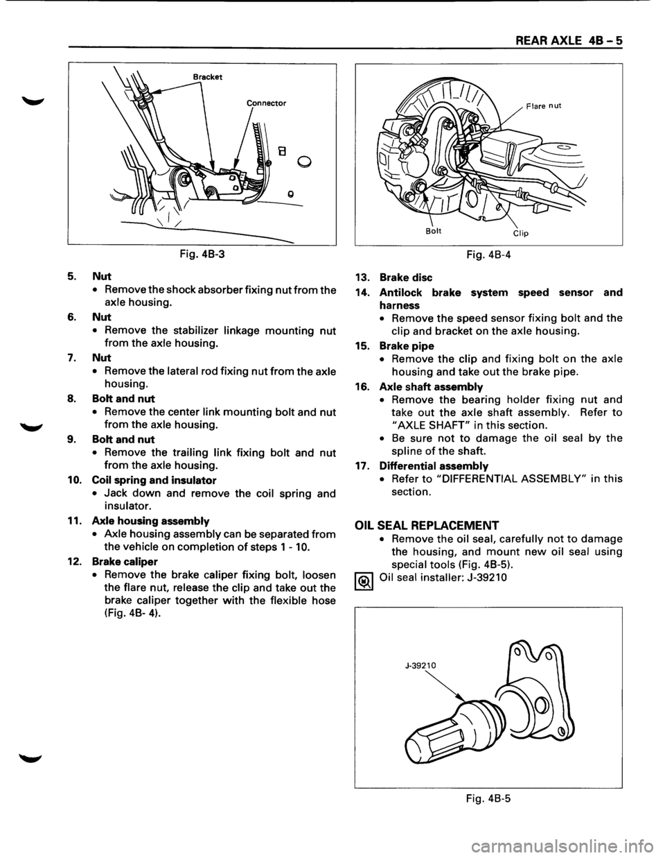
3. ABS connector and bracket
• Disconnect the connectors and remove the
brackets attached to the frame and center link
(Fig. 4B-3).
3a. RWAL speed sensor,
bracket and harness
connector
• Disconnect the connector and remove the
brackets attached to the frame and center link.
4. Brake tube flare nut
• Loosen the flare nut, remove the clip and take
out the brake tube.
•
Page 247 of 1928
5.
6.
7.
8.
........,
9.
10.
11.
12.
B 0
g
Fig. 48-3
Nut
• Remove the shock absorber fixing nut from the
axle housing.
Nut
• Remove the stabilizer linkage mounting nut
from the axle housing.
Nut
• Remove the lateral rod fixing nut from the axle
housing.
Bolt and nut
• Remove the center link mounting bolt and nut
from the axle housing .
Bolt and nut
• Remove the trailing link fixing bolt and nut
from the axle housing.
Coil spring and insulator
• Jack down and remove the coil spring and
insulator.
Axle housing assembly
• Axle
housing assembly can be separated from
the vehicle on completion of steps 1 -10.
Brake caliper
•
Remove the brake caliper fixing bolt, loosen
the
flare nut, release the clip and take out the
brake caliper
together with the flexible hose
(Fig. 48-
4).
REAR AXLE 48 - 5
Bolt Clip
Fig. 48-4
13. Brake disc
14.
Antilock brake system speed sensor and
harness
• Remove the speed sensor fixing bolt and the
clip and bracket on the axle housing.
15. Brake
pipe
• Remove the clip and fixing bolt on the axle
housing and take out the brake pipe.
16.
Axle shaft assembly
• Remove the bearing holder fixing nut and
take
out the axle shaft assembly. Refer to
"AXLE SHAFT" in this section.
• Be sure not to damage the oil seal by the
spline of the shaft.
17. Differential
assembly
• Refer to "DIFFERENTIAL ASSEMBLY" in this
section.
OIL SEAL REPLACEMENT
• Remove the oil seal, carefully not to damage
the housing, and mount new oil seal using
special tools (Fig. 48-5).
1®.1 Oil seal installer: J-39210
Fig. 48-5
Page 248 of 1928
48-6 REAR AXLE
1••1 INSTALLATION
17. Differential assembly
• Refer to "DIFFERENTIAL ASSEMBLY" in this
section.
16.
Axle shaft assembly
• Tighten the bearing holder mounting nut to the
specified torque.
~~~ Torque N·m (lb·ft) 74 (54)
• Be sure not to damage the oil seal by the spline
of the shaft.
15. Brake
pipe
14. Antilock brake system (ABS) speed sensor and
harness
• Refer to Section 5A4 "4-WHEEL ANTI-LOCK
BRAKE SYSTEM (ABS)".
13. Brake disc
12. Brake
caliper
• Refer to Section 5A2 "DISC BRAKES".
11.
Axle housing assembly
10. Coil spring and insulator
9. Bolt and nut
• For the procedures in Items 9-5, refer to Section
3D "REAR SUSPENSION".
8. Bolt and nut
7. Nut
6. Nut
5. Nut
4. Brake tube flare nut
• Refer to Section 5A2 "DISC BRAKES".
3a. Rear Wheel Antilock (RWAL) speed sensor,
bracket and harness connector
• Tighten the speed sensor bolt to the specified
torque.
1~1 Torque N-m (lb·ft) j 24 (18)
3. ABS connector and bracket
2. Breather hose
1. Parking brake cable
• Refer to Section 5C "PARKING BRAKES".
Page 249 of 1928
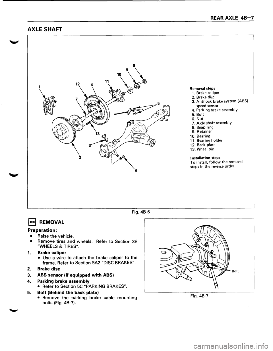
AXLE SHAFT
1
I
1••1 REMOVAL
Preparation:
• Raise the vehicle.
12 11
2
Fig. 4B-6
• Remove tires and wheels. Refer to Section 3E
"WHEELS & TIRES".
1. Brake caliper
• Use a wire to attach the brake caliper to the
frame. Refer to
Section 5A2 "DISC BRAKES".
2. Brake disc
3. ABS sensor (If equipped with ABS)
4. Parking brake assembly
• Refer to Section 5C "PARKING BRAKES".
5. Bolt (Behind the back plate)
• Remove the parking brake cable mounting
bolts (Fig. 4B-7).
REAR AXLE 48-7
Removal steps
1. Brake caliper
2. Brake disc
3. Antilock brake system (ABS)
speed sensor
4. Parking brake assembly
5. Bolt
6. Nut 7. Axle shaft assembly 8. Snap ring
9. Retainer
10. Bearing
11. Bearing holder
12. Back plate
13. Wheel pin
Installation steps To install, follow the removal
steps
in the reverse order.
Bolt
Fig. 4B-7
Page 251 of 1928
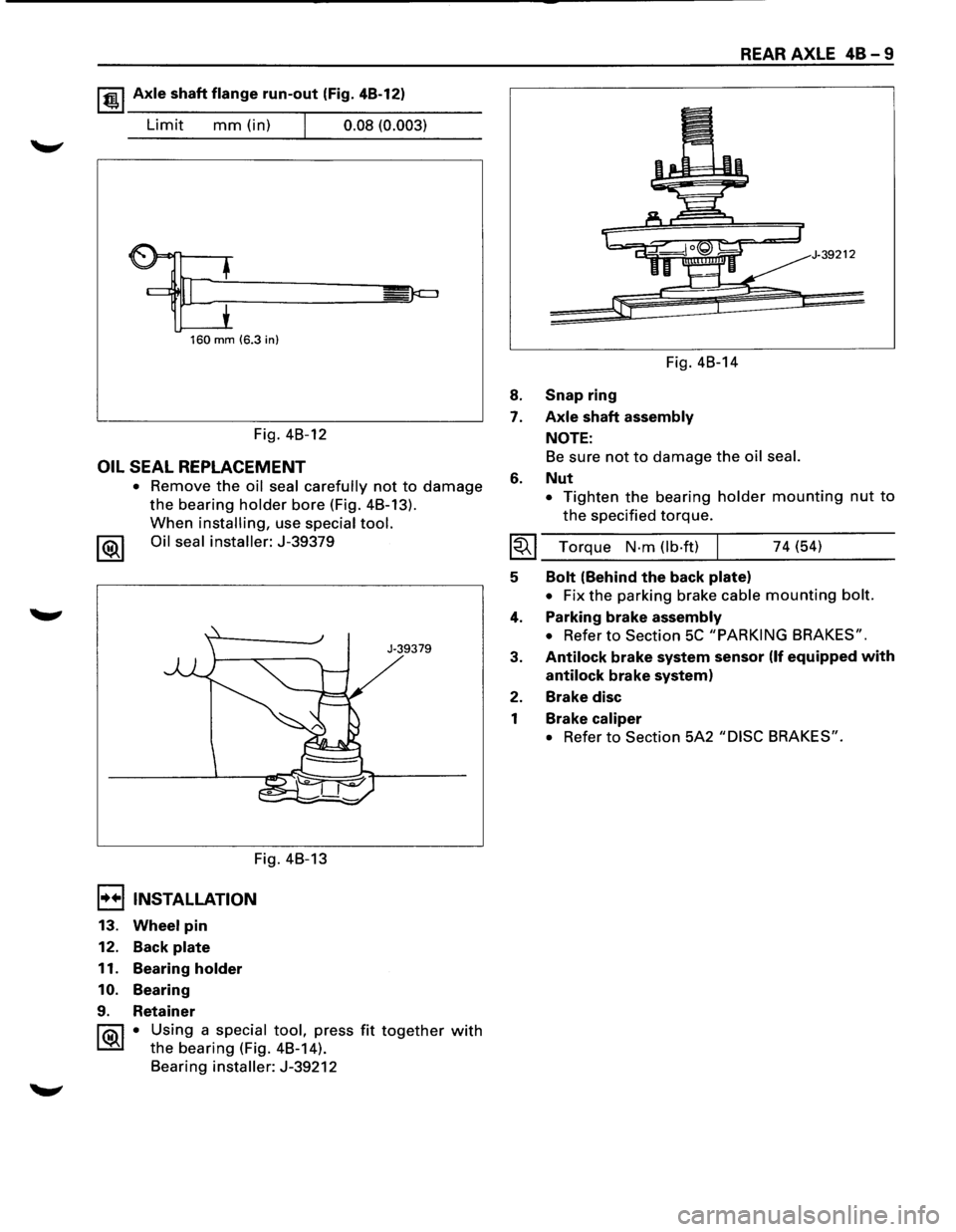
1 t!!.l Axle shaft flange run-out (Fig. 4B-12)
Limit mm (in) I 0.08 (0.003)
160 mm (6.3 in)
Fig. 4B-12
OIL SEAL REPLACEMENT
• Remove the oil seal carefully not to damage
the bearing holder bore (Fig. 4B-13).
When installing, use special tool.
1®1 Oil seal installer: J-39379
Fig. 4B-13
I••IINSTALLATION
13. Wheel pin
12. Back plate
11. Bearing holder
10. Bearing
9. Retainer
J-39379
1 ®I • Using a special tool, press fit together with
the bearing (Fig. 4B-14).
Bearing
installer: J-39212
8.
7.
6.
Fig. 4B-14
Snap ring
Axle shaft assembly
NOTE:
REAR AXLE 48-9
39212
Be sure not to damage the oil seal.
Nut
• Tighten the bearing holder mounting nut to
the specified torque.
I~I ___ T_o_rq_u_e __ N_·_m_(_lb_·f_t)~l _____ 7_4_(~5~4) ____ ___
5
4.
3.
2.
1
Bolt (Behind the back plate)
• Fix the parking brake cable mounting bolt.
Parking brake assembly
• Refer to Section 5C "PARKING BRAKES".
Antilock brake system sensor (If equipped with
antilock brake system)
Brake disc
Brake caliper
• Refer to Section 5A2 "DISC BRAKES".