wiring ISUZU TROOPER 1995 Repair Manual
[x] Cancel search | Manufacturer: ISUZU, Model Year: 1995, Model line: TROOPER, Model: ISUZU TROOPER 1995Pages: 1928
Page 790 of 1928
6E2-94 DRIVEABILITY AND EMISSIONS
3. If there is no revolution per minute (rpm) drop
on one or more cylinders, or excessive
variation is drop, check
for spark on the
suspected
cylinder(s) using a shop
oscilloscope or with J 26792 (ST-125) spark
tester
or equivalent. If no spark, refer to
ENGINE ELECTRICAL (SECTION 6D) for
intermittent operation of miss. If there is a
spark, remove spark
plug(s) in these cylinders
and check for:
-
Insulator Cracks.
- Wear.
-
Improper Gap.
- Burned
Electrodes.
-Heavy Deposits.
• CHECK: Spark plug wires by connecting
ohmmeter to ends of each wire in
question.
If meter reads over 30,000
ohms, replace wire(s).
FUEL SYSTEM
• CHECK: Fuel system -Plugged fuel filter, low
pressure. Use CHART A-7.
• CHECK: Contaminated fuel.
• CHECK: Injector drivers. Disconnect all injector
harness connectors. Connect
J 34730-2
Injector Test Light or equivalent 6 volts
test light between the harness terminal,
of each injector connector and note light
while
cranking. If test light fails to blink at
any connector, it is a faulty injector drive
circuit harness, connector
or terminal.
ENGINE MECHANICAL
• CHECK: Compression. Perform compression
check on
questionable cylinder(s) found
above.
If compression is low, repair as
necessary. Refer to ENGINE
MECHANICAL DIAGNOSIS (SECTION
6A).
• CHECK: Engine parts. Remove cam covers.
Check
for broken valve springs, worn
camshaft lobes and valve timing. Repair
as necessary. See ENGINE MECHANICAL
DIAGNOSIS (SECTION
6A).
ADDITIONAL CHECKS
• CHECK: For electromagnetic interference (EMI).
A missing condition can be caused by EMI
on the reference circuit. EMI can usually
be detected by monitoring engine speed
with a "Scan tool". A sudden increase in
rpm
with little change in actual engine
speed change, indicates
EMI is present. If
the problem exists, check routing of
secondary wires, check distributor
ground circuit.
• CHECK: Intake and exhaust manifold passage for
casting
flash.
ROUGH, UNSTABLE, OR INCORRECT IDLE, STALLING
Definition: Engine runs unevenly at idle. If severe, the
engine
or car may shake. Engine idle
speed may vary in rpm. Either condition
may be severe enough to stall engine.
PRELIMINARY CHECKS
• Perform the careful visual/physical checks as
described at start
of "Symptoms," Section "6E3-
B."
• CHECK:
• CHECK:
For vacuum leaks
Engine control module (ECM) grounds for
being clean, tight and proper routing.
See ECM wiring diagrams.
FUEL SYSTEM
• NOTICE: Monitoring L.T. Fuel Trim will help
identify the cause of the problem. If the
system is running
lean (LT. Fuel Trim
greater than 142), refer
to "Diagnostic
Aids"
on facing page of diagnostic trouble
code 44.
If the system is running rich (L.T. Fuel
Trim less than 118), refer to "Diagnostic
Aids" on facing page of diagnostic trouble
code 45.
• CHECK:
• CHECK:
• CHECK:
• CHECK:
• CHECK:
Incorrect minimum idle speed may be
caused
by foreign material accumulation
in the throttle bore coking, on the throttle
body or on the throttle shaft.
Clean injectors.
For
fuel in fuel pressure control valve
hose. If fuel is present, replace regulator
assembly.
Evaporative Emission Control System,
refer to "Evaporative Emission Control
System," Section "6E2-C3".
The Heated oxygen sensor should
respond quickly to different throttle
position, if it does not, check the heated
oxygen sensor
for silicon contaminations
from fuel, or use of improper RTV sealant.
The sensor will have a white, powdery
coating and will result in a high but false
signal voltage
(rich heated oxygen sensor
signal indication). The ECM will then
reduce the
amount of fuel delivered to the
engine, causing a severe
driveability
problem.
II
Page 795 of 1928
DRIVEABILITV AND EMISSIONS 6E2-99
SECTION C
COMPONENTS SYSTEMS
CAUTION
When fasteners are removed, always reinstall them at the same location from which they were removed. If a
fastener needs
to be replaced, use the correct part number fastener for that application. If the correct part number
fastener is not available, a fastener of equal size and strength (or stronger) may be used. Fasteners that are not
reused, and those requiring thread locking compound will be called out. The correct torque value must be used
when installing fasteners that require it. If the above conditions are not followed, parts or system damage could
result.
Section
"C" provides information on the following:
• General description of components and sub-systems.
• On-vehicle service.
• Part names and group numbers.
• Diagnostic charts. These include a functional check of the system as well as diagnosis of any problem found in
the functional check.
For locations
of components, wiring diagrams, and engine control module terminal and view, refer to the front of
"Engine Components/Wiring Diagrams/Diagnostic Charts", Section "A".
Refer to the following sections for the appropriate sub-system information:
• C1 Engine Control Module (ECM) and Sensors ................................. Page 6E2-1 00
•
C2 Fuel Metering System .................................................. Page 6E2-116
• C3 Evaporative Emission (EVAP) Control System ............................... Page 6E2-134
• C4 Electronic Ignition (EI) System/Ignition Control (IC) ........................... Page 6E2-138
• C5 Knock Sensor (KS) System .............................................. Page 6E2-146
• C7 Exhaust Gas Recirculation (EGR) System ................................... Page 6E2-151
• C8 Shift Indicator Light (M/T Only) ........................................... Page 6E2-157
• C1 0 Air Conditioning (A/C) Compressor Clutch Control System ..................... Page 6E2-161
• C13 Positive Crankcase Ventilation (PCV) ....................................... Page 6E2-164
DIAGNOSTIC CHARTS
The following diagnostic charts can be found at the end of some of the sections.
• Chart C-1A Park/neutral Position (PNP) Switch Diagnosis (Auto Transmission only) .... Page 6E2-108
• Chart C-1 D Manifold Absolute Pressure (MAP) Output Check ...................... Page 6E2-11 0
•
Chart C-1 E Power Steering Pressure (PSP) Switch Diagnosis ...................... Page 6E2-112
• Chart C-1 F Heated Oxygen Sensor (H02S) Heater Check ......................... Page 6E2-114
• Chart C-2A Injector Balance Test ............................................. Page 6E2-128
• Chart C-2C Idle Air Control (lAC) System Check ................................. Page 6E2-130
• Chart C-2D Induction Air Control System Check (DOHC Only) ...................... Page 6E2-132
• Chart C-3 Evaporate Emission Canister Purge Valve Check ....................... Page 6E2-136
• Chart C-4D-1 Electronic Ignition (EI) Misfire at Idle ................................ Page 6E2-142
• Chart C-4D-2 Electronic Ignition (EI) Misfire Under Load ............................ Page 6E2-144
• Chart C-5 Knock Sensor (KS) System Check .................................. Page 6E2-148
• Chart C-7A Exhaust Gas Recirculation (EGR) System Check ....................... Page 6E2-154
• Chart C-8 Manual Transmission (MIT) Shift Light Check ......................... Page 6E2-158
• Chart C-1 0 Air Conditioning (A/C) System Functional Check ....................... Page 6E2-162
Page 797 of 1928
will not light when connected to the circuit. In some
cases, even an ordinary shop voltmeter
will not give an
accurate reading because its resistance is
too low.
Therefore, a 10 megohms input impedance digital
voltmeter is required to assure accurate voltage
readings.
The Engine
Control Module (ECM) controls output
circuits such as the fuel injectors, idle air control valve,
air conditioning clutch relay, etc. by controlling the
ground circuit through transistors
or a device called a
"quad-driver".
INFORMATION SENSORS
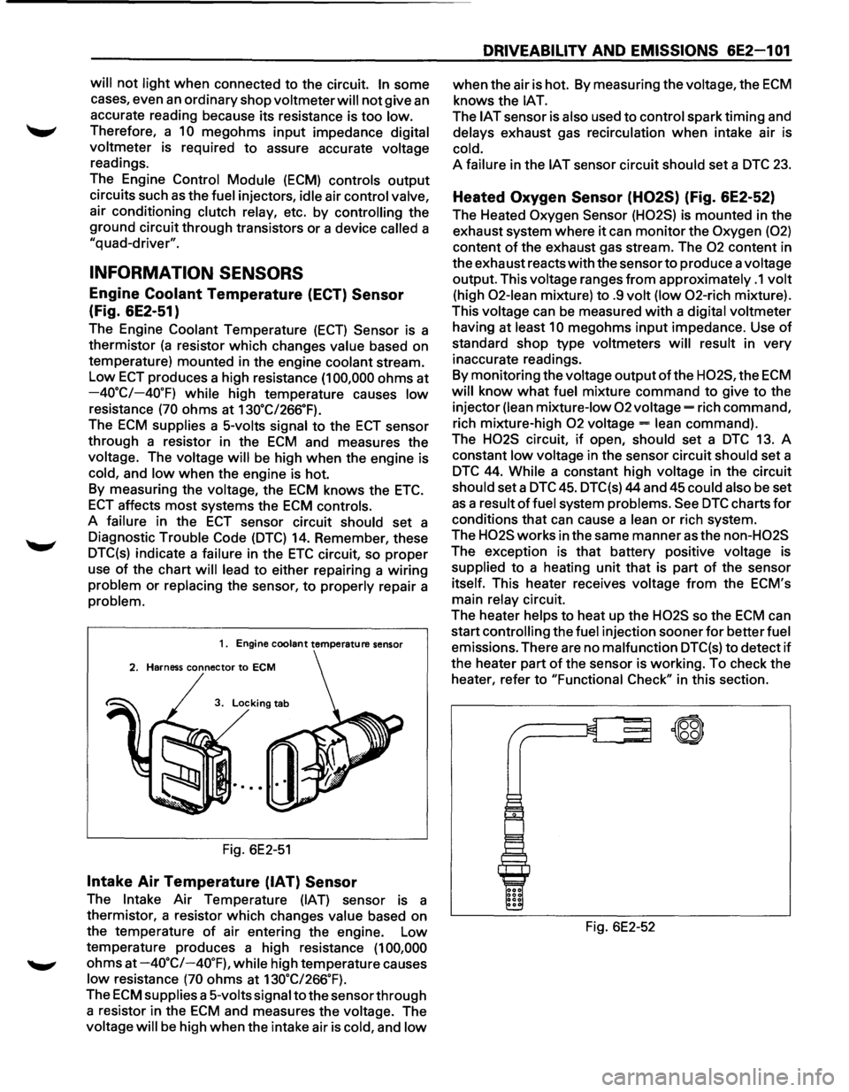
Engine Coolant Temperature (ECT) Sensor
(Fig. 6E2-51)
The Engine Coolant Temperature (ECT) Sensor is a
thermistor
(a resistor which changes value based on
temperature) mounted in the engine coolant stream.
Low ECT produces a high resistance (1 00,000 ohms at
-40.C/-40.F) while high temperature causes low
resistance (70 ohms at 130.C/266.F).
The ECM supplies a 5-volts signal to the ECT sensor
through a resistor in the
ECM and measures the
voltage. The voltage
will be high when the engine is
cold, and low when the engine is hot.
By measuring the voltage, the
ECM knows the ETC.
ECT affects most systems the ECM controls.
A failure in the
ECT sensor circuit should set a
Diagnostic Trouble Code
(DTC) 14. Remember, these
DTC(s) indicate a failure in the
ETC circuit, so proper
use
of the chart will lead to either repairing a wiring
problem or replacing the sensor, to properly repair a
problem.
1. Engine coolant temperature sensor
2. Harness connector to ECM
3. Locking tab
Fig. 6E2-51
Intake Air Temperature (IAT) Sensor
The Intake Air Temperature (IAT) sensor is a
thermistor, a resistor which changes
value based on
the temperature
of air entering the engine. Low
temperature produces a high resistance
(1 00,000
ohms at -4o·c/-40.F), while high temperature causes
low resistance (70 ohms at 130.C/266.F).
The ECM supplies a 5-volts signal to the sensor through
a resistor in the
ECM and measures the voltage. The
voltage
will be high when the intake air is cold, and low
DRIVEABILITV AND EMISSIONS 6E2-1 01
when the air is hot. By measuring the voltage, the ECM
knows the lAT.
The IAT sensor is also used to control spark timing and
delays exhaust gas recirculation when intake air is
cold.
A failure in the IAT sensor circuit should set a DTC 23.
Heated Oxygen Sensor (H02S) (Fig. 6E2-52)
The Heated Oxygen Sensor (H02S) is mounted in the
exhaust system where
it can monitor the Oxygen (02)
content of the exhaust gas stream. The 02 content in
the exhaust reacts
with the sensor to produce a voltage
output. This voltage ranges
from approximately .1 volt
(high 02-lean mixture) to .9 volt (low 02-rich mixture).
This voltage can
be measured with a digital voltmeter
having at
least 10 megohms input impedance. Use of
standard shop type voltmeters will result in very
inaccurate readings.
By monitoring the voltage
output ofthe H02S, the ECM
will know what fuel mixture command to give to the
injector
(lean mixture-low 02 voltage= rich command,
rich mixture-high
02 voltage= lean command).
The
H02S circuit, if open, should set a DTC 13. A
constant
low voltage in the sensor circuit should set a
DTC 44. While a constant high voltage in the circuit
should set a DTC 45. DTC(s) 44 and 45 could also be set
as a result of fuel system problems. See DTC charts for
conditions that can cause a lean or rich system.
The
H02S works in the same manner as the non-H02S
The exception is that battery positive voltage is
supplied to a heating unit that is part of the sensor
itself. This heater receives voltage
from the ECM's
main
relay circuit.
The heater
helps to heat up the H02S so the ECM can
start
controlling the fuel injection sooner for better fuel
emissions. There are no malfunction DTC(s) to detect if
the heater part of the sensor is working. To check the
heater, refer to "Functional
Check" in this section.
Fig. 6E2-52
~
\W
Page 798 of 1928
6E2-1 02 DRIVEABILITV AND EMISSIONS
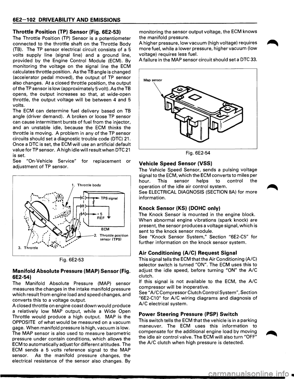
Throttle Position (TP) Sensor (Fig. 6E2-53)
The Throttle Position (TP) Sensor is a potentiometer
connected to the throttle shaft on the Throttle Body
(TB). The TP sensor electrical circuit consists of a 5
volts supply line (signal line) and a ground line,
provided by the Engine Control Module (ECM).
By
monitoring the voltage on the signal line the ECM
calculates throttle position. As the TB angle is changed
(accelerator pedal moved), the output
of TP sensor
also changes.
At a closed throttle position, the output
of the TP sensor is low (approximately 5volt). As the TB
opens, the output increases so that, at wide-open
throttle, the output voltage
will be between 4 and 5
volts.
The
ECM can determine fuel delivery based on TB
angle (driver demand). A broken or loose TP sensor
can cause intermittent bursts of fuel from the injector,
and
an unstable idle, because the ECM thinks the
throttle is moving. A problem in any
of the TP sensor
circuits should set a diagnostic trouble code
(DTC) 21.
Once a DTC is set, the ECM will use an artificial default
valueforTP sensor. A high idle will result when DTC 21
is set.
See
"On-Vehicle Service" for replacement or
adjustment
of TP sensor.
ECM
~--2. Throttle position
sensor (TPS)
Fig. 6E2-53
Manifold Absolute Pressure (MAP) Sensor (Fig.
6E2-54)
The Manifold Absolute Pressure (MAP) sensor
measures the changes in the intake manifold pressure
which result
from engine load and speed changes, and
converts this to a voltage output.
A closed throttle on engine coast
down would produce
a relatively
low MAP output, while a Wide Open
Throttle would produce a high output. MAP is the
OPPOSITE of what would be measured on a vacuum
gage. When manifold pressure is high, vacuum is low.
The
MAP sensor is also used to measure barometric
pressure under contain conditions, which
allows the
ECM to automatically adjust for different altitudes. The
ECM sends a 5 volts reference signal to the MAP
sensor. As the manifold pressure changes, the
electrical resistance
of the sensor also changes. By
monitoring the sensor output voltage, the ECM knows
the manifold pressure.
A higher pressure,
low vacuum (high voltage) requires
more fuel, while a lower pressure, higher vacuum (low
voltage) requires less
fuel.
A failure in the MAP sensor circuit should set a DTC 33.
Map sensor
Fig. 6E2-54
Vehicle Speed Sensor (VSS)
The Vehicle Speed Sensor, sends a pulsing voltage
signal to the
ECM, which the ECM converts to miles per
hour. This sensor helps to control the
operation
of the idle air control system.
See
ELECTRICAL DIAGNOSIS (SECTION 8A) for more
information.
Knock Sensor (KS) (DOHC only)
The Knock Sensor is mounted in the engine block.
When abnormal engine vibrations (spark knock) are
present, the sensor produces a voltage signal, which is
sent to the knock sensor module.
See
"Knock Sensor System," Section "6E2-C5" for
further information on the knock sensor system.
Air Conditioning (A/C) Request Signal
This signal tells the ECM that the Air Conditioning (A/C)
selector switch is turned
"ON". The ECM uses this to
adjust the idle speed, before turning
"ON" the A/C
clutch.
If this signal is not available to the ECM, the A/C
compressor will be inoperative.
See "A/C Compressor Clutch Control System", Section
"6E2-C1 0" for A/C wiring diagrams and diagnosis of
A/C electrical system.
Power Steering Pressure (PSP) Switch
This switch tells the ECM that the vehicle is in a parking
maneuver. The
ECM uses this information to
compensate
for the additional engine load by moving
the idle air control valve. The
ECM will also turn "OFF"
the A/C clutch when high pressure is detected.
•
Page 802 of 1928
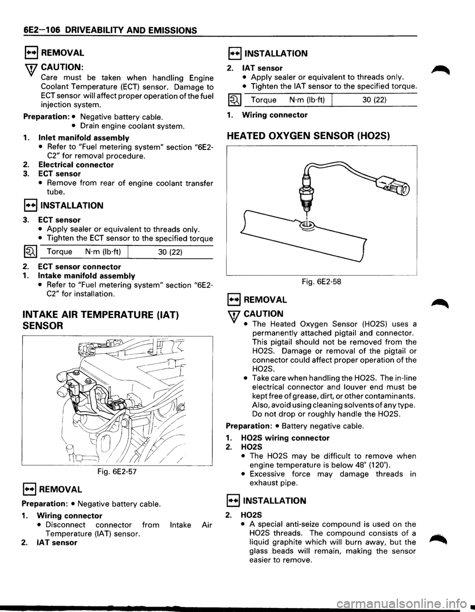
6E2-1 06 DRIVEABILITV AND EMISSIONS
1••1 REMOVAL
\f7 CAUTION:
Y/ Care must be taken when handling Engine
Coolant Temperature (ECT) sensor. Damage to
ECT sensor will affect proper operation of the fuel
injection system.
Preparation: • Negative battery cable.
•
Drain engine coolant system.
1. Inlet manifold assembly
• Refer to "Fuel metering system" section "6E2-
C2"
for removal procedure.
2. Electrical connector
3. ECT sensor
• Remove from rear of engine coolant transfer
tube.
I••IINSTALLATION
3. ECT sensor
• Apply sealer or equivalent to threads only.
•
Tighten the ECT sensor to the specified torque
~~~ Torque N·m (lb·ft) I 30 (22)
2. ECT sensor connector
1. Intake manifold assembly
• Refer to "Fuel metering system" section "6E2-
C2" for installation.
INTAKE AIR TEMPERATURE (IAT)
SENSOR
Fig. 6E2-57
1••1 REMOVAL
Preparation: • Negative battery cable.
1. Wiring connector
• Disconnect connector from Intake Air
Temperature (IAT) sensor.
2. IAT sensor
I••IINSTALLATION
2. IAT sensor
• Apply sealer or equivalent to threads only.
•
Tighten the IAT sensor to the specified torque.
~~~ Torque N·m (lb·ft) 30 (22)
1. Wiring
connector
HEATED OXYGEN SENSOR (H02S)
Fig. 6E2-58
1••1 REMOVAL
'fCAUTION
• The Heated Oxygen Sensor (H02S) uses a
permanently attached pigtail and connector.
This
pigtail should not be removed from the
H02S. Damage or removal of the pigtail or
connector
could affect proper operation of the
H02S.
•
Take care when handling the H02S. The in-line
electrical
connector and louver end must be
kept free
of grease, dirt, or other contaminants.
Also, avoid using cleaning solvents of any type.
Do not drop or roughly handle the H02S.
Preparation: • Battery negative cable.
1. H02S wiring connector
2. H02S
• The H02S may be difficult to remove when
engine temperature is
below 48• (120.).
•
Excessive force may damage threads in
exhaust pipe.
I••IINSTALLATION
2. H02S
• A special anti-seize compound is used on the
H02S threads. The compound consists of a
liquid graphite which will burn away, but the
glass beads will remain, making the sensor
easier
to remove.
•
Page 803 of 1928
New or service sensors will already have the
compound
applied to the threads. If a sensor is
removed
from an engine and iffor any reason it
is to be reinstalled, the threads must have anti
seize compound
applied before reinstallation.
•
Apply anti-seize compound or equivalent to
threads of oxygen sensor if necessary.
• Tighten the oxygen sensor to the specified
torque.
1~1 Torque N·m (lb·ft) 55 (40)
1. H02S wiring connector
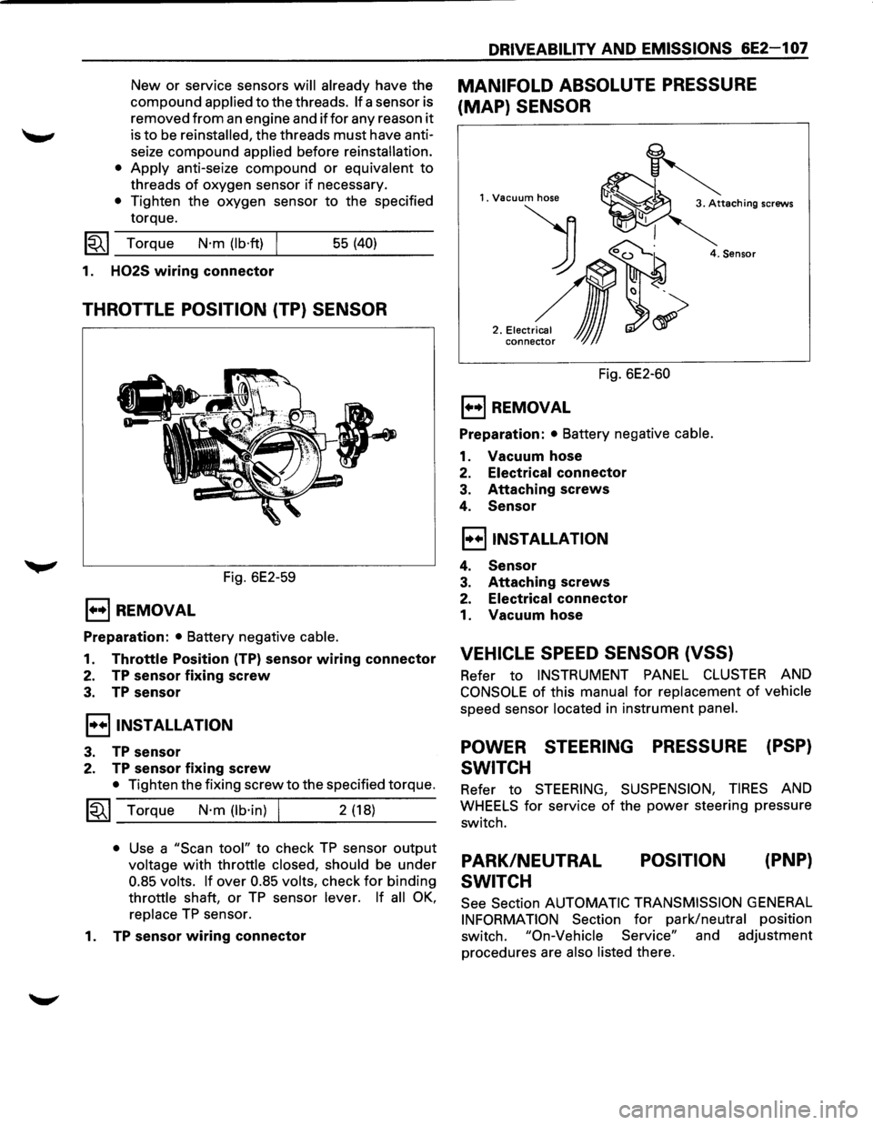
THROTTLE POSITION (TP) SENSOR
Fig. 6E2-59
E) REMOVAL
Preparation: • Battery negative cable.
1. Throttle Position (TP) sensor wiring connector
2. TP sensor fixing screw
3. TP sensor
I••IINSTALLATION
3. TP sensor
2. TP sensor fixing screw
• Tighten the fixing screw to the specified torque.
~~~ Torque N·m (lb·in) I 2 (18)
• Use a "Scan tool" to check TP sensor output
voltage with throttle closed, should be under
0.85 volts. If over 0.85 volts, check for binding
throttle shaft, or TP sensor lever. If all OK,
replace TP sensor.
1.
TP sensor wiring connector
DRIVEABILITY AND EMISSIONS 6E2-1 07
MANIFOLD ABSOLUTE PRESSURE
(MAP) SENSOR
1. Vacuum hose
) 0~
2 .• ,.~,,~,~
conne~ JJJ
4. Sensor
Fig. 6E2-60
E) REMOVAL
Preparation: • Battery negative cable.
1. Vacuum hose
2. Electrical connector
3. Attaching screws
4. Sensor
I••IINSTALLATION
4. Sensor
3. Attaching screws
2. Electrical connector
1. Vacuum hose
VEHICLE SPEED SENSOR (VSS)
Refer to INSTRUMENT PANEL CLUSTER AND
CONSOLE of this manual for replacement of vehicle
speed sensor located in instrument panel.
POWER STEERING PRESSURE (PSP)
SWITCH
Refer to STEERING, SUSPENSION, TIRES AND
WHEELS for service of the power steering pressure
switch.
PARK/NEUTRAL
SWITCH POSITION
(PNP}
See
Section AUTOMATIC TRANSMISSION GENERAL
INFORMATION Section for park/neutral position
switch.
"On-Vehicle Service" and adjustment
procedures are
also listed there.
Page 804 of 1928
6E2-1 08 DRIVEABILITV AND EMISSIONS
CHART C-1A
PARK/NEUTRAL POSITION (PNP} SWITCH DIAGNOSIS
(AUTO TRANSMISSION ONL
V}
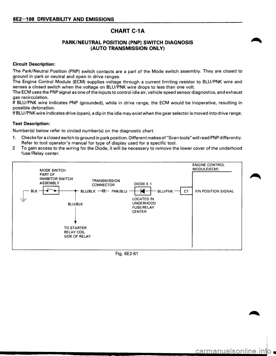
Circuit Description:
The
Park/Neutral Position (PNP) switch contacts are a part of the Mode switch assembly. They are closed to
ground in park or neutral and open in drive ranges.
The Engine
Control Module (ECM) supplies voltage through a current limiting resistor to BLU/PNK wire and
senses a
closed switch when the voltage on BLU/PNK wire drops to less than one volt.
The ECM uses the PNP signal as one ofthe inputs to control idle air, vehicle speed sensor diagnostics, and exhaust
gas recirculation.
If BLU/PNK wire indicates PNP (grounded), while in drive range, the ECM would be inoperative, resulting in
possible detonation.
If BLU/PNK wire indicates drive (open), a dip in the idle may exist when the gear selector is moved into drive range.
Test Description:
Number(s)
below refer to circled number(s) on the diagnostic chart.
1. Checks for a closed switch to ground in park position. Different makes of "Scan tools" will read PNP differently.
Refer to tool operator's manual for type of display used for a specific tool.
2 To gain access to the wiring for the Diode, it will be necessary to remove the lower cover of the underhood
fuse/Relay center.
MODE SWITCH PART OF
INHIBITOR SWITCH TRANSMISSION ASSEMBLY CONNECTOR
_[ BLK +~•+1-------rt--BLU/BLK -{~ PNK/BLU
-BLU/BLK
l
TO STARTER
RELAY COIL
SIDE OF RELAY
DIODE E-1
ENGINE CONTROL MODULE(ECM)
~ BLU/PNK ~ P/N POSITION SIGNAL
LOCATED IN
UNDERHOOD
FUSE/RELAY
CENTER
Fig. 6E2-61
Ill
Page 817 of 1928
Throttle Position (TP) Sensor
The Throttle Position (TP) Sensor is mounted on the
side
of the throttle body opposite the throttle lever
assembly.
Its function is to sense the current throttle
body position and relay that information to the ECM.
Knowledge ofTP is needed by the ECM to generate the
proper injector pulse width.
If the TP sensor senses a
Wide
Open Throttle, a voltage signal indicating this
condition is transmitted to the
ECM. The ECM will
widen the injector pulse, or increase the repetition rate,
permitting increased fuel
flow to each for the six fuel
injectors located in the fuel fail. As the throttle shaft
rotates in response to
movement of the accelerator
pedal (opening
or closing of the throttle body), the
throttle shaft transmits throttle
movement to the TP
sensor. A potentiometer (variable resistor) within the
TP sensor assembly creates a voltage that varies in
response to
TP. By applying a reference voltage (+5
VDC) to the TP sensor input, a varying voltage
(reflecting
TP) is available at the TP sensor output. The
voltage
output from the TP sensor is sent to the ECM
for use in determining current TP.
For further information ofTP sensor, refer to "ECM and
Sensors", Section
"6E2-C1 ". The TP sensor is an auto
zeroing type and cannot
be adjusted.
DRIVEABILITY AND EMISSIONS 6E2-121
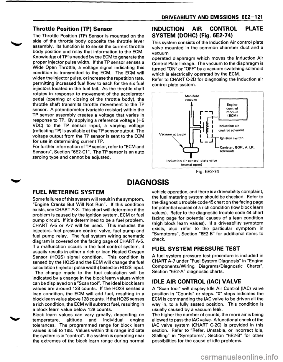
INDUCTION AIR CONTROL PLATE
SYSTEM (DOHC) (Fig. 6E2-74)
This system consists of the Induction Air control plate
valve mounted in the common chamber
duct and a
vacuum operated diaphragm
which moves the Induction Air
Control Plate linkage. The vacuum to the diaphragm is
turned
"ON" or "OFF" by a vacuum switching solenoid
which is electrically operated by the
ECM.
Refer to CHART C-20 for diagnosing the Induction air
control plate system.
Manifold vaccum
1
Vacuum actuator
Induction air control plate valve
(noma! open)
Fig. 6E2-74
Engine control module (ECM)
Ignition switch
Canister, EGR, A.I.R. solenoids
DIAGNOSIS
FUEL METERING SYSTEM
Some failures of this system will result in the symptom,
"Engine Cranks But Will Not Run". If this condition
exists, see CHART A-3. This chart will determine
if the
problem is caused by the ignition system,
ECM or fuel
pump circuit.
If it's determined to be a fuel problem.
CHART A-5
or A-7 will be used. This includes the
injectors, fuel pressure control valve, fuel
pump and
fuel pump relay. The fuel system
wiring schematic
diagram is covered on the facing page
of CHART A-5.
If a malfunction occurs in the fuel control system, it
usually results in either a rich or lean Heated Oxygen
Sensor (H02S) signal condition. This condition is
sensed by the
H02S and the ECM will change the fuel
calculation (injector pulse width) based on
H02S input.
The change made to the fuel calculation will be
indicated
by a change in the block learn values which
can be displayed on a
"Scan tool". The ideal block learn
values are around 128 counts.
If the H02S senses a
lean condition, the
ECM will add fuel, resulting in a
block learn value above 128 counts.
If the H02S senses
a rich condition, the
ECM will subtract fuel, resulting in
a block learn value below 128 counts.
Block learn values can vary greatly, depending on
temperature, altitude and individual engine
tolerances. The programmed range for block learn
values is
58 to 198. Values within this range indicate
the system is in
"control". If a system is operating near
the extremes
of the block learn range during normal vehicle
operation, and there is a driveability complaint,
the fuel metering system should be checked. Refer to
the diagnostic trouble code
45 chart on the facing page
for potential causes of a rich condition (low block learn
values). Refer to the diagnostic trouble code 44 chart
facing page
for potential causes of a lean condition
(high block learn values).
If a driveability symptom
exists, also refer to the particular symptom in
"Symptoms", Section "6E2-B" for additional items to
check.
FUEL SYSTEM PRESSURE TEST
A fuel system pressure test procedure is included in
CHART A-7 under
"Fuel System Diagnosis" in "Engine
Components/Wiring Diagrams/Diagnostic
Charts",
Section "6E2-A" diagnostic charts.
IDLE AIR CONTROL (lAC) VALVE
A "Scan tool" will display Idle Air Control (lAC) valve
position in
"Counts" or steps. "0" steps indicates the
ECM is commanding the lAC valve to be driven all the
way in, to a fully seated position. This condition is
usually caused by a vacuum leak.
The higher the number
of counts, the more air is being
allowed to pass the
lAC valve. A functional check of the
lAC valve system (CHART C-2C) is provided in this
section. Refer to
"Refer, Unstable, or Incorrect Idle,
Stalling"
in "Symptoms", Section "6E2-B" for other
possibilities
for the cause of idle problems.
Page 857 of 1928
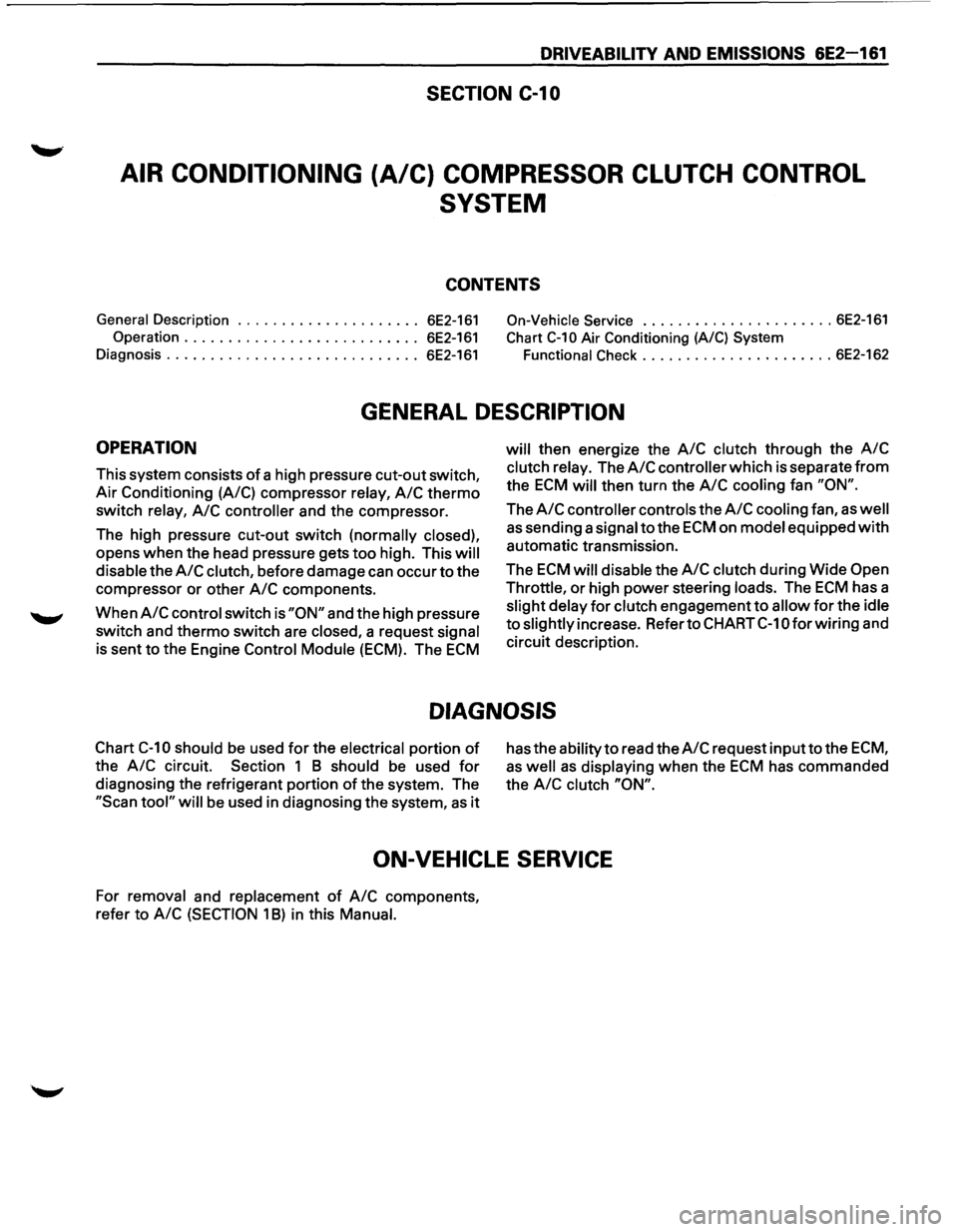
DRIVEABILITV AND EMISSIONS 6E2-161
SECTION C-1 0
AIR CONDITIONING (A/C) COMPRESSOR CLUTCH CONTROL
SYSTEM
CONTENTS
General Description ..................... 6E2-161 On-Vehicle Service ...................... 6E2-161
Operation ........................... 6E2-161 Chart C-10 Air Conditioning (A/C) System
Diagnosis ............................. 6E2-161 Functional Check ...................... 6E2-162
GENERAL DESCRIPTION
OPERATION
This system consists of a high pressure cut-out switch,
Air Conditioning (A/C) compressor
relay, A/C thermo
switch relay, A/C controller and the compressor.
The high pressure cut-out switch
(normally closed),
opens when the head pressure gets too high. This will
disable
the A/C clutch, before damage can occur to the
compressor or other
A/C components.
When
A/C control switch is "ON" and the high pressure
switch and thermo switch are
closed, a request signal
is sent to the Engine Control Module (ECM). The ECM
will then energize the A/C clutch through the A/C
clutch relay. The A/C controller which is separate from
the ECM will then turn the A/C cooling fan "ON".
The A/C controller controls the A/C cooling fan, as well
as sending a signal to the ECM on model equipped with
automatic transmission.
The
ECM will disable the A/C clutch during Wide Open
Throttle,
or high power steering loads. The ECM has a
slight delay for clutch engagement to allow for the idle
to slightly increase. Refer to CHART C-1 0 for wiring and
circuit description.
DIAGNOSIS
Chart C-10 should be used for the electrical portion of
the A/C circuit. Section 1 B should be used for
diagnosing the refrigerant portion of the system. The
"Scan tool" will be used in diagnosing the system, as it
has the ability to read the A/C request inputto the ECM,
as well as displaying when the ECM has commanded
the
A/C clutch "ON".
ON-VEHICLE SERVICE
For removal and replacement of A/C components,
refer to
A/C (SECTION 1 B) in this Manual.
Page 873 of 1928
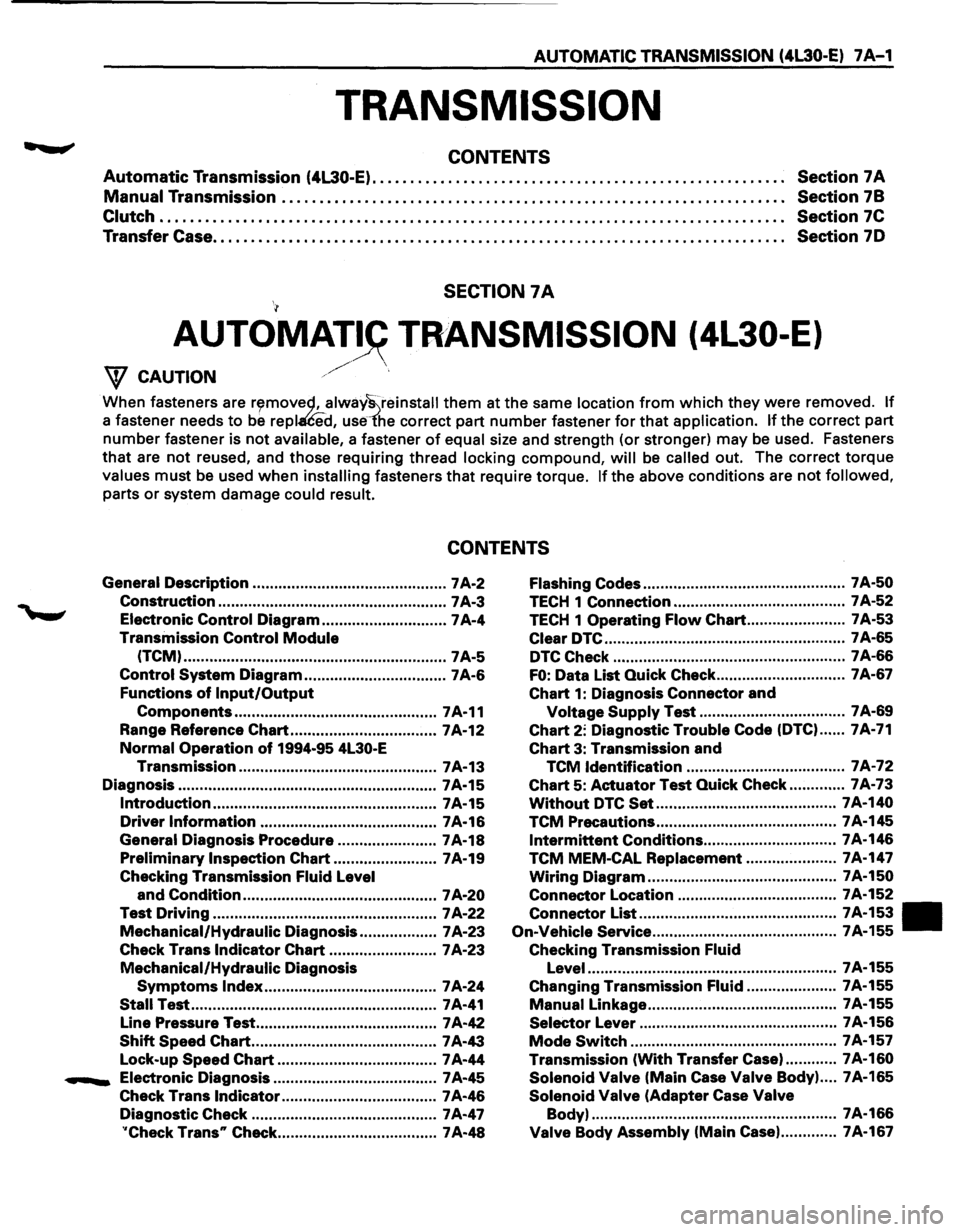
AUTOMATIC TRANSMISSION (4l30-E) 7 A-1
TRANSMISSION
CONTENTS
Automatic Transmission (4L30-E). . . . . . . . . . . . . . . . . . . . . . . . . . . . . . . . . . . . . . . . . . . . . . . . . . . . . . . Section 7 A
Manual Transmission . .
. . . . . . . . . . . . . . . . . . . . . . . . . . . . . . . . . . . . . . . . . . . . . . . . . . . . . . . . . . . . . . . . . Section
78
Clutch . . . . . . . . . . . . . . . . . . . . . . . . . . . . . . . . . . . . . . . . . . . . . . . . . . . . . . . . . . . . . . . . . . . . . . . . . . . . . . . . . . . Section 7C
Transfer Case. . . . . . . . . . . . . . . . . . . . . . . . . . . . . . . . . . . . . . . . . . . . . . . . . . . . . . . . . . . . . . . . . . . . . . . . . . . . Section 70
SECTION 7A
AUTOMAT~ TRANSMISSION (4L30-E)
/' W CAUTION ./
When fasteners are r~movec;l, alway~reinstall them at the same location from which they were removed. If
a fastener needs to be repl£ed, use1'he correct part number fastener for that application. If the correct part
number fastener is not available, a fastener of equal size and strength (or stronger) may be used. Fasteners
that are not reused, and those requiring thread locking compound, will be called out. The correct torque
values must be used when installing fasteners that require torque. If the above conditions are not followed,
parts or system damage could result.
CONTENTS
General Description ............................................. 7 A-2 Flashing Codes ............................................... 7 A-50
Construction ..................................................... 7 A-3 TECH 1 Connection ........................................ 7 A-52
Electronic Control Diagram ............................. 7A-4 TECH 1 Operating Flow Chart ....................... 7 A-53
Transmission
Control Module Clear DTC ........................................................ 7 A-65
(TCM) ............................................................. 7A-5 DTC Check ...................................................... 7 A-66
Control System Diagram ................................. 7 A-6 FO: Data List Quick Check .............................. 7A-67
Functions
of Input/Output Chart 1: Diagnosis Connector and
Components ............................................... 7A-11 Voltage Supply Test .................................. 7A-69
Range Reference
Chart .................................. 7A-12 Chart 2: Diagnostic Trouble Code (DTC) ...... 7A-71
Normal Operation of 1994-95 4L30-E Chart 3: Transmission and
Transmission .............................................. 7 A-13
TCM Identification ..................................... 7 A-72
Diagnosis ............................................................ 7A-15
Chart 5: Actuator Test Quick Check ............. 7A-73
Introduction .................................................... 7A-15 Without DTC Set .......................................... 7 A-140
Driver Information ......................................... 7 A-16 TCM Precautions .......................................... 7A-145
General Diagnosis Procedure ....................... 7A-18 Intermittent Conditions ............................... 7A-146
Preliminary Inspection Chart ........................ 7 A-19 TCM MEM-CAL Replacement ..................... 7A-147
Checking Transmission Fluid Level Wiring Diagram ............................................ 7A-150
and
Condition ............................................. 7 A-20 Connector Location
..................................... 7A-152
Test Driving .................................................... 7 A-22
Mechanical/Hydraulic Diagnosis .................. 7 A-23
Connector List .............................................. 7A-153 •
On-Vehicle
Service ........................................... 7A-155
Check Trans Indicator Chart ......................... 7 A-23 Checking Transmission Fluid
Mechanical/Hydraulic
Diagnosis Level .......................................................... 7A-155
Symptoms Index ........................................ 7A-24 Changing Transmission Fluid ..................... 7A-155
Stall Test ......................................................... 7 A-41 Manual Linkage ............................................ 7A-155
Line Pressure Test .......................................... 7 A-42
Selector Lever .............................................. 7 A-156
Shift Speed Chart ........................................... 7 A-43 Mode Switch ................................................ 7A-157
Lock-up
Speed Chart ..................................... 7 A-44 Transmission
(With Transfer Case). ........... 7A-160
....._ Electronic Diagnosis ...................................... 7 A-45 Solenoid Valve (Main Case Valve Body) .... 7A-165
Check Trans Indicator .................................... 7 A-46 Solenoid Valve (Adapter Case Valve
Diagnostic Check ........................................... 7 A-47 Body)
......................................................... 7A-166
''Check Trans" Check ..................................... 7 A-48 Valve Body Assembly (Main Case) ............. 7A-167