oil ISUZU TROOPER 1995 Workshop Manual
[x] Cancel search | Manufacturer: ISUZU, Model Year: 1995, Model line: TROOPER, Model: ISUZU TROOPER 1995Pages: 1928
Page 1293 of 1928
![ISUZU TROOPER 1995 Workshop Manual REAR DEFOGGER SWITCH
(1!] INSPECTION
I~~ Check to see if there is any continuity between
the terminals
of the defogger switch. (Fig. 8-127)
Replace the switch, when the result
of inspecti](/img/61/57183/w960_57183-1292.png "ISUZU TROOPER 1995 Workshop Manual REAR DEFOGGER SWITCH
(1!] INSPECTION
I~~ Check to see if there is any continuity between
the terminals
of the defogger switch. (Fig. 8-127)
Replace the switch, when the result
of inspecti")
REAR DEFOGGER SWITCH
(1!] INSPECTION
I~~ Check to see if there is any continuity between
the terminals
of the defogger switch. (Fig. 8-127)
Replace the switch, when the result
of inspection
is found abnormal.
a [~~·~] ]]
r ~)
~0. s 1
4
ON o-r--0---
OFF o-~
Fig. 8-127
B REMOVAL (FIG. 8-128)
5. Rear defogger switch
Fig. 8-128
[ill
5 2 1 s
-o
~
4. Instrument panel
.cluster assembly
CHASSIS ELECTRICAL 8-103
Preparation: Disconnect the battery ground cable.
1.
Front console assembly
2. Lower cluster assembly
3. Instrument panel driver lower cover
4. Instrument panel cluster assembly
• Refer to FOG LIGHT SWITCH removal steps
in
this section.
5.
Rear defogger switch
• To remove the switch, pushing the lock from
the back side of the cluster assembly.
E) INSTALLATION
To install, follow the removal steps in the reverse
order, noting
the following point.
1. Push in the switch with your fingers until it locks
securely.
REAR DEFOGGER HEAT WIRES
w CAUTION:
• Heat wires are printed on the inner side of
the rear glass.
To clean, use a
soft cloth and wipe horizon
tally along the wires.
• Never use glass cleaner or equivalent.
~ INSPECTION
It~ I Measure the voltage of heat wire.
Repair the heat wire
when the result of inspection
is found abnormal.
'f CAUTION:
• When measuring voltage, wind a piece of
tin foil around the tip of the negative probe
and press
the foil against the wire with your
finger (Fig. 8-129).
1. Turn the starter switch on.
2. Turn the rear defogger switch on.
3. Measure the voltage between the three points
on
the heat wire and the(-) terminal with a voltmeter.
4. Check that the voltage becomes smaller from ®
to @to© (Fig. 8-130).
5. If there is a place where the voltage suddenly
changes
to OV, there is a OPEN CIRCUIT between
there and the
prior point.
Page 1314 of 1928
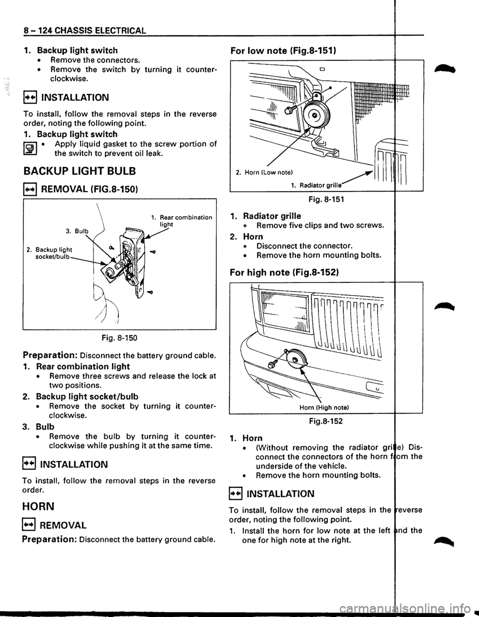
8-124 CHASSIS ELECTRICAL
1. Backup light switch For low note (Fig.S-151)
• Remove the connectors.
• Remove the switch by turning it counter
clockwise.
B INSTALLATION
To install, follow the removal steps in the reverse
order,
noting the following point.
1.
Backup light switch
li:i1 • Apply liquid gasket to the screw portion of
~ the switch to prevent oil leak.
BACKUP LIGHT BULB
B REMOVAL (FIG.S-150)
2. Backup light
socket/bulb
i ''V
f
~h /) i/
Fig. 8-150
Preparation: Disconnect the battery ground cable.
1. Rear combination light
• Remove three screws and release the lock at
two positions.
2.
Backup light socket/bulb
• Remove the socket by turning it counter
clockwise.
3. Bulb
• Remove the bulb by turning it counter
clockwise
while pushing it at the same time.
B INSTALLATION
To install, follow the removal steps in the reverse
order.
HORN
B REMOVAL
Preparation: Disconnect the battery ground cable.
Fig. 8-151
1.
Radiator grille
o Remove five clips and two screws.
2. Horn
o Disconnect the connector.
• Remove the horn mounting bolts.
For high note (Fig.S-152)
Horn (High note)
Fig.8-152
1. Horn
• {Without removing the radiator gri e) Dis
connect the connectors of the horn f om the
underside
of the vehicle.
•
Remove the horn mounting bolts.
8 INSTALLATION
To install, follow the removal steps in the everse
order, noting the
following point.
1. Install the horn for low note at the left nd the
one
for high note at the right. ~
Page 1382 of 1928
8-192 CHASSIS ELECTRICAL
TRANSMISSION CONTROL MODULE (TCM)
GENERAL DESCRIPTION
The circuit consists of the starter switch, TCM, mode switch, brake switch, speed sensor, kick down switch,
Power and
Winter switches, Throttle Position (TP) sensor, Engine Control Module (ECM), barometer sensor,
adapter case, main case,
warning light (CHECK TRANS, NT OIL TEMP) and indicator light (WINTER DRIVE,
POWER DRIVE).
The TCM, based on the predetermined shifting characteristics and lockup operating valve, provides the
optimum shifting control to the varying vehicle running condition. The following input signals are sent to the
TCM: select lever position from the mode switch, running mode from the POWER & WINTER switches,
throttle opening from the TP sensor, vehicle speed from the vehicle speed sensor and engine speed from the
ECM are sent to the TCM. After receiving these signals, the TCM determines the vehicle running condition,
and
it sends output signals to each solenoid to control shifting.
When the
TCC solenoid is engaged, the lockup mechanism operates.
The shift
solenoid 2.3 and 1.2/3.4 selects the shift gear position.
The force
motor controls the line pressure to improve shifting.
Also, when the TCM detects an abnormal signal from the transmission or sensor, it will cause the "CHECK
TRANS"
light on the warning box to flash in order to inform the driver of the malfunction.
Refer to section 7 A "AUTOMATIC TRANSMISSION" for details.
•
Page 1436 of 1928
8-246 CHASSIS ELECTRICAL
AUDIO, AUTO ANTENNA, CIGARETTE LIGHTER AND DIGITAL CLOCK
GENERAL DESCRIPTION
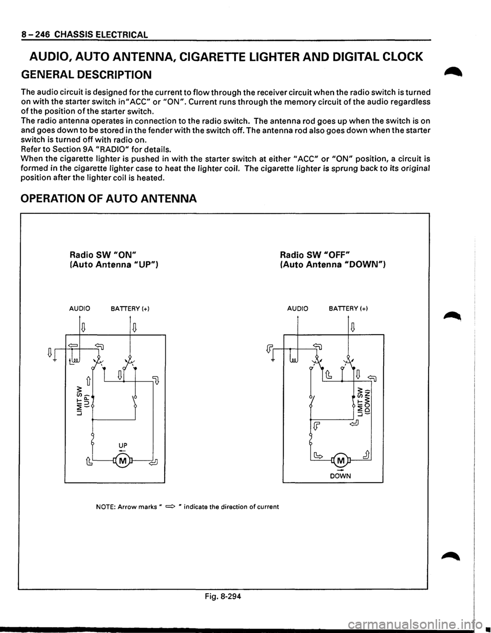
The audio circuit is designed for the current to flow through the receiver circuit when the radio switch is turned
on
with the starter switch in" ACC" or "ON". Current runs through the memory circuit of the audio regardless
of the position of the starter switch.
The radio antenna operates in connection
to the radio switch. The antenna rod goes up when the switch is on
and goes
down to be stored in the fender with the switch off. The antenna rod also goes down when the starter
switch is turned
off with radio on.
Refer
to Section 9A "RADIO" for details.
When the cigarette lighter is pushed in
with the starter switch at either "ACC" or "ON" position, a circuit is
formed in the cigarette lighter case
to heat the lighter coil. The cigarette lighter is sprung back to its original
position after the lighter coil
is heated.
OPERATION OF AUTO ANTENNA
Radio SW "ON"
(Auto Antenna "UP")
AUDIO BATTERY(+)
NOTE: Arrow marks u =:> " indicate the direction of current
Fig. 8-294
Radio SW "OFF"
(Auto Antenna "DOWN")
AUDIO BATTERY(+)
M
DOWN
•
Page 1478 of 1928
8-288 CHASSIS ELECTRICAL
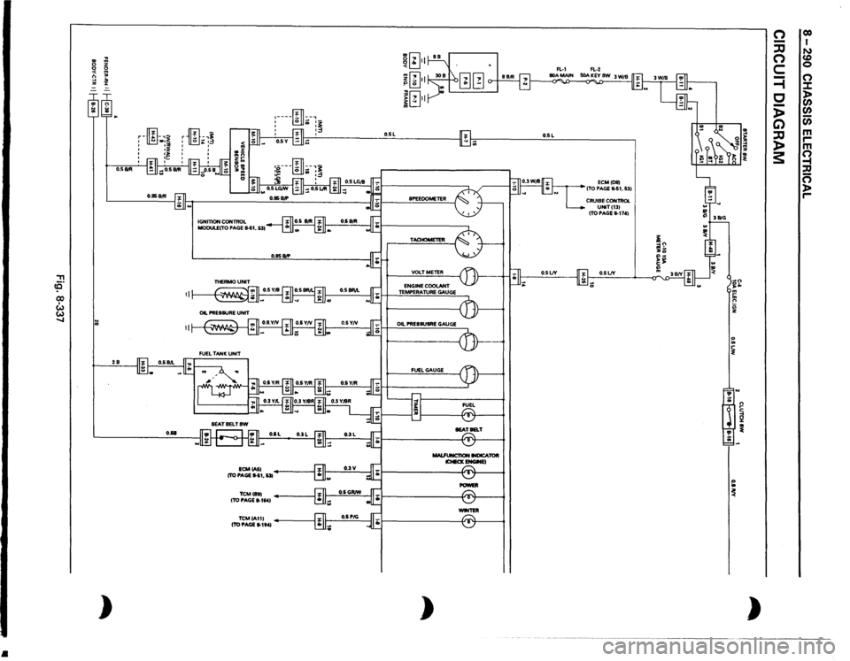
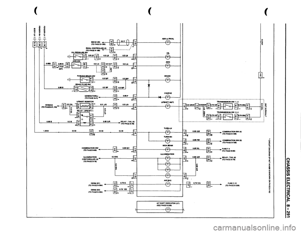
METER AND WARNING/INDICATOR LIGHT
GENERAL DESCRIPTION
The circuit consists of the starter switch, meter assembly, vehicle speed sensor, clutch switch, transmission
switch, lighting switch,
turn signal switch, thermo unit, oil pressure unit, Engine Control Module, fuel tank unit,
4WD
SW, oil pressure switch, parking brake switch, brake fluid switch, seat belt switch and illumination
controller.
The meter ASM contains the speedometer, tachometer, voltmeter, engine coolant temperature gauge, oil
pressure gauge, fuel gauge and warning/indicator lights.
The meter warning/indicator lights and
their bulb sockets are a unit, they are installed from the back of the
speedometer assembly.
Page 1480 of 1928
•
, ce· CX) I w w .....
..
~ m
0
z
0 0 <
m
n
"'
-1
:D
"'
:z:
= ~~ :;; )
O.SIItll 2B
O.&B
ID
-,~
r
-•3
'
.. '
'
' ' IGNITION
CONTROL
MODULECTO
PAGE
S.S1,
531
ECMCASI
(TO PAGE
11-51,
531
TCMihl (TO PAGE
8-1t41
TCMIA111 (TO PAGE
11-1141
~[~} m[i] ~ .:. II
. 0 j[~}l
I'lL,
II"
:----~
.. :~.:,._
:
fill
:~
~~~~ I -··
.!., -
SPEEOOMETER TACHOMETER VOLTMETER ENGINE
COOLANT
TEMPERATURE
GAUGE
OIL PRESSUSRE
GAUGE
FUEL
GAUGE MALFUNCT10N
INDICATOR
lCHECKENGWEI
POWEll -TER
)
O.SL
ECMIDIII
ITO PAGE
11-51,
531
CRUISE
CONTROL UNITI131 ITO PAGE
11-1741
O.SLJY ;;
~ ~ '!' ;;: ~ ~ n ~ ~ )
n -:JJ n c =i c -)> G) :JJ )> 3:
co I N CD 0 (") :.t: > Cl) Cl) Cl) m ,.... m Q , n )> ,....
Page 1481 of 1928
(
I
.. ~ !i:
----
~
........
II
0.858
0.858
0.38
0.85
G/R
1.258
0.58
0.58
0.38
CO-NATIONSW ITOPAGE~
~------_,
cg;c:=~31
0.3 RIG
I
ITO PAGE
8-7S}
:: I~
(
ASS
or RWAL
, • II
OIL ® .awl) ~ -CHARGE
IVT SHIFT
INDICATOR
()(71
{SEE PAGE
11-3351 r:::::-. ~
(
'o .. ~ I J
~~~~
~ ~ ~ '
---------------------------------------------------------
1----
COMBINAliON
8W 1'1
ITO PAGE
11-1011}
1----
CO-NATION
SW(S}
ITO PAGE
11-1011}
~~~~!tEll-SOl ~RELAY;TAILC'I
ITO PAGE
11-78} FUSEC-21 (TO PAGE
8-338}
. n ;;; ~ 0 ~ ;: 3: !il
0
~
::::t
~
)>
)>
(/)
II a;
(/)
..
c;;
~
m
0
r
z
m
... )>
0
~ !
-t ::D
~
c=; )> r co I N CD .....
Page 1485 of 1928
CHASSIS ELECTRICAL 8-295
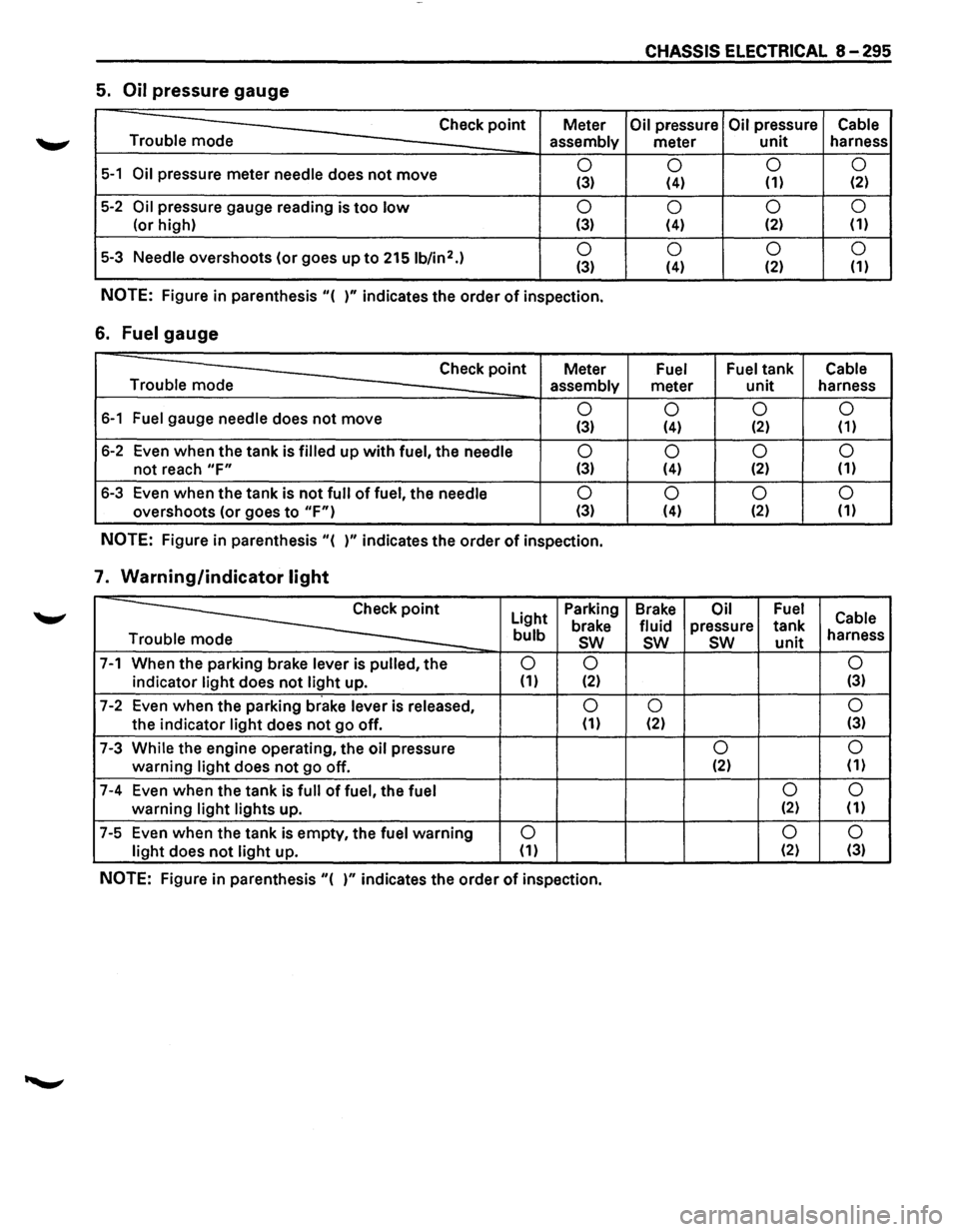
5. Oil pressure gauge
Check point Meter Oil pressure Oil pressure Cable
Trouble mode
assembly meter unit harness
5-1 Oil pressure meter needle does not move 0
0 0
0 (3) (4) (1) (2)
5-2 Oil pressure
gauge reading is too low 0
0 0
0
(or
high) (3) (4) (2) (1)
5-3 Needle overshoots
(or goes up to 2151b/in2.) 0
0 0 0 (3) (4) (2)
(1)
NOTE: Figure
in parenthesis "( )" indicates the order of inspection.
6. Fuel gauge
Check point Meter Fuel Fuel tank Cable
Trouble mode assembly
meter unit harness
6-1 Fuel gauge needle does not move 0
0 0 0 (3) (4) (2) (1)
6-2 Even when the tank is filled up with fuel, the needle 0
0 0
0
not reach "F" (3) (4) (2)
(1)
6-3
Even when the tank is not full of fuel, the needle 0
0 0
0
overshoots (or goes to "F") (3) (4) (2) (1)
NOTE: Figure
in parenthesis "( )" indicates the order of inspection.
7. Warning/indicator light
~
Light Parking
Brake Oil Fuel Cable brake fluid pressure tank bulb sw sw sw unit harness
e
7-1 When the parking brake lever is pulled, the 0 0 0
indicator light does not light up. (1) (2) (3)
7-2 Even
when the parking brake lever is released, 0 0 0
the indicator light does not go off. (1) (2) (3)
7-3 While the engine operating,
the oil pressure 0 0
warning light does not go
off. (2)
(1)
7-4 Even
when the tank is full of fuel, the fuel 0 0
warning light lights
up. (2) (1)
7-5 Even
when the tank is empty, the fuel warning 0 0
0
light does not light up. (1) (2)
(3)
NOTE: Figure in parenthesis "( )" indicates the order of inspection.
Page 1495 of 1928
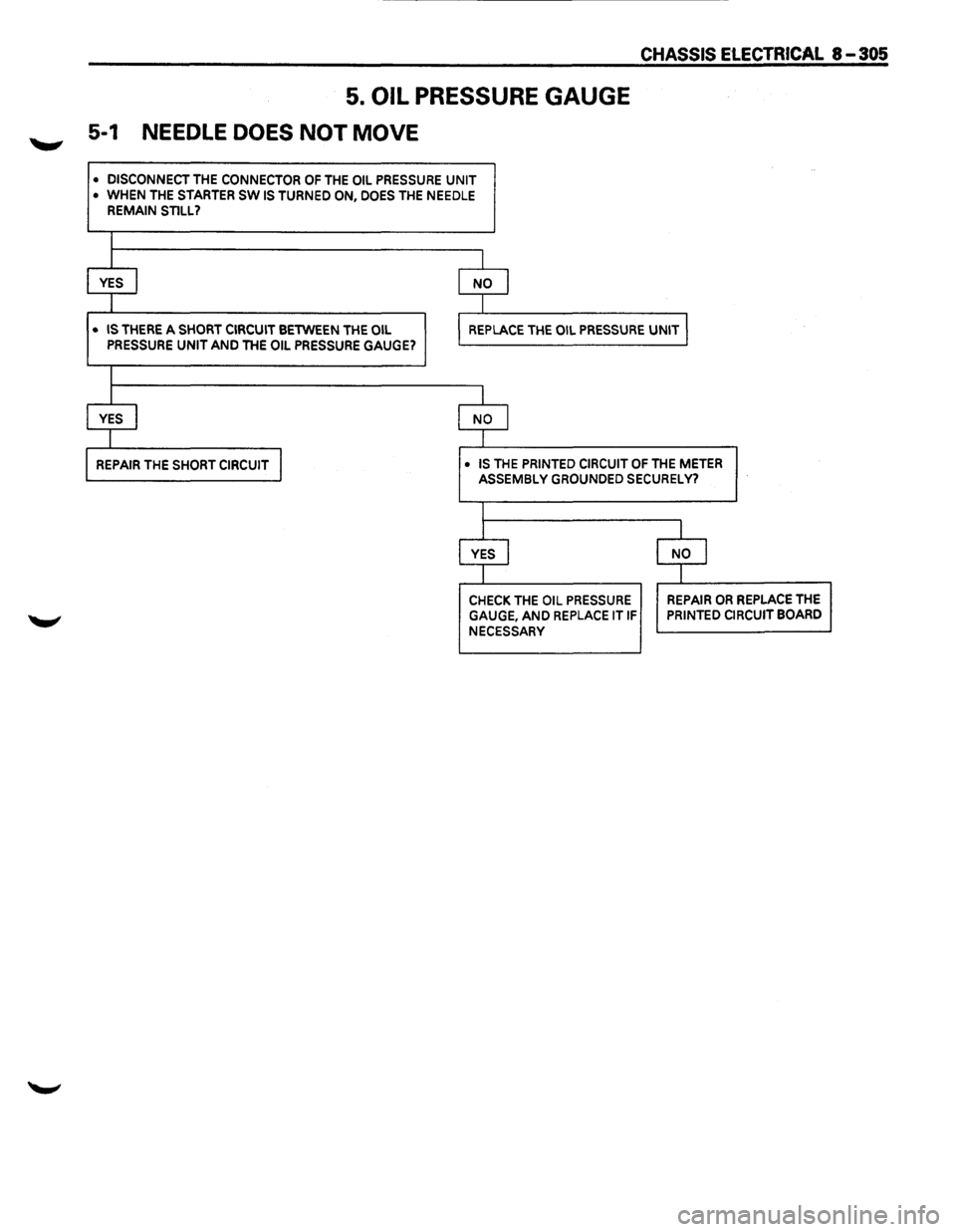
5. OIL PRESSURE GAUGE
5-1 NEEDLE DOES NOT MOVE
• DISCONNECT THE CONNECTOR OF THE OIL PRESSURE UNIT
•
WHEN THE STARTER SW IS TURNED ON, DOES THE NEEDLE REMAIN STILL?
l
J I
YES I NO I
I I
CHASSIS ElECTRICAL 8-305
• IS THERE A SHORT CIRCUIT BETWEEN THE OIL REPLACE THE OIL PRESSURE UNIT I PRESSURE UNIT AND THE OIL PRESSURE GAUGE?
I
I I
YES I NO I
I l
REPAIR THE SHORT CIRCUIT I • IS THE PRINTED CIRCUIT OF THE METER ASSEMBLY GROUNDED SECURELY?
I
I I
YES I NO I
I I
CHECK THE OIL PRESSURE REPAIR OR REPLACE THE
GAUGE, AND REPLACE IT IF PRINTED CIRCUIT BOARD
NECESSARY
Page 1496 of 1928
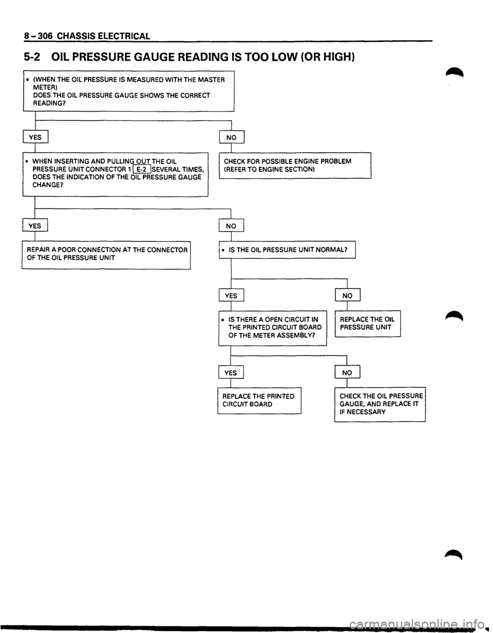
8-306 CHASSIS ELECTRICAL
5-2 OIL PRESSURE GAUGE READING IS TOO LOW (OR HIGH)
• (WHEN THE OIL PRESSURE IS MEASURED WITH THE MASTER METER)
DOES THE OIL PRESSURE GAUGE SHOWS THE CORRECT READING?
I
I
YES I NO I
I
• WHEN INSERTING AND PULLING OUT THE OIL CHECK FOR POSSIBLE ENGINE PROBLEM PRESSURE UNIT CONNECTOR 1 [IDSEVERAL TIMES, (REFER TO ENGINE SECTION) DOES THE INDICATION OF THE OIL PRESSURE GAUGE CHANGE?
I
I
YES I NO I
I
REPAIR A POOR CONNECTION AT THE CONNECTOR • IS THE OIL PRESSURE UNIT NORMAL? I OF THE OIL PRESSURE UNIT
I
YES J NO I
I
• IS THERE A OPEN CIRCUIT IN REPLACE THE OIL
THE PRINTED CIRCUIT BOARD PRESSURE UNIT
OF THE METER ASSEMBLY?
I
YES I NO I
I
REPLACE THE PRINTED CHECK THE OIL PRESSURE
CIRCUIT BOARD GAUGE, AND REPLACE IT
IF NECESSARY