oil ISUZU TROOPER 1995 Workshop Manual
[x] Cancel search | Manufacturer: ISUZU, Model Year: 1995, Model line: TROOPER, Model: ISUZU TROOPER 1995Pages: 1928
Page 1497 of 1928
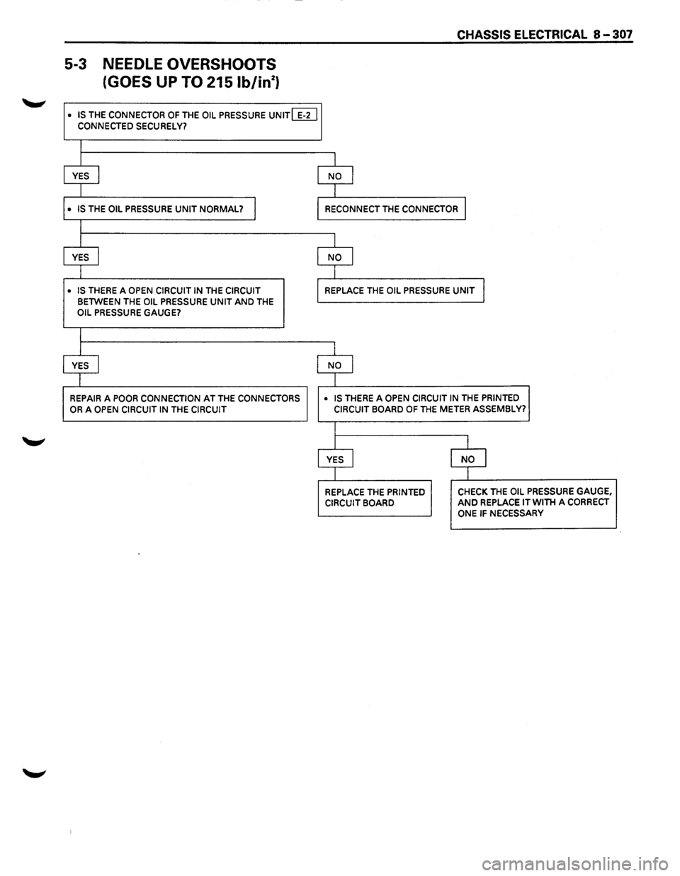
5-3 NEEDLE OVERSHOOTS
(GOES
UP TO 215 lb/in2 )
• IS THE CONNECTOR OF THE OIL PRESSURE UNIT [ILl CONNECTED SECURELY?
I
I
YES I
I
• IS THE OIL PRESSURE UNIT NORMAL? I
I
I
YES
I
• IS THERE A OPEN CIRCUIT IN THE CIRCUIT
BETWEEN THE OIL PRESSURE UNIT AND THE OIL PRESSURE GAUGE?
I
I
YES I
I
REPAIR A POOR CONNECTION AT THE CONNECTORS
OR A OPEN CIRCUIT IN THE CIRCUIT
CHASSIS ELECTRICAL 8 -307
I
NO I
I
RECONNECT THE CONNECTOR I
I
NO I
I
REPLACE THE OIL PRESSURE UNIT I
I
NO I
I
• IS THERE A OPEN CIRCUIT IN THE PRINTED CIRCUIT BOARD OF THE METER ASSEMBLY?
I
I
I
YES I NO j
I I
REPLACE THE PRINTED CHECK THE OIL PRESSURE GAUGE,
CIRCUIT BOARD AND REPLACE IT WITH A CORRECT
ONE IF NECESSARY
Page 1503 of 1928
CHASSIS ELECTRICAL 8-313
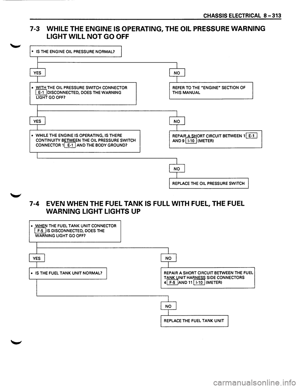
7-3 WHILE THE ENGINE IS OPERATING, THE OIL PRESSURE WARNING
LIGHT WILL
NOT GO OFF
• IS THE ENGINE OIL PRESSURE NORMAL? I
I
I I
YES I NO I
I I
• WITH THE OIL PRESSURE SWITCH CONNECTOR REFER TO THE "ENGINE" SECTION OF
~DISCONNECTED, DOES THE WARNING THIS MANUAL LIGHT GO OFF?
I
I I
YES I NO I
I I
• WHILE THE ENGINE IS OPERATING, IS THERE REPAIRctTIORT CIRCUIT BETWEEN 1 [ill CONTINUITY BETWEEN THE OIL PRESSURE SWITCH AND 9 1-10 (METER) CONNECTOR 1~ AND THE BODY GROUND?
I
I
NO I
I
REPLACE THE OIL PRESSURE SWITCH I
7-4 EVEN WHEN THE FUEL TANK IS FULL WITH FUEL, THE FUEL
WARNING LIGHT LIGHTS UP
• WHEN THE FUEL TANK UNIT CONNECTOR
[EIJ1s DISCONNECTED, DOES THE WARNING LIGHT GO OFF?
l
YES I NO I
I
• IS THE FUEL TANK UNIT NORMAL? I REPAIR A SHORT CIRCUIT BETWEEN THE FUEL
TiNK JNIT HARNESS SIDE CONNECTORS 4 F-5 AND 11 [I!QJ (METER)
1
NO I
I
REPLACE THE FUEL TANK UNIT I
Page 1506 of 1928
8-316 CHASSIS ELECTRICAL
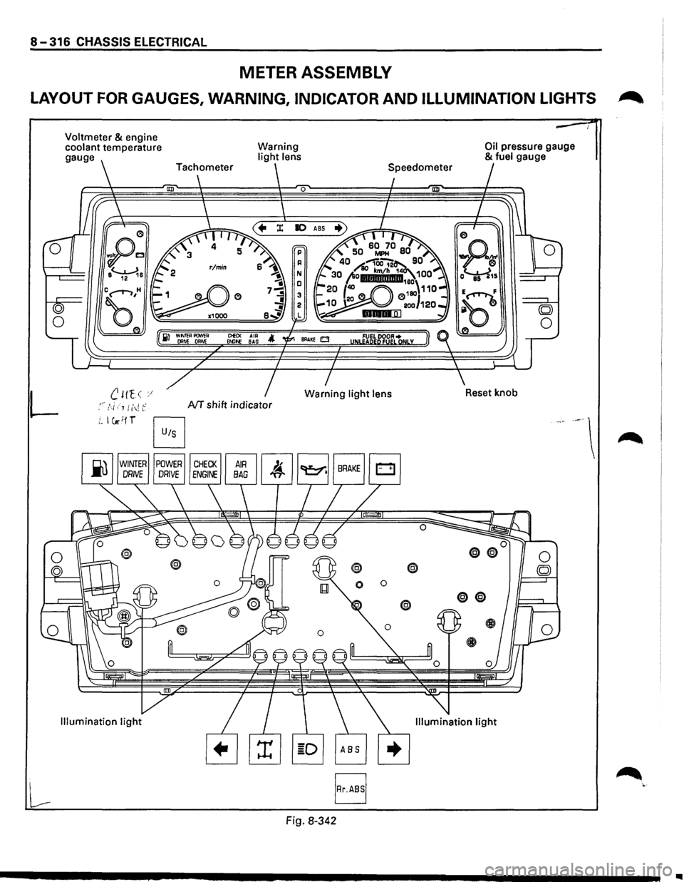
METER ASSEMBLY
LAYOUT FOR GAUGES, WARNING, INDICATOR AND ILLUMINATION LIGHTS .~
L
Voltmeter & engine
coolant temperature
gauge
B
Warning light lens
0
ClEO< AIR Et.llf>E BAG
NT shift indicator
Fig. 8-342
@ @
0 0
Oil pressure gauge & fuel gauge
..
Page 1507 of 1928
CHASSIS ELECTRICAL 8-317
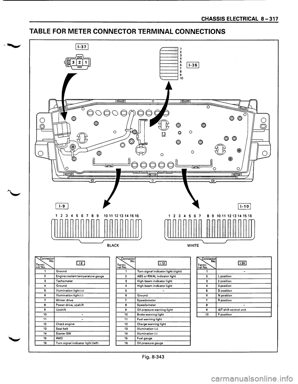
TABLE FOR METER CONNECTOR TERMINAL CONNECTIONS
~-""""""', 1----""'12 1----""'1! 6 1----l 6 [Iill
1----""'1 ~ 9 1---""'l,o
®
0 0
0
® @
0 0 ~
~m© © © © ©'--m ~~0
0 !III
1 2 3 4 5 6 7 8 9 1011 1213141516 1 2 3 4 56 7 8 9 10111213141516
w~~~~~~~~ ~~~~~~m rn~~~~~~ ~~nn~~m
~ I J BLACK WHITE
~r o. DTI -na No. ~
. IJJ:Q] -
. ~ [ill] . -. 1 Ground 1 Turn
signal indicator light (right)
1 -2 Engine coolant temperature gauge 2 ABS or RWAL indicator light 2 L
position
3 Tachometer 3 High-beam indicator light 3 2 position 4
Ground
4 High-beam
indicator light 4 3 position 6 Illumination light (+I 5 -5 D position
6 Illumination light(-) 6 Ground 6 N position 7 Winter drive 7 Speedometer 7 R position 8 Power drive, upshift 8 Speedometer 8 -9 Upshift 9 Oil pressure warning light 9 AfT shift control unit 10 -10 Brake warning light 10 P position 11 -11 Fuel warning light 12 Check engine 12 Charge warning light 13 Seat belt 13 Illumination (+) 14 StarterSW 14 Illumination (-) 15 4WD 15 Fuel gauge 16 Turn signal indicator light (left) 16 Oil pressure gauge
Fig. 8-343
Page 1508 of 1928
8-318 CHASSIS ELECTRICAL
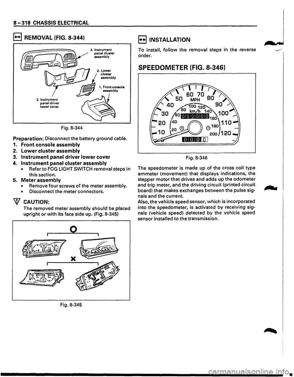
B REMOVAL (FIG. 8-344)
3. Instrument
panel driver lower cover
Fig. 8-344
4. Instrument
panel cluster
assembly
Preparation: Disconnect the battery ground cable.
1. Front console assembly
2. Lower cluster assembly
3. Instrument panel driver lower cover
4. Instrument panel cluster assembly
• Refer to FOG LIGHT SWITCH removal steps in
this section.
5. Meter assembly
• Remove four screws of the meter assembly.
•
Disconnect the meter connectors.
W CAUTION:
The removed meter assembly should be placed
upright or with its face side up. (Fig. 8-345)
0
)(
Fig. 8-345
B INSTALLATION
To install, follow the removal steps in the reverse
order.
SPEEDOMETER (FIG. 8-346)
Fig. 8-346
The speedometer is made up
of the cross coil type
ammeter (movement)
that displays indications, the
stepper
motor that drives and adds up the odometer
and
trip meter, and the driving circuit (printed circuit
board) that makes exchanges between the
pulse sig
nals and the current.
Also, the vehicle speed sensor, which is incorporated
into the speedometer, is activated
by receiving sig
nals (vehicle speed) detected by the vehicle speed
sensor
installed to the transmission.
•
Page 1511 of 1928
3. Meter
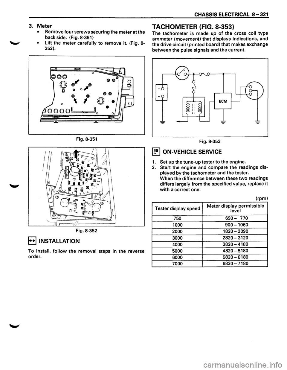
• Remove four screws securing the meter at the
back side. (Fig.
8-351)
• Lift the meter carefully to remove it. (Fig. 8-
352).
0
q;J"' 0
0 0 0,
0 0
0 I
Fig. 8-351
Fig. 8-352
E) INSTALLATION
00
0
To install, follow the removal steps in the reverse
order.
CHASSIS ELECTRICAL 8-321
TACHOMETER (FIG. 8-353)
The tachometer is made up of the cross coil type
ammeter (movement) that displays indications, and
the drive circuit (printed board)
that makes exchange
between the
pulse signals and the current.
Fig.
8-353
(1!1 ON-VEHICLE SERVICE
1. Set up the tune-up tester to the engine.
2. Start the engine and compare the readings dis
played by the tachometer and the tester.
When the difference between these
two readings
differs
largely from the specified value, replace it
with a correct one.
(rpm)
Tester
display speed Meter
display permissible level
750 690-770
1000
900-1060
2000 1820-2090
3000 2820-3120
4000 3820-4180
5000 4820-5180
6000 5820-6180
7000 6820-7180
Page 1515 of 1928
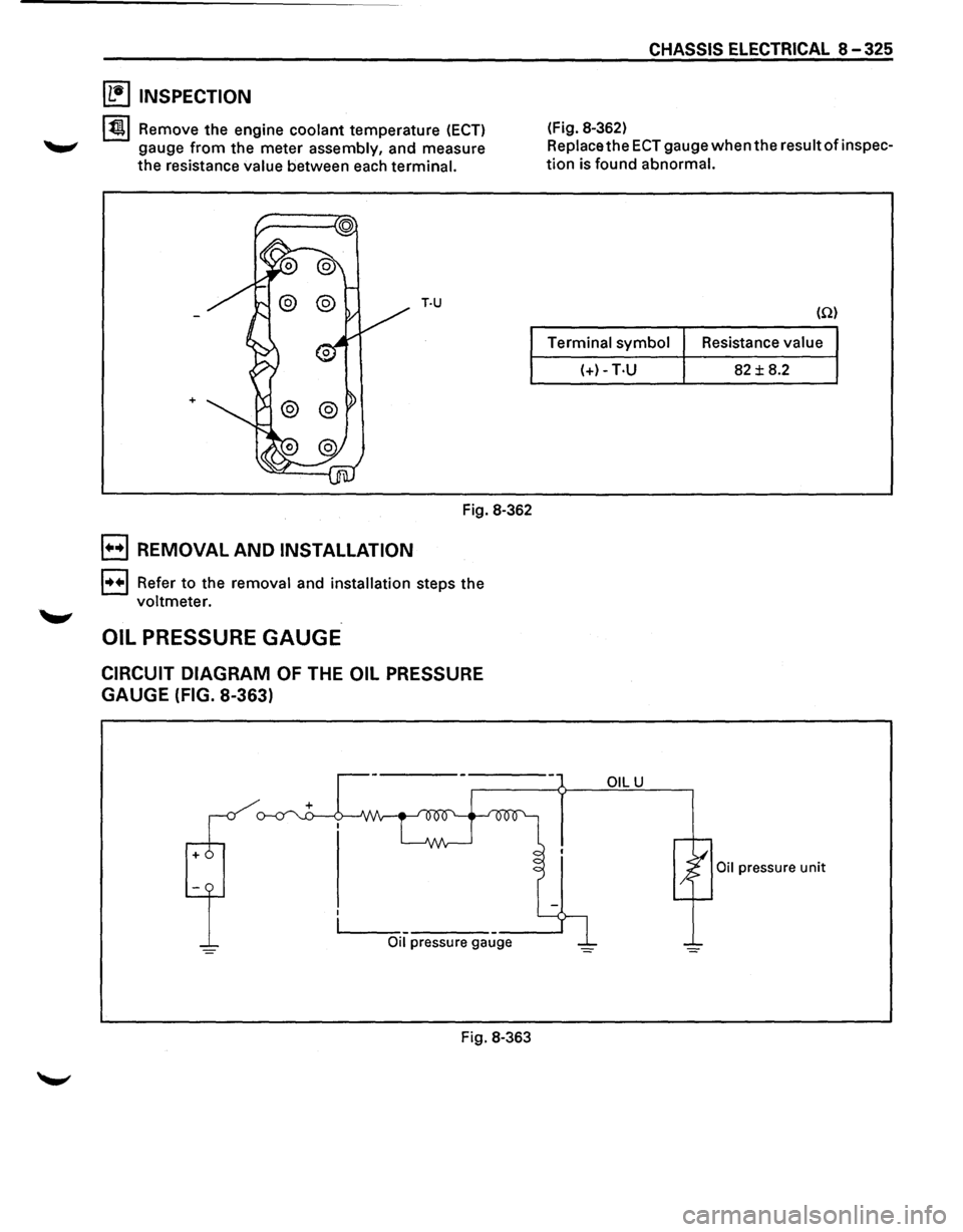
~ INSPECTION
131 Remove the engine coolant temperature (ECT)
gauge from the meter assembly, and measure
the resistance value between each terminal.
T·U
+
Fig. 8-362
E) REMOVAL AND INSTALLATION
1••1 Refer to the removal and installation steps the
voltmeter.
OIL PRESSURE GAUGE
CIRCUIT DIAGRAM OF THE OIL PRESSURE
GAUGE (FIG. 8-363)
CHASSIS ELECTRICAL 8 -325
(Fig. 8-362)
Replace the
ECT gauge when the result of inspec
tion is found abnormal.
(Q)
Terminal symbol Resistance
value
(+)-T·U 82 ± 8.2
OILU
Oil pressure unit
,______ _ __ ___.
Oil pressure gauge
Fig. 8-363
Page 1516 of 1928
8-326 CHASSIS ELECTRICAL
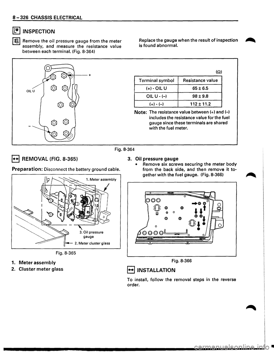
~ INSPECTION
l~l Remove the oil pressure gauge from the meter
assembly, and measure the resistance value
between each terminal. (Fig. 8-364)
Replace the gauge when the result of inspection ~
is found abnormal.
(Q)
Terminal symbol Resistance value
(+)-OIL U 65± 6.5
OIL U-(-) 98±9.8
{+)-{-) 112± 11.2
Note: The resistance value between {+)and(-)
includes the resistance value for the fuel
gauge since these terminals are shared
with the
fuel meter.
Fig. 8-364
B REMOVAL (FIG. 8-365)
Preparation: Disconnect the battery ground cable.
gauge
2. Meter cluster glass
Fig. 8-365
1.
Meter assembly
2. Cluster meter glass
3. Oil pressure gauge
• Remove six screws securing the meter body
from the back side, and then remove it to
gether with the fuel gauge. (Fig. 8-366)
Fig. 8-366
E) INSTALLATION
To install, follow the removal steps in the reverse
order.
•
Page 1517 of 1928
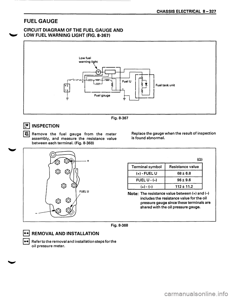
CHASSIS ELECTRICAL 8 -327
FUEL GAUGE
CIRCUIT DIAGRAM OF THE FUEL GAUGE AND
'--"' LOW FUEL WARNING LIGHT (FIG. 8-367)
Low fuel
Fuel gauge
Fig. 8-367
~ INSPECTION
lt!tl Remove the fuel gauge from the meter
assembly, and measure the resistance value
between each terminal. (Fig. 8-368) Replace
the gauge when the result
of inspection
is found abnormal.
(Q)
Terminal symbol Resistance
value
(+)-FUEL U
68± 6.8
FUEL U-(-) 96± 9.6
(+)- (-)
112 ± 11.2
Note: The resistance value between(+) and H
includes the resistance value
for the oil
pressure gauge since these terminals are
shared with the
oil pressure gauge.
Fig. 8-368
B REMOVAL AND INSTALLATION
1•,.1 Refer to the removal and installation steps for the
oil pressure meter.
Page 1521 of 1928
![ISUZU TROOPER 1995 Workshop Manual OIL PRESSURE UNIT
(1!] INSPECTION
Measure the resistance value ofthe oil pressure unit
with the circuit tester. (Fig. 8-377)
Replace the
unit when the result of inspection is found
abnorm](/img/61/57183/w960_57183-1520.png "ISUZU TROOPER 1995 Workshop Manual OIL PRESSURE UNIT
(1!] INSPECTION
Measure the resistance value ofthe oil pressure unit
with the circuit tester. (Fig. 8-377)
Replace the
unit when the result of inspection is found
abnorm")
OIL PRESSURE UNIT
(1!] INSPECTION
Measure the resistance value ofthe oil pressure unit
with the circuit tester. (Fig. 8-377)
Replace the
unit when the result of inspection is found
abnormal.
Pressure
(kPa)
Resistance value (Q)
Fig. 8-377
OIL PRESSURE SWITCH
(1!] INSPECTION
98 981
81 30
I~~ Check the continuity between the switch termi
nal and the body ground with the engine at idle.
(Fig. 8-378)
Replace the switch when the result
of inspection
is
found abnormal.
Fig. 8-378
CHASSIS ELECTRICAL 8-331
(1!] CIRCUIT INSPECTION (FIG. 8-379)
Fig. 8-379
1. Start the engine.
2. When disconnecting the oil pressure switch con
nector then connecting the harness side connec
tor to the ground, check to see if the oil pressure
warning light lights up.
When the
light will not light up, check the circuit
between the meter and the oil pressure switch,
and repair
an open circuit if necessary.
FUEL TANK UNIT
The tank unit varies the internal resistance according
to the float position (fluid level) to operate the fuel
meter needle.
It is also designed
to warn the driver of low fuel level
by illuminating the fuel warning light. (Fig. 8-380)
Fig. 8-380