torque ISUZU TROOPER 1995 Workshop Manual
[x] Cancel search | Manufacturer: ISUZU, Model Year: 1995, Model line: TROOPER, Model: ISUZU TROOPER 1995Pages: 1928
Page 1157 of 1928
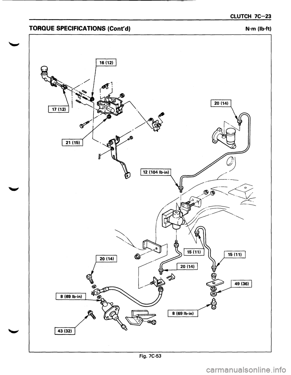
CLUTCH 7C-23
TORQUE SPECIFICATIONS (Cont'd) N·m (lb·ft)
16 (12)
12
(104 lb·in)
8 (691b·in)
8 (691b·in)
Fig. 7C-53
Page 1159 of 1928
TRANSFER CASE 7D-1
SECTION 70
TRANSFER CASE
w CAUTION:
When fasteners are removed, always reinstall them at the same location from which they were removed. If a
fastener needs
to be replaced, use the correct part number fastener for that application. If the correct part
number is not available, a fastener
of equal size and strength (or stronger) may be used. Fasteners that are
not reused, and those requiring thread locking compound, will
be called out. The correct torque values must
be used when installing fasteners that require torque.
If the above conditions are not followed, parts or
system damage could result.
CONTENTS
General Description ................... 7D-1
Construction . . . . . . . . . . . . . . . . . . . . . . . . . 7D-2
On-Vehicle Service .................... 7D-3
Transfer
Case (A/T) .................. 7D-3
Transfer Rear
Oil Seal ................ 7D-5
Unit Repair ........................... 7D-8
Transfer
Case Assembly (AfT) ........ 7D-8
Transfer Rear
Case Assembly . .
. . . . . 7D-11
Detent, Shift Arm, And
Interlock Pin (Transfer
Case Assembly) . .
. . . . . . . . . . . . . . . . . . 7D-14 Transfer
Case
Assembly . .
. . . . . . . . . .
7D-17
Main Data And Specifications . . . . . . . .
70-29
General
Specifications . .
. . . . . . . . . . . .
70-29
Torque
Specifications ............... 7D-30
Special Tools
........................ 7D-32
GENERAL DESCRIPTION
The transfer case is used to provide a means of
providing power flow to the front axle. The transfer
case also provides a means of disconnecting the front
axle, providing better fuel economy and quieter
operation when the vehicle is driven
on improved
roads where four wheel drive is not required.
In
addition, the transfer case provides an additional gear
reduction when placed in low range, which
is useful
when difficult off-road conditions are encountered. A
floor mounted shift lever is used to select the
operating range. When four wheel drive has been
selected, the four wheel drive indicator light is
designed to come
on when the front axle has been
engaged.
Page 1162 of 1928
70-4 TRANSFER CASE
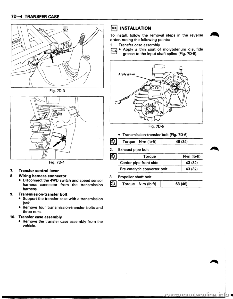
Fig. 70-3
Fig. 70-4
7. Transfer control lever
8. Wiring harness connector
• Disconnect the 4WD switch and speed sensor
harness connector from the transmission
harness.
9. Transmission-transfer bolt
• Support the transfer case with a transmission
jack.
• Remove four transmission-transfer bolts and
three nuts.
10. Transfer case assembly
• Remove the transfer case assembly from the
vehicle.
1••1 INSTALLATION
To install, follow the removal steps in the reverse ~
order, noting the following points:
1. Transfer case assembly
r;:;J • Apply a thin coat of molybdenum disulfide
D grease to the input shaft spline (Fig. 70-5).
Fig. 70-5
• Transmission-transfer bolt (Fig. 70-6)
1~1 Torque N·m (lb·ft)
2. Exhaust pipe bolt
1~1 Torque
Center pipe front side
Pre-catalytic converter bolt
3. Propeller shaft bolt
1~1 Torque N·m (lb·ft)
46 (34)
N·m (lb·ft)
43 (32)
43 (32)
63 (46)
•
Page 1163 of 1928
46/34
30
T/F Case
T/M case
+/F Case
T/M Case
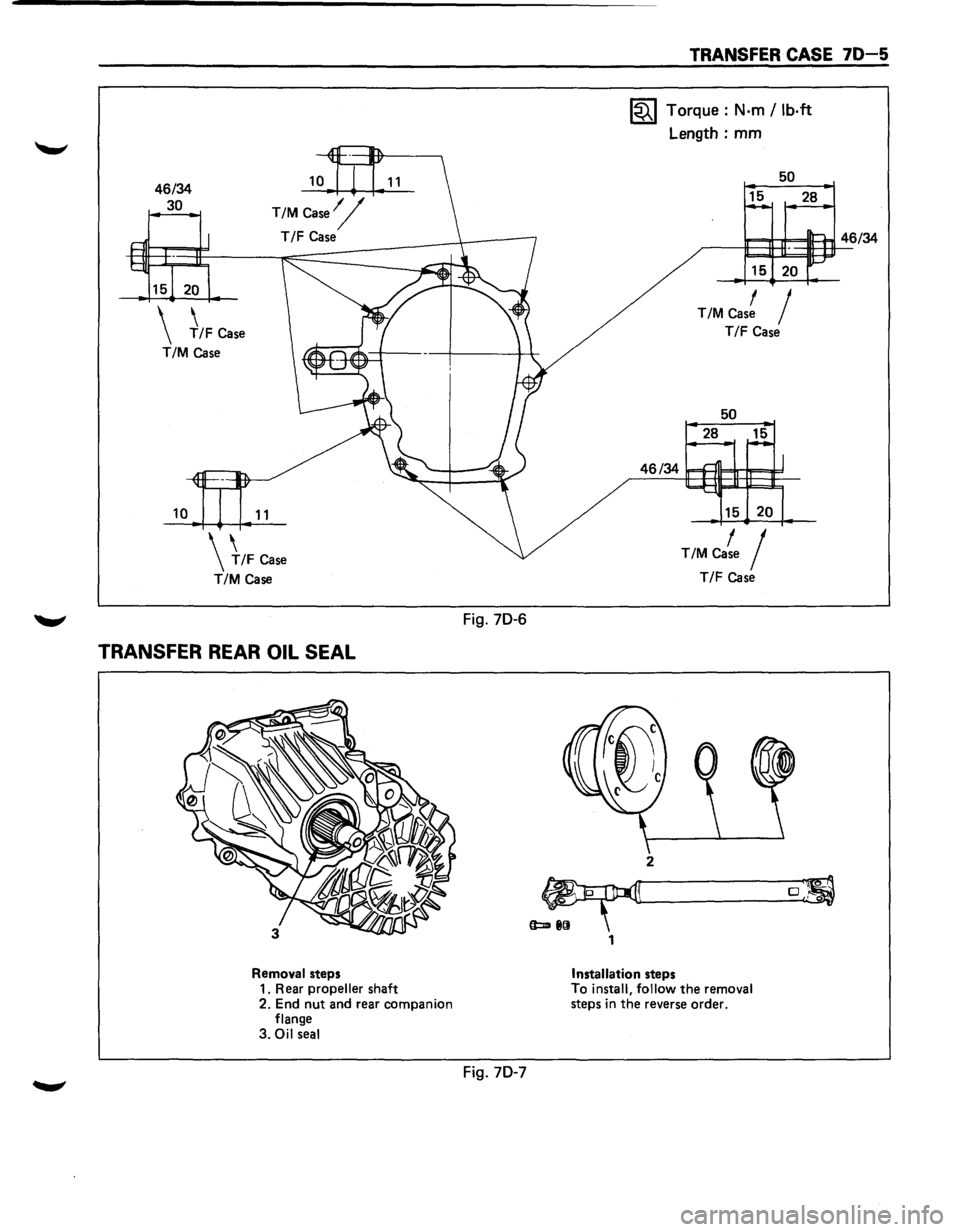
TRANSFER REAR OIL SEAL
Removal steps
1. Rear propeller shaft
2. End nut and rear companion
flange
3.
Oil seal
Fig. 70-6
Fig. 70-7
1
TRANSFER CASE 70-5
1~1 Torque: N·m /lb·ft
Length: mm
50
15 28
15 20
T/M Cas! I
T/F Case
50
28 15
T/M Ca~e I
T/F case
2
0 ,""o
Installation steps
To install, follow the removal
steps in the reverse order.
Page 1164 of 1928
70-6 TRANSFER CASE
EJ REMOVAL
1. Rear propeller shaft
• Disconnect the rear propeller shaft from the
transfer case side.
2. End nut and rear companion flange.
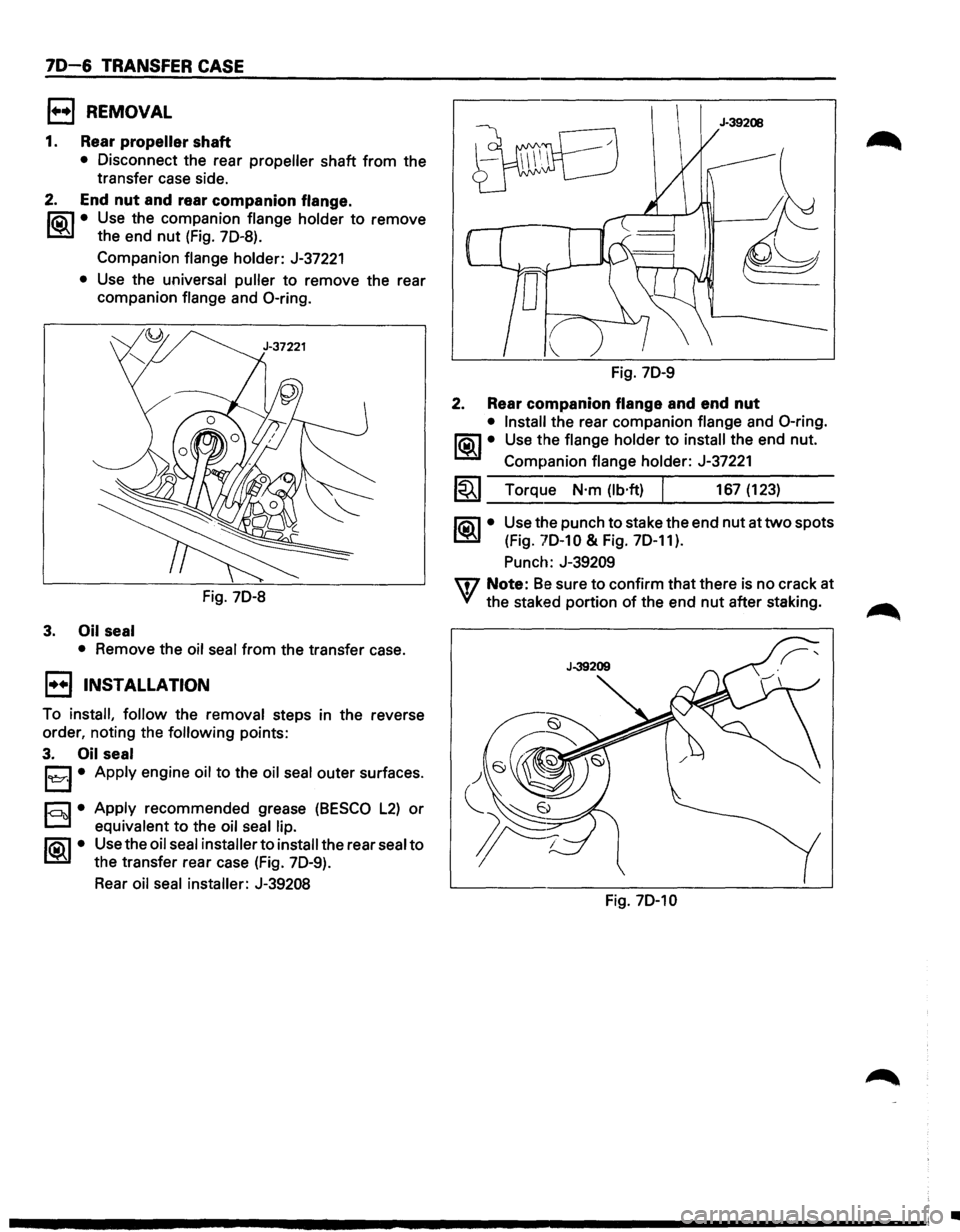
li5\l • Use the companion flange holder to remove
~ the end nut (Fig. 70-8).
Companion flange holder: J-37221
• Use the universal puller to remove the rear
companion flange and 0-ring.
Fig. 70-8
3. Oil seal
•
Remove the oil seal from the transfer case.
1••1 INSTALLATION
To install, follow the removal steps in the reverse
order, noting the
following points:
3. Oil seal
l
D equivalent to the oil seal lip.
li5\l • Use the oil seal installer to install the rear seal to
~ the transfer rear case (Fig. 70-9).
Rear oil seal installer: J-39208
Fig. 70-9
2. Rear companion flange and end nut
• Install the rear companion flange and 0-ring.
l<9l..l• Use the flange holder to install the end nut.
Companion flange holder:
J-37221
1~1 Torque N·m (lb·ft) I 167 (123)
~·
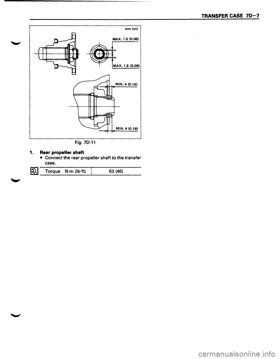
Use the punch to stake the end nut at two spots
(Fig.
70-10 & Fig. 70-11).
Punch: J-39209
m Note: Be sure to confirm that there is no crack at
VI the staked portion of the end nut after staking.
Fig. 70-10
•
Page 1165 of 1928
TRANSFER CASE 70-7
mm(in)
MAX. 1.5 (0.06)
MAX. 1.5 (0.06)
MIN. 4 (0.16)
MIN. 4 (0.16)
Fig. 70-11
1. Rear propeller shaft
• Connect the rear propeller shaft to the transfer
case.
l~l Torque N·m (lb·ft) 63 (46)
Page 1167 of 1928
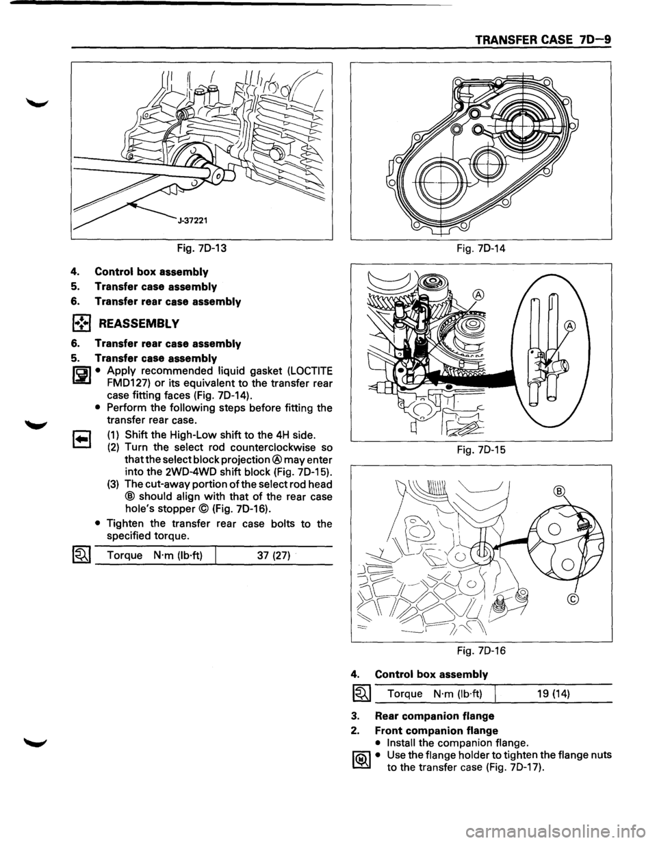
Fig. 70-13
4.
Control box assembly
5. Transfer case assembly
6. Transfer rear case assembly
l•!•l REASSEMBLY
6. Transfer rear case assembly
5. Transfer case assembly
1'61 • Apply recommended liquid gasket (LOCTITE
Li!:l FM0127) or its equivalent to the transfer rear
case fitting faces (Fig. 70-14).
• Perform the following steps before fitting the
transfer rear case.
1 .. 1 (1) Shift the High-Low shift to the 4H side.
(2) Turn the select rod counterclockwise so
that the select block projection® may enter
into the 2W0-4WO shift
block (Fig. 70-15).
(3) The cut-away portion of the select rod head
@ should align with that of the rear case
hole's stopper© (Fig. 70-16).
• Tighten the transfer rear case bolts to the
specified torque.
1~1 Torque N·m (lb·ft) 37 (27)
TRANSFER CASE 70-9
Fig. 70-14
Fig. 70-15
Fig. 70-16
4. Control box assembly
~~~ Torque N·m (lb·ft) 19 (14)
3. Rear
companion flange
2. Front companion flange
• Install
the companion flange.
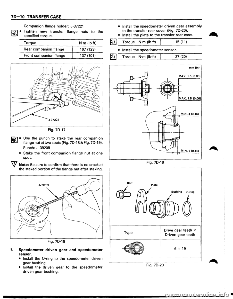
l"iC\l • Use the flange holder to tighten the flange nuts
~ to the transfer case (Fig. 70-17).
Page 1168 of 1928
70-10 TRANSFER CASE
~·
Companion flange holder: J-37221
Tighten
new transfer flange nuts to the
specified torque.
Torque
N·m (lb·ft)
Rear companion flange 167(123)
Front companion
flange 137 (101)
Fig. 70-17
1®..1• Use the punch to stake the rear companion
flange nut at two spots (Fig. 7D-18 & Fig. 70-19).
Punch: J-39209
• Stake the front companion flange nut at one
spot.
W Note: Be sure to confirm that there is no crack at
the staked portion of the flange nut after staking.
Fig. 70-18
1. Speedometer driven gear and speedometer
sensor.
• Install the 0-ring to the speedometer driven
gear bushing.
• Install the driven gear to the speedometer
driven gear bushing.
• Install the speedometer driven gear assembly
to the transfer rear cover (Fig. 7D-20).
• Install the plate to the transfer rear case.
~~~ Torque N·m(lb·ft) J 15(11)
• Instal!! the speedometer sensor.
I~I __ T_o_rq~u_e __ N_·_m_(_lb_·ft_l~ ______ 2_7_(2_0_) ____ _
Bolt
~
Type
•
' . '
Fig. 70-19
Plate
Fig. 7D-20
mm (in)
MAX. 1.5 10.06)
MAX. 1.5 (0.06)
MIN. 4 (0.16)
MIN. 4 (0.161
Drive gear teeth X
Driven gear teeth
6
X 19
•
Page 1174 of 1928
70-16 TRANSFER CASE
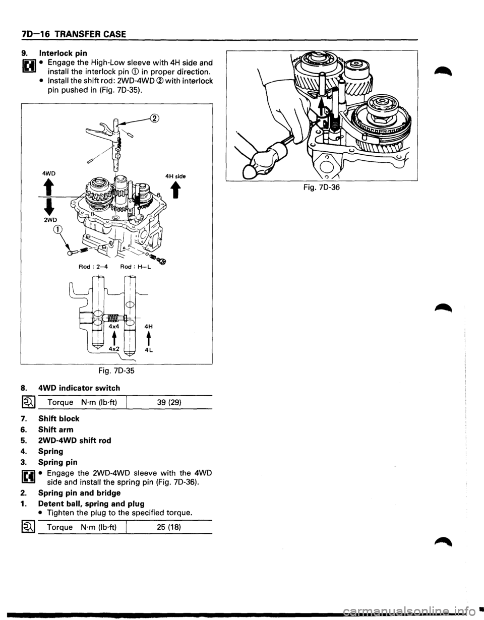
9. Interlock pin
r.:il • Engage the High-Low sleeve with 4H side and
U install the interlock pin CD in proper direction.
• Install the shift rod: 2W0-4WO ®with interlock
pin pushed in (Fig. 70-35).
Fig. 70-35
8. 4WD indicator switch
~~~ Torque N·m (lb·ft)
7. Shift block
6. Shift arm
5. 2WD-4WD shift rod
4. Spring
3. Spring pin
4H side
t
39 (29)
flil1 • Engage the 2W0-4WO sleeve with the 4WD
U side and install the spring pin (Fig. 70-36).
2. Spring pin and bridge
1. Detent ball, spring and plug
• Tighten the plug to the specified torque.
~~~ Torque N·m (lb·ft) I 25 (18)
Fig. 70-36
•
Page 1183 of 1928
IMITI
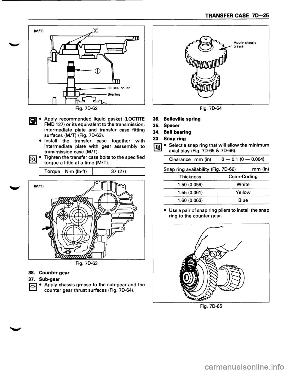
Fig. 70-62
~~~· Apply recommended liquid gasket (LOCTITE
FMO 127) or its equivalent to the transmission,
intermediate
plate and transfer case fitting
surfaces (M/T) (Fig. 70-63).
• Install the transfer case together with
intermediate plate with gear asssembly to
transmission case (M/T).
~~~· Tighten the transfer case bolts to the specified
torque a
little at a time (M/T).
Torque
N·m (lb·ft)
38. Counter gear
37. Sub-gear
Fig. 70-63
37 (27)
§!• Apply chassis grease to the sub-gear and the
counter gear thrust surfaces (Fig. 70-64).
TRANSFER CASE 70-25
36. Belleville spring
35. Spacer
34.
Ball bearing
33.
Snap ring
Fig. 70-64
Apply chassis
grease
rfil • Select a snap ring that will allow the minimum
l!l:.l axial play (Fig. 70-65 & 70-66).
Clearance mm (in) I 0 -0.1 (0 -0.004)
Snap ring availability (Fig. 70-66) mm (in)
Thickness
Color-Coding
1.50 (0.059) White
1.55 (0.061)
Yellow
1.60 (0.063) Blue
•
Use a pair of snap ring pliers to install the snap
ring to the counter gear.
Fig. 70-65