lock ISUZU TROOPER 1995 Workshop Manual
[x] Cancel search | Manufacturer: ISUZU, Model Year: 1995, Model line: TROOPER, Model: ISUZU TROOPER 1995Pages: 1928
Page 1167 of 1928
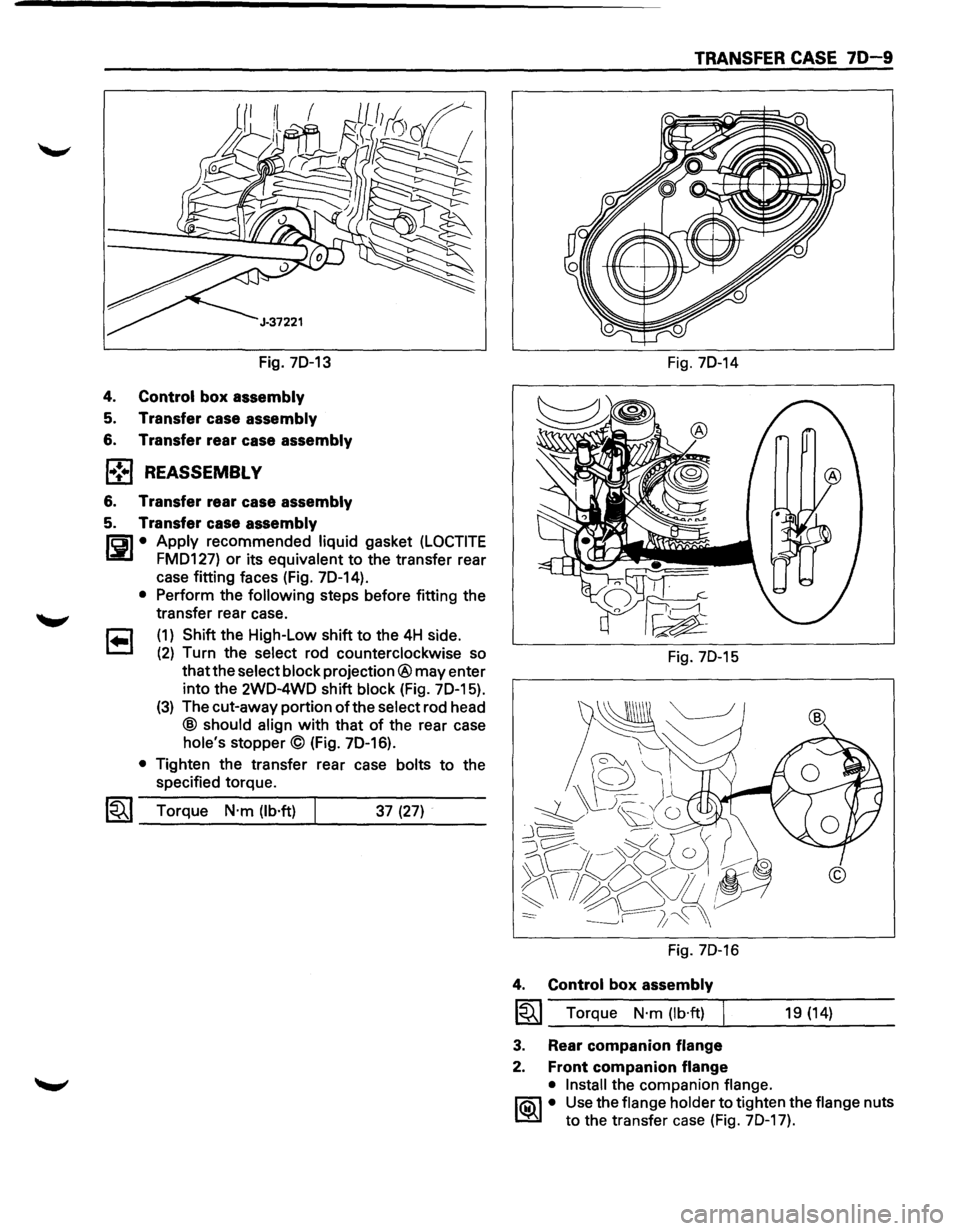
Fig. 70-13
4.
Control box assembly
5. Transfer case assembly
6. Transfer rear case assembly
l•!•l REASSEMBLY
6. Transfer rear case assembly
5. Transfer case assembly
1'61 • Apply recommended liquid gasket (LOCTITE
Li!:l FM0127) or its equivalent to the transfer rear
case fitting faces (Fig. 70-14).
• Perform the following steps before fitting the
transfer rear case.
1 .. 1 (1) Shift the High-Low shift to the 4H side.
(2) Turn the select rod counterclockwise so
that the select block projection® may enter
into the 2W0-4WO shift
block (Fig. 70-15).
(3) The cut-away portion of the select rod head
@ should align with that of the rear case
hole's stopper© (Fig. 70-16).
• Tighten the transfer rear case bolts to the
specified torque.
1~1 Torque N·m (lb·ft) 37 (27)
TRANSFER CASE 70-9
Fig. 70-14
Fig. 70-15
Fig. 70-16
4. Control box assembly
~~~ Torque N·m (lb·ft) 19 (14)
3. Rear
companion flange
2. Front companion flange
• Install
the companion flange.
l"iC\l • Use the flange holder to tighten the flange nuts
~ to the transfer case (Fig. 70-17).
Page 1169 of 1928
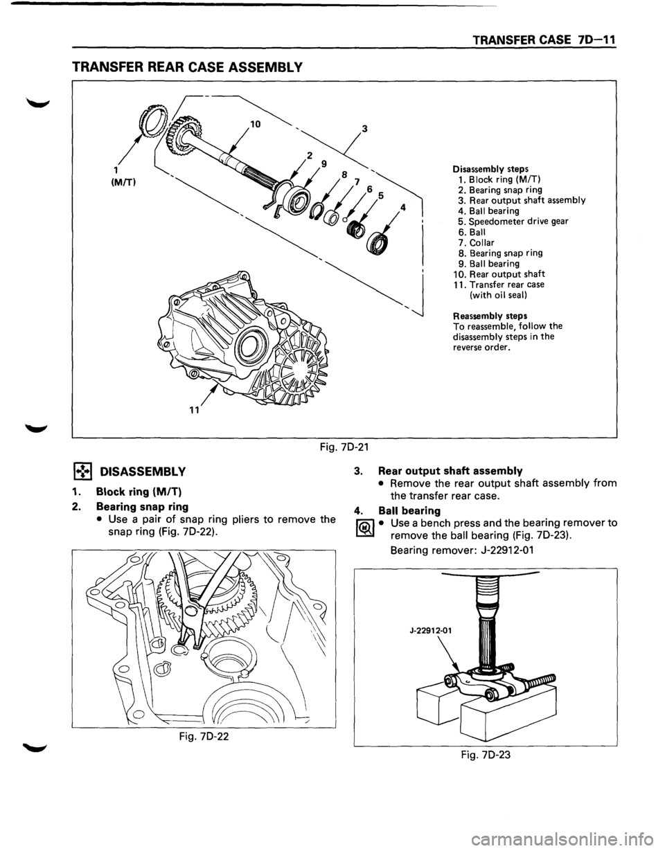
TRANSFER REAR CASE ASSEMBL V
TRANSFER CASE 70-11
Disassembly steps 1. Block ring (M/T)
2. Bearing snap ring
3. Rear
output shaft assembly
4. Ball bearing
5. Speedometer drive gear
6. Ball
7.
Collar 8. Bearing snap ring
9. Ball bearing
10. Rear output shaft 11. Transfer rear case
(with oil seal)
Reassembly steps
To reassemble, follow the disassembly steps in the reverse order.
Fig. 70-21
l•!•l DISASSEMBLY
1. Block ring (MIT)
2. Bearing snap ring
• Use a pair of snap ring pliers to remove the
snap ring (Fig. 70-22).
Fig. 70-22
3. Rear output shaft assembly
• Remove the rear output shaft assembly from
the transfer rear case.
4. Ball bearing
I'Qi) • Use a bench press and the bearing remover to
~ remove the ball bearing (Fig. 70-23).
Bearing remover:
J-22912-01
J-22912-01
Fig. 70-23
Page 1171 of 1928
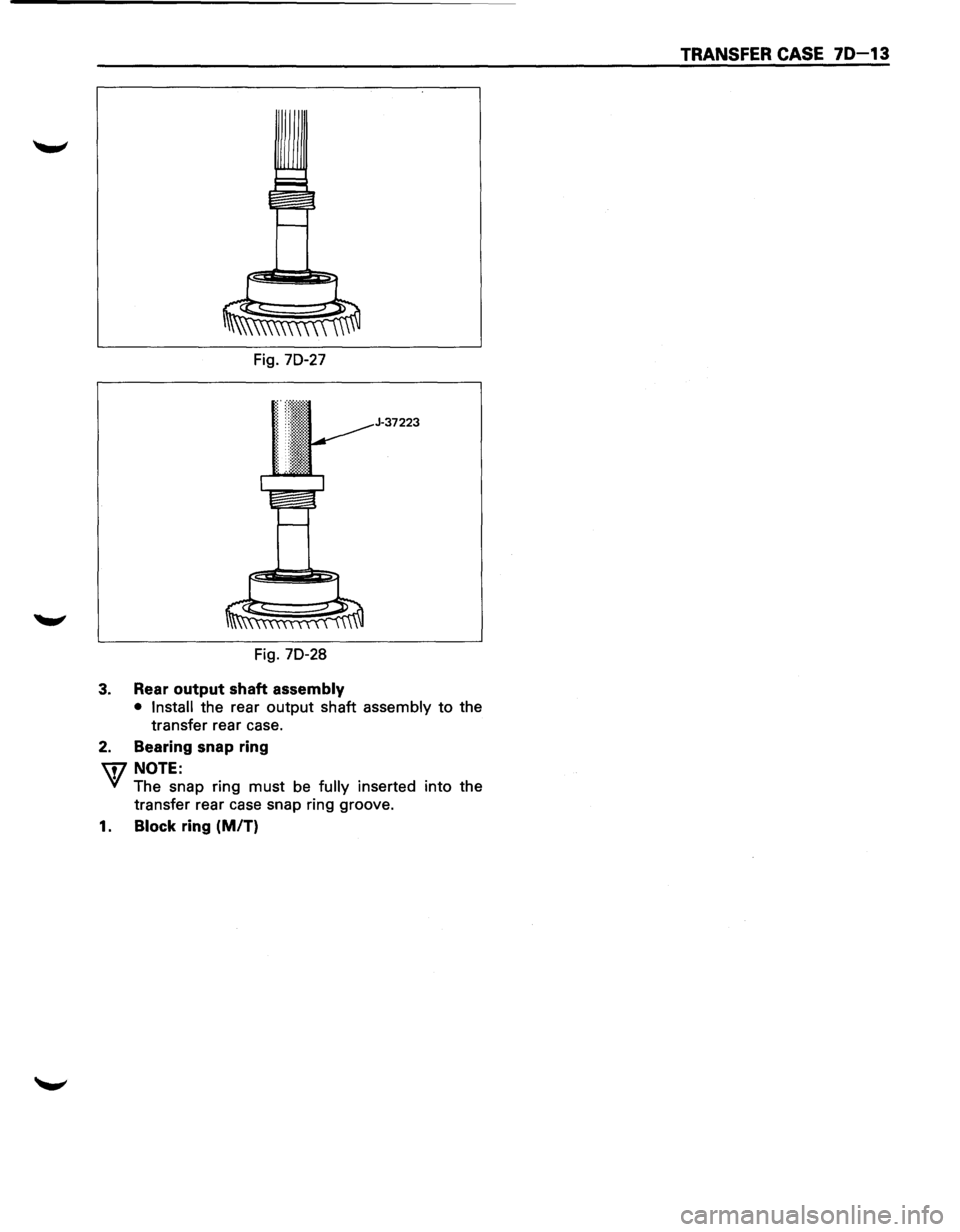
Fig. 70-27
J-37223
Fig. 70-28
3. Rear output shaft assembly
• Install the rear output shaft assembly to the
transfer rear case.
2. Bearing snap ring
'U7 NOTE:
VI The snap ring must be fully inserted into the
transfer rear case snap ring groove.
1. Block ring (MIT)
TRANSFER CASE 70-13
Page 1172 of 1928
70-14 TRANSFER CASE
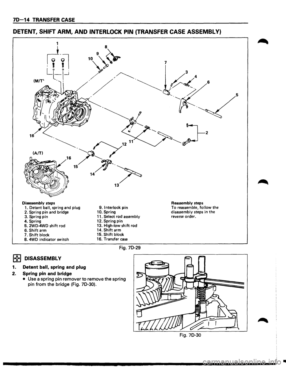
DETENT, SHIFT ARM, AND INTERLOCK PIN (TRANSFER CASE ASSEMBLY)
(A/T)
~. ('71211
16 / ........... -
15 ~·----~ 14 ~ • ~
13
Disassembly steps
1. Detant
ball, spring and plug 9. Interlock pin
2. Spring pin and bridge 10. Spring
3. Spring pin 11. Select rod assembly
4. Spring 12. Spring pin
5.
2WD-4WD shift rod 13. High-low shift
rod
6.
Shift arm 14. Shift arm
7.
Shift block 15. Shift block
8. 4WD indicator switch 16.
Transfer case
Fig. 70-29
1-! .. j DISASSEMBL V
1. Detent ball, spring and plug
2. Spring pin and bridge
• Use a spring pin remover to remove the spring
pin from the bridge (Fig.
70-30).
7
Reassembly steps
To reassemble, follow the disassembly steps in the reverse order.
Fig. 70-30
•
Page 1173 of 1928
3. Spring pin
4. Spring
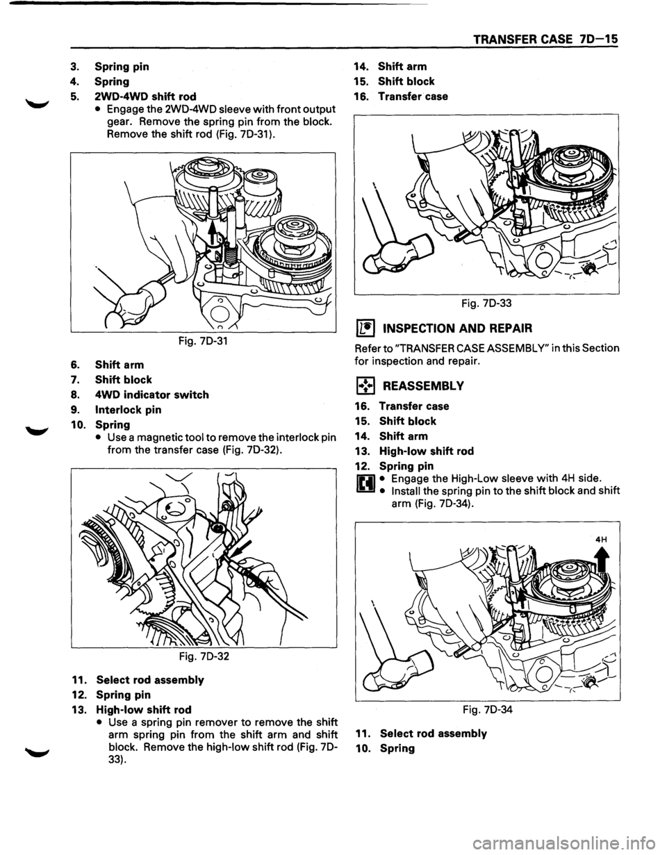
5. 2WD-4WD shift rod
• Engage the 2W0-4WO sleeve with front output
gear. Remove the spring pin from the
block.
Remove the shift rod (Fig. 70-31 ).
Fig. 70-31
6. Shift arm
7. Shift block
8. 4WD indicator switch
9. Interlock pin
10. Spring
• Use a magnetic tool to remove the interlock pin
from the transfer case (Fig.
70-32).
Fig. 70-32
11. Select rod assembly
12.
Spring pin
13. High-low shift rod
• Use a spring pin remover to remove the shift
arm spring pin from the shift arm and shift
block. Remove the high-low shift rod (Fig. 70-
33).
TRANSFER CASE 70-15
14. Shift arm
15.
Shift block
16. Transfer case
Fig. 70-33
11!) INSPECTION AND REPAIR
Refer to "TRANSFER CASE ASSEMBLY" in this Section
for inspection and repair.
1 .. !•1 REASSEMBL V
16. Transfer case
15.
Shift block
14. Shift arm
13.
High-low shift rod
12.
Spring pin
0 • Engage the High-Low sleeve with 4H side.
U • Install the spring pin to the shift block and shift
arm (Fig.
70-34).
Fig. 70-34
11. Select rod assembly
10. Spring
Page 1174 of 1928
70-16 TRANSFER CASE
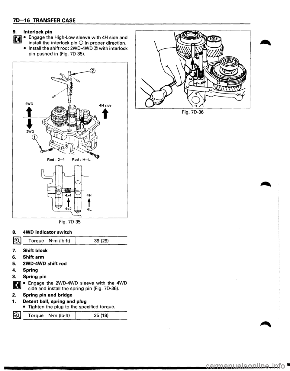
9. Interlock pin
r.:il • Engage the High-Low sleeve with 4H side and
U install the interlock pin CD in proper direction.
• Install the shift rod: 2W0-4WO ®with interlock
pin pushed in (Fig. 70-35).
Fig. 70-35
8. 4WD indicator switch
~~~ Torque N·m (lb·ft)
7. Shift block
6. Shift arm
5. 2WD-4WD shift rod
4. Spring
3. Spring pin
4H side
t
39 (29)
flil1 • Engage the 2W0-4WO sleeve with the 4WD
U side and install the spring pin (Fig. 70-36).
2. Spring pin and bridge
1. Detent ball, spring and plug
• Tighten the plug to the specified torque.
~~~ Torque N·m (lb·ft) I 25 (18)
Fig. 70-36
•
Page 1175 of 1928
TRANSFER CASE ASSEMBL V
39 (AfT)
39
(MIT)
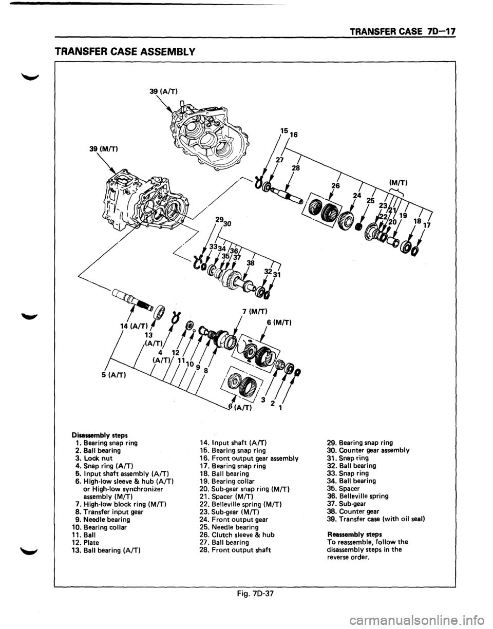
Disassembly steps
1. Bearing snap ring
2.
Sail bearing 3. Lock nut 4. Snap ring (AIT) 5. Input shaft assembly (AIT) 6. High-low sleeve & hub (AIT) or High-low synchronizer
assembly (MIT) 7. High-low block ring (MIT) 8. Transfer input gear
9. Needle bearing
10. Bearing collar 11. Ball
12. Plate
13. Ball bearing
(AIT)
14. Input shaft (A/T)
15. Bearing snap ring
16.
Front output gear assembly
17. Bearing snap ring
18.
Ball bearing
19. Bearing collar
20. Sub-gear snap ring (MIT) 21. Spacer (M/T)
22. Belleville spring (MIT) 23. Sub-gear (MIT) 24. Front output gear
25. Needle bearing
26.
Clutch sleeve & hub 27. Ball bearing
28. Front output shaft
Fig. 70-37
TRANSFER CASE 7D-17
29. Bearing snap ring 30. Counter gear assembly
31.
Snap ring 32. Ball bearing 33. Snap ring
34. Ball bearing
35. Spacer 36. Belleville spring
37. Sub-gear
38. Counter gear 39. Transfer case (with oil seal)
Reassembly steps
To reassemble,
follow the disassembly steps in the reverse order.
Page 1176 of 1928
70-18 TRANSFER CASE
l•!•l DISASSEMBLY
1. Bearing snap ring
• Use a pair of snap ring pliers to remove the
snap ring.
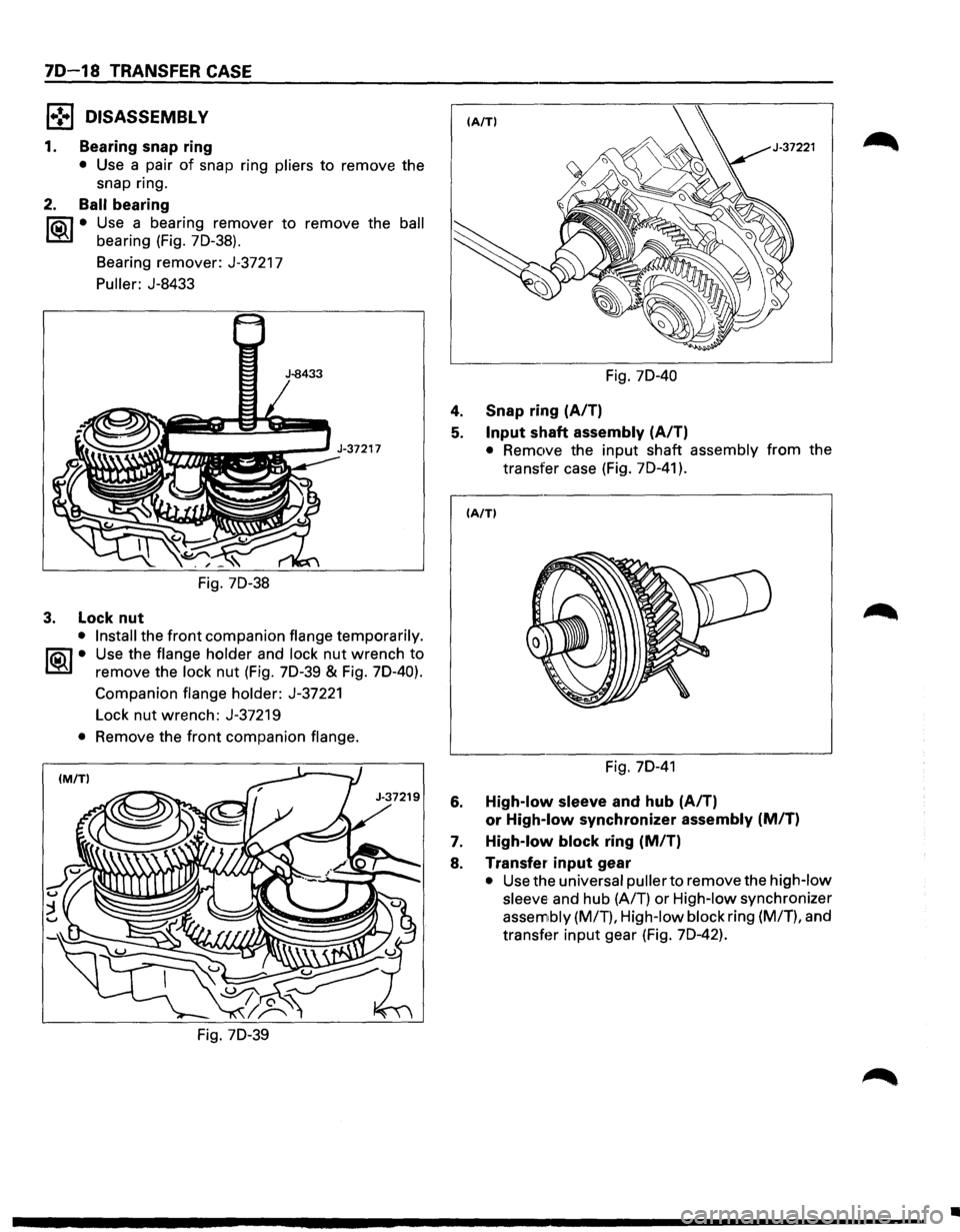
2. Ball bearing
lia\1 • Use a bearing remover to remove the ball
~ bearing (Fig. 7D-38).
Bearing remover: J-37217
Puller: J-8433
Fig. 7D-38
3. Lock nut
• Install the front companion flange temporarily.
I®J • Use the flange holder and lock nut wrench to
remove the lock nut (Fig. 7D-39 & Fig. 70-40).
Companion
flange holder: J-37221
Lock
nut wrench: J-37219
• Remove the front companion flange.
Fig. 7D-39 Fig.
70-40
4. Snap ring
(A/T)
5. Input shaft assembly (A/T)
• Remove the input shaft assembly from the
transfer case (Fig.
7D-41 ).
IA/TI
Fig. 70-41
6. High-low sleeve and hub (A/T)
or
High-low synchronizer assembly (M/T)
7. High-low block ring (M/T)
8. Transfer input gear
• Use the universal puller to remove the high-low
sleeve
and hub (A/T) or High-low synchronizer
assembly (MIT), High-low block ring (M/T), and
transfer input gear (Fig. 7D-42).
•
Page 1180 of 1928
7D-22 TRANSFER CASE
Inspect the components for the following:
• Teeth for wear, scuffs, nicks, burrs or breaks.
• Keys and springs for wear, cracks or distortion,
replace
if these conditions are present.
• If scuffed, 'nicked or burred conditions cannot be
corrected with a soft stone or crocus cloth,
replace the component.
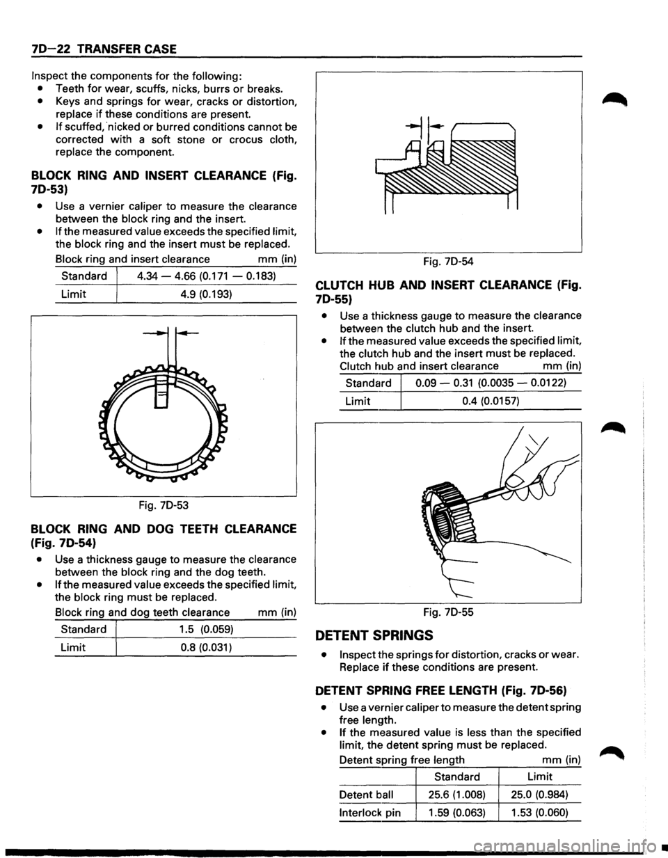
BLOCK RING AND INSERT CLEARANCE (Fig.
7D-53)
• Use a vernier caliper to measure the clearance
between the block ring and the insert.
• If the measured value exceeds the specified limit,
the block ring and the insert
must be replaced.
Block ring and insert clearance
mm (in)
Standard
4.34-4.66 (0.171 - 0.183)
Limit 4.9 (0.193)
Fig. 7D-53
BLOCK RING AND DOG TEETH CLEARANCE
(Fig. 7D-54)
• Use a thickness gauge to measure the clearance
between the block ring and the dog teeth.
• If the measured value exceeds the specified limit,
the block ring
must be replaced. Fig.
7D-54
CLUTCH HUB AND INSERT CLEARANCE (Fig.
7D-55)
• Use a thickness gauge to measure the clearance
between the clutch hub and the insert.
• If the measured value exceeds the specified limit,
the
clutch hub and the insert must be replaced.
Clutch hub and insert clearance
mm (in)
Standard 0.09 -
0.31 (0.0035 -0.0122)
Limit 0.4 (0.0157)
Block ring and dog teeth clearance
mm (in) Fig. 7D-55 ------~~--~------------------~ Standard 1.5 (0.059)
Limit 0.8
(0.031) DETENT SPRINGS
• Inspect the springs for distortion, cracks or wear.
Replace
if these conditions are present.
DETENT SPRING FREE LENGTH (Fig. 7D-56)
• Use a vernier caliper to measure the detent spring
free length.
• If the measured value is less than the specified
limit, the detent spring
must be replaced.
Detent spring free length
mm (in)
Standard Limit
Detent ball 25.6
(1.008) 25.0 (0.984)
Interlock pin 1.59 (0.063) 1.53
(0.060)
•
Page 1181 of 1928
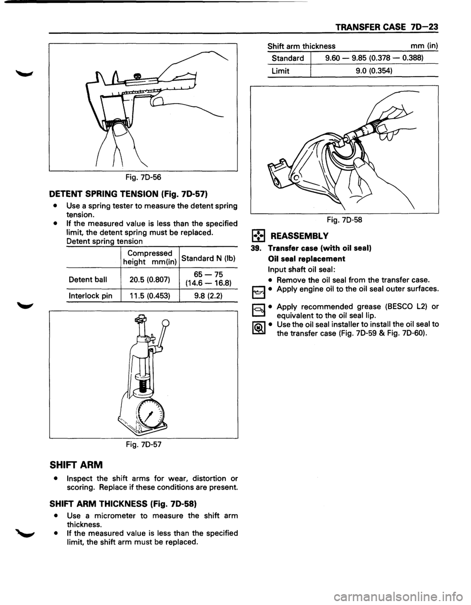
Fig. 7D-56
DETENT SPRING TENSION (Fig. 70-57)
• Use a spring tester to measure the detent spring
tension.
• If the measured value is less than the specified
limit, the detent spring must be replaced.
Detent spring tension
Compressed Standard N (lb)
height mm(in)
Detent
ball 20.5 (0.807) 65-75
(14.6 -16.8)
Interlock pin 11.5 (0.453) 9.8 (2.2)
Fig. 7D-57
SHIFT ARM
•
Inspect the shift arms for wear, distortion or
scoring. Replace
if these conditions are present.
SHIFT ARM THICKNESS (Fig. 70-58)
• Use a micrometer to measure the shift arm
thickness.
• If the measured value is less than the specified
limit, the shift arm must be replaced.
TRANSFER CASE 70-23
Shift arm thickness mm (in)
Standard
9.60 - 9.85 (0.378 -0.388)
Limit 9.0 (0.354)
Fig. 7D-58
l•!•l REASSEMBL V
39. Transfer case (with oil seal)
Oil
seal replacement
Input shaft oil seal:
• Remove the oil seal from the transfer case.
j3 • Apply engine oil to the oil seal outer surfaces.
r.:;::'l • Apply recommended grease (BESCO L2) or
D equivalent to the oil seal lip.
li:\1 • Use the oil seal installer to install the oil seal to
~ the transfer case (Fig. 7D-59 & Fig. 7D-60).