lock ISUZU TROOPER 1995 Workshop Manual
[x] Cancel search | Manufacturer: ISUZU, Model Year: 1995, Model line: TROOPER, Model: ISUZU TROOPER 1995Pages: 1928
Page 1127 of 1928
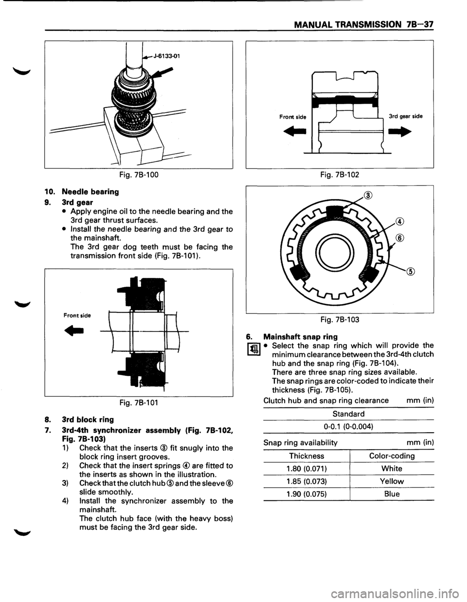
MANUAL TRANSMISSION 78-37
Fig. 78-100 Fig. 78-102
10. Needle bearing
9. 3rd gear
• Apply engine oil to the needle bearing and the
3rd gear
thrust surfaces.
• Install the needle bearing and the 3rd gear to
the mainshaft.
The 3rd gear dog teeth
must be facing the
transmission
front side (Fig. 78-101 ).
Front side
..
Fig. 78-101
8. 3rd block ring
7. 3rd-4th synchronizer assembly (Fig. 78-102,
Fig. 78·103)
1) Check that the inserts @ fit snugly into the
block ring insert grooves.
2) Check that the insert springs @ are fitted to
the inserts as shown in the illustration.
3) Check that the clutch hub@and the sleeve®
slide smoothly.
4) Install the synchronizer assembly to the
mainshaft.
The
clutch hub face (with the heavy boss)
must be facing the 3rd gear side. Fig.
78-103
6. Mainshaft snap ring
l"fil • Select the snap ring which will provide the
l..!l!l minimum clearance between the 3rd-4th clutch
hub and the snap ring (Fig. 78-1 04).
There are three snap ring sizes available.
The snap rings are color-coded to indicate their
thickness (Fig.
78-1 05).
Clutch
hub and snap ring clearance mm (in)
Standard
0-0.1 (0-0.004)
Snap
ring availability mm (in)
Thickness
Color-coding
1.80 (0.071)
White
1.85
(0.073) Yellow
1.90 (0.075) Blue
Page 1128 of 1928
78-38 MANUAL TRANSMISSION
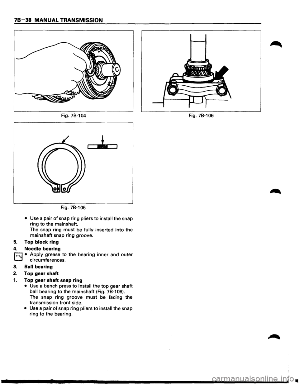
Fig. 78-104
Fig. 78-105
• Use a pair of snap ring pliers to install the snap
ring to the mainshaft.
The snap ring
must be fully inserted into the
mainshaft snap ring groove.
5. Top block ring
4. Needle bearing
r::J • Apply grease to the bearing inner and outer
D circumferences.
3. Ball bearing
2. Top gear shaft
1. Top gear shaft snap ring
• Use a bench press to install the top gear shaft
ball bearing to the mainshaft (Fig. 78-106).
The snap ring groove
must be facing the
transmission
front side.
• Use a pair of snap ring pliers to install the snap
ring
to the bearing. Fig.
78-106
•
Page 1135 of 1928
CLUTCH 7C-1
SECTION 7C
CLUTCH
W CAUTION:
• When fasteners are removed, always reinstall them at the same location from which they were removed. If a
fastener needs to be
replaced, use the correct part number fastener for that application. If the correct part
number fastener is
not available, a fastener of equal size and strength (or stronger) may be used. Fasteners
that are not reused, and those requiring thread locking compound, will be called out. The correct torque
values must be used when installing fasteners that require torque. If the above conditions are not followed,
parts or system damage could result.
CONTENTS
General Description .................. 7C-2
Clutch ............................ 7C-2
Master
Cylinder ................... 7C- 3
Damper
Cylinder ................... 7C- 3
Slave Cylinder ..................... 7C-3
Pressure
Plate Assembly ........... 7C-4
Driven
Plate Assembly ............. 7C-4
Diagnosis
............................ 7C- 5
On-Vehicle Service ................... 7C-6
Clutch Assembly . .
. . . . . . . . . . . . . . . .
7C-6
Clutch Control . .
. . . . . . . . . . . . . . . . . .
7C-13
Master
Cylinder . .
. . . . . . . . . . . . . . . . .
7C-17
Slave Cylinder . .
. . . . . . . . . . . . . . . . . .
7C-18
Damper
Cylinder . .
. . . . . . . . . . . . . . . .
7C-20
Main
Data And Specifications . .
. . . . . .
7C-21
General Specifications
. . . . . . . . . . . . . 7C-21
Torque Specifications ............. 7C-22
Special Tools ........................ 7C-24
Page 1139 of 1928
CLUTCH 7C-5
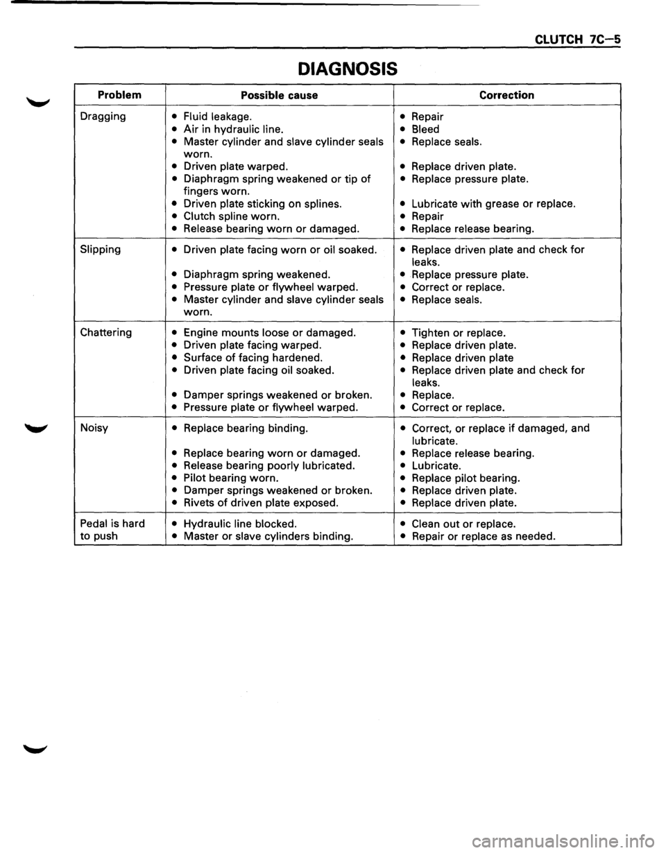
DIAGNOSIS
Problem Possible cause Correction
Dragging • Fluid leakage.
• Repair
• Air in hydraulic line.
• Bleed
•
Master cylinder and slave cylinder seals • Replace seals.
worn.
• Driven plate warped. • Replace driven plate.
•
Diaphragm spring weakened or tip of • Replace pressure plate.
fingers worn.
• Driven plate sticking on splines. • Lubricate with grease or replace.
• Clutch spline
worn. • Repair
• Release bearing worn or damaged. • Replace release bearing.
Slipping
• Driven plate facing worn or oil soaked. • Replace driven plate and check for
leaks.
•
Diaphragm spring weakened. • Replace pressure plate.
•
Pressure plate or flywheel warped. • Correct or replace.
•
Master cylinder and slave cylinder seals
• Replace seals.
worn.
Chattering
• Engine mounts loose or damaged. • Tighten or replace.
•
Driven plate facing warped. • Replace driven plate.
•
Surface of facing hardened. • Replace driven plate
•
Driven plate facing oil soaked. • Replace driven plate and check for
leaks.
•
Damper springs weakened or broken. • Replace.
•
Pressure plate or flywheel warped. • Correct or replace.
Noisy • Replace bearing binding. • Correct, or replace if damaged, and
lubricate.
• Replace
bearing worn or damaged. • Replace release bearing.
• Release bearing poorly lubricated.
• Lubricate.
• Pilot bearing worn. • Replace pilot bearing.
• Damper springs weakened or broken. • Replace driven plate.
•
Rivets of driven plate exposed. • Replace driven plate.
Pedal
is hard • Hydraulic line blocked.
• Clean out or replace.
to push • Master or slave cylinders binding. • Repair or replace as needed.
Page 1143 of 1928
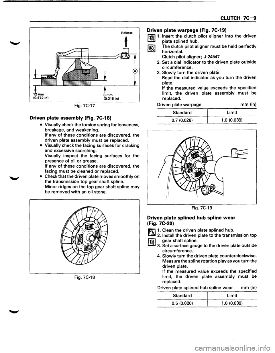
Fig. 7C-17
mm (0.315 in)
Driven plate assembly (Fig. 7C-18)
Release
t
• Visually check the torsion spring for looseness,
breakage, and weakening.
If any of these conditions are discovered, the
driven
plate assembly must be replaced.
• Visually check the facing surfaces for cracking
and excessive scorching.
Visually inspect the facing surfaces for the
presence
of oil or grease.
If any of these conditions are discovered, the
facing
must be cleaned or replaced.
• Check that the driven plate moves smoothly on
the transmission
top gear shaft spline.
Minor ridges on the top gear shaft spline may
be removed
with an oil stone.
Fig. 7C-18
CLUTCH 7C-9
Driven plate warpage (Fig. 7C-19)
l'fil1. Insert the clutch pilot aligner into the driven
1.!!!1 plate splined hub.
li5\l The clutch pilot aligner must be held perfectly
I.::2Y horizontal.
Clutch pilot
aligner; J-24547
2. Set a dial indicator to the driven plate outside
circumference.
3. Slowly turn the driven plate.
Read the dial indicator as you turn the driven
plate.
If
the measured value exceeds the specified
limit, the driven plate assembly must be
replaced.
Driven
plate warpage mm (in)
Standard Limit
0.7 (0.028) 1.0
(0.039)
Fig. 7C-19
Driven plate splined hub spline wear
(Fig.
7C-20)
E1 1. Clean the driven plate splined hub.
l...al 2. Install the driven plate to the transmission top
ffi1 gear shaft spline.
1.!!1 3. Set a surface gauge to the driven plate outside
circumference.
4. Slowly turn the driven plate counterclockwise.
Measure the
spline rotation play as you turn the
driven
plate.
If
the measured value exceeds the specified
limit, the driven plate assembly must be
replaced.
Driven
plate splined hub spline wear mm (in)
Standard Limit
0.5 (0.020) 1.0 (0.039)
Page 1145 of 1928
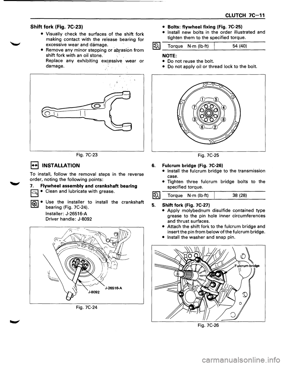
Shift fork (Fig. 7C-23)
• Visually check the surfaces of the shift fork
making contact
with the release bearing for
excessive wear and damage.
• Remove any minor stepping or ah,rasion from
shift fork with an oil stone.
Replace any exhibiting
· ex«?~ssive wear or
damage.
Fig.
7C-23
1••1 INSTALLATION
To install, follow the removal steps in the reverse
order, noting the
following points:
7. Flywheel assembly and crankshaft bearing
§I• Clean and lubricate with grease.
1®..1• Use the installer to install the crankshaft
bearing (Fig. 7C-24).
Installer: J-26516-A
Driver handle: J-8092
Fig.
7C-24
CLUTCH 7C-11
• Bolts: flywheel fixing (Fig. 7C-25)
• Install new bolts in the order illustrated and
tighten them to the specified torque.
1~1 Torque N·m (lb·ft) I 54 (40)
6.
NOTE:
• Do not reuse the bolt.
•
Do not apply oil or thread lock to the bolt.
Fig. 7C-25
Fulcrum bridge (Fig. 7C-26)
• Install the fulcrum bridge to the transmission
case.
• Tighten three fulcrum bridge bolts to the
specified torque.
I~I __ T_o_rq~u_e __ N_·_m~(_lb_·ft_l~ _____ 3_8_(_28_) ____ _
5. Shift fork (Fig. 7C-27)
• Apply molybednum disulfide contained type
grease
to the pin hole inner circumferences
and thrust surfaces.
• Attach the shift fork to the fulcrum bridge and
insert the pin
from below of the fulcrum bridge.
• Install the washer and snap pin.
Fig.
7C-26
Page 1148 of 1928
7C 14 CLUTCH
1••1 REMOVAL
1. Pin and jaw joint pin
2. Pedal assembly and switch
3. Oil line pipe
4. Slave cylinder assembly and heat protector
5. Master cylinder assembly
6. Damper cylinder assembly
ll.•l INSPECTION AND REPAIR
Make necessary adjustments, repairs, and part
replacement
if wear, damage or other problems are
discovered during inspection.
1••1 INSTALLATION
To install, follow the removal steps in the reverse
order, noting the
following points:
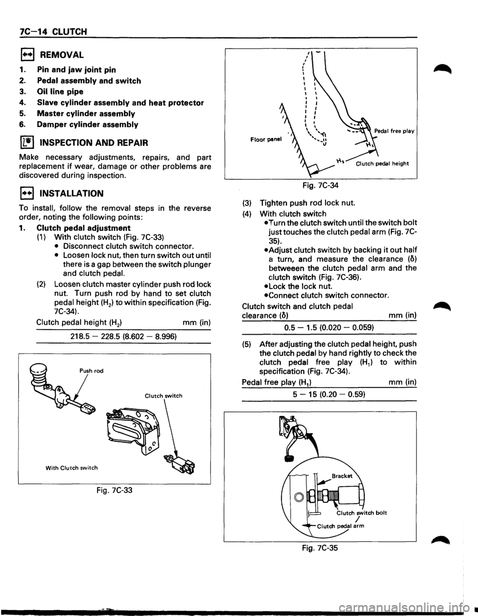
1. Clutch pedal adjustment
(1) With clutch switch (Fig. 7C-33)
• Disconnect clutch switch connector.
• Loosen lock nut, then turn switch out until
there is a gap between the switch plunger
and
clutch pedal.
(2) Loosen clutch master cylinder push rod lock
nut. Turn push rod by hand to set clutch
pedal height (H2) to
within specification (Fig.
7C-34).
Clutch
pedal height (H2 ) mm (in)
218.5
-228.5 (8.602 -8.996)
Clutch switch
With Clutch switch
Fig. 7C-33
Floor panel
Fig. 7C-34
(3) Tighten push rod lock nut.
(4) With clutch switch
Clutch pedal height
•Turn the clutch switch until the switch bolt
justtouches the clutch pedal arm (Fig. 7C
:~5).
•Adjust clutch switch by backing it out half
a
turn, and measure the clearance (o)
betweeen the clutch pedal arm and the
c:lutch switch (Fig. 7C-36).
•Lock the lock nut.
•Connect clutch switch connector.
Clutch switch and clutch
pedal
clearance
(o) mm (in)
0.5 -1.5 (0.020 -0.059)
(5) After adjusting the clutch pedal height, push
the clutch pedal
by hand rightly to check the
clutch pedal free play (H1) to within
specification (Fig. 7C-34).
Pedal free play (H1) mm (in)
5 -
15 (0.20 -0.59)
Fig. 7C-35
•
Page 1149 of 1928
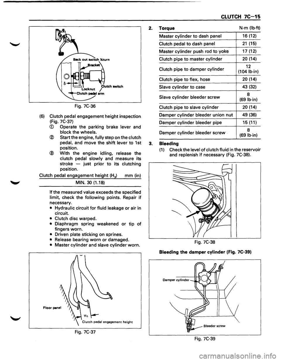
Fig. 7C-36
(6) Clutch pedal engagement height inspection
(Fig.
7C-37)
® Start the engine, fully step on the clutch
pedal,
and move the shift lever to 1st
position.
@ With the engine idling, release the
clutch pedal slowly and measure its
stroke -just prior
to its clutching
position.
Clutch pedal engagement height (H3) mm (in)
MIN. 30 (1.18)
If the
measured value exceeds the specified
limit, check the following points. Repair if
necessary.
• Hydraulic circuit for fluid leakage or air in
circuit.
• Clutch disc warped.
• Diaphragm spring weakened or tip of
fingers worn.
• Driven plate sticking on sprines.
• Release bearing worn or damaged.
• Master cylinder and slave cylinder worn.
Floor panel
Fig. 7C-37
CLUTCH 7C-15
2. Torque N·m (lb·ft)
Master cylinder to dash panel 16 (12)
Clutch pedal to dash panel 21 (15)
Master cylinder push rod to yoke 17 (12)
Clutch pipe to master cylinder 20 (14)
Clutch pipe
to damper cylinder 12
(104 lb·in)
Clutch
pipe to flex, hose 20 (14)
Slave cylinder to case 43 (32)
Slave
cylinder bleeder screw 8 (691b·in)
Clutch
pipe to slave cylinder 20 (14)
Damper cylinder bleeder union nut 49 (36)
Damper cylinder bleeder pipe 15 (11)
Damper cylinder
bleeder screw 8 (69 lb·in)
3. Bleeding
(1) Check
the level of clutch fluid in the reservoir
and
replenish if necessary (Fig. 7C-38).
Fig. 7C-38
Bleeding the damper cylinder (Fig. 7C-39)
Damper cylinder
Fig. 7C-39
Page 1159 of 1928
TRANSFER CASE 7D-1
SECTION 70
TRANSFER CASE
w CAUTION:
When fasteners are removed, always reinstall them at the same location from which they were removed. If a
fastener needs
to be replaced, use the correct part number fastener for that application. If the correct part
number is not available, a fastener
of equal size and strength (or stronger) may be used. Fasteners that are
not reused, and those requiring thread locking compound, will
be called out. The correct torque values must
be used when installing fasteners that require torque.
If the above conditions are not followed, parts or
system damage could result.
CONTENTS
General Description ................... 7D-1
Construction . . . . . . . . . . . . . . . . . . . . . . . . . 7D-2
On-Vehicle Service .................... 7D-3
Transfer
Case (A/T) .................. 7D-3
Transfer Rear
Oil Seal ................ 7D-5
Unit Repair ........................... 7D-8
Transfer
Case Assembly (AfT) ........ 7D-8
Transfer Rear
Case Assembly . .
. . . . . 7D-11
Detent, Shift Arm, And
Interlock Pin (Transfer
Case Assembly) . .
. . . . . . . . . . . . . . . . . . 7D-14 Transfer
Case
Assembly . .
. . . . . . . . . .
7D-17
Main Data And Specifications . . . . . . . .
70-29
General
Specifications . .
. . . . . . . . . . . .
70-29
Torque
Specifications ............... 7D-30
Special Tools
........................ 7D-32
GENERAL DESCRIPTION
The transfer case is used to provide a means of
providing power flow to the front axle. The transfer
case also provides a means of disconnecting the front
axle, providing better fuel economy and quieter
operation when the vehicle is driven
on improved
roads where four wheel drive is not required.
In
addition, the transfer case provides an additional gear
reduction when placed in low range, which
is useful
when difficult off-road conditions are encountered. A
floor mounted shift lever is used to select the
operating range. When four wheel drive has been
selected, the four wheel drive indicator light is
designed to come
on when the front axle has been
engaged.
Page 1161 of 1928
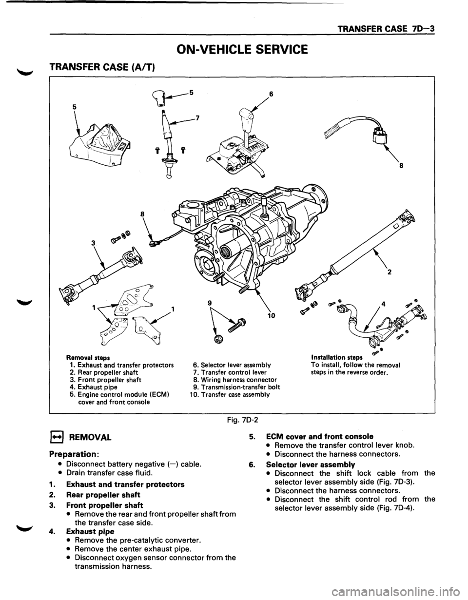
TRANSFER CASE 70-3
ON-VEHICLE SERVICE
TRANSFER CASE (A/T)
5
<;J---5 6
7
' 8
9
~
10
Removal steps Installation steps
1. Exhaust and transfer protectors 6. Selector lever
assembly To
install, follow the removal
steps in the reverse order.
2. Rear propeller shaft 7.
Transfer control lever
3. Front propeller shaft 8.
Wiring harness connector
4. Exhaust pipe 9. Transmission-transfer bolt
5. Engine control module
(ECM)
cover and front console 10.
Transfer case assembly
Fig. 7D-2
l••l REMOVAL
Preparation:
• Disconnect battery negative (-) cable.
•
Drain transfer case fluid.
1. Exhaust and transfer protectors
2. Rear propeller shaft
3. Front propeller shaft
• Remove the rear and front propeller shaft from
the transfer case side.
4. Exhaust pipe
• Remove the pre-catalytic converter.
• Remove the center exhaust pipe.
• Disconnect oxygen sensor connector from the
transmission harness.
5. ECM cover and front console
• Remove the transfer control lever knob.
• Disconnect the harness connectors.
6. Selector lever assembly
• Disconnect the shift lock cable from the
selector lever assembly side (Fig. 7D-3).
• Disconnect the harness connectors.
• Disconnect the shift control rod from the
selector lever assembly side (Fig. 7D-4).