lock ISUZU TROOPER 1995 Workshop Manual
[x] Cancel search | Manufacturer: ISUZU, Model Year: 1995, Model line: TROOPER, Model: ISUZU TROOPER 1995Pages: 1928
Page 1090 of 1928
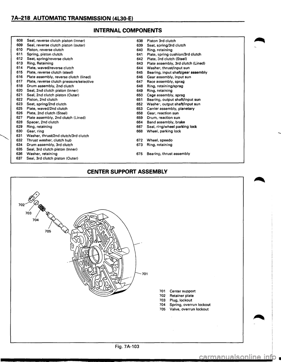
7A-218 AUTOMATIC TRANSMISSION (4L30-E}
608 Seal, reverse clutch piston (inner)
609 Seal, reverse clutch piston (outer)
610 Piston, reverse clutch 611 Spring, piston clutch 612 Seat, spring/reverse clutch 613 Ring, Retaining
614
Plate, waved/reverse clutch 615 Plate, reverse clutch (steel) 616 Plate assembly, reverse clutch (lined)
617 Plate, reverse clutch pressure/selective
618 Drum assembly, 2nd clutch
620 Seal, 2nd clutch piston (Inner) 621 Seal, 2nd clutch piston (Outer) 622 Piston, 2nd clutch
623 Seat, spring/2nd clutch 625 Plate, waved/2nd clutch 626 Plate, 2nd clutch (Steel)
627 Plate assembly, 2nd clutch (Lined)
628 Spacer, 2nd clutch 629 Ring, retaining
630 Gear, ring 631 Washer, thrust/2nd clutch/3rd clutch 632 Thrust washer, clutch hub
634 Drum assembly, 3rd clutch
635 Seal, 3rd clutch piston (Inner) 636 Washer, retaining
637 Seal, 3rd clutch piston (Outer)
INTERNAL COMPONENTS
638 Piston 3rd clutch 639 Seat, spring/3rd clutch
640 Ring, n~taining 641 Plate, spring cushion/3rd clutch 642 Plate, :::rd clutch (Steel) 643 Plate assembly, 3rd clutch (Lined)
644 Washer,
thrust/input sun
645 Bearino, input shaft/gear assembly 646 Gear assembly, input sun
647
Race assembly, sprag
648 Ring, mtaining/sprag
649 Ring,
mtaining 650 Cage a:;sembly, sprag 651 Bearinn, output shaft/input sun
652 Washer, output shaft/input sun
653 Carrier assembly, planetary 658 Gear, reaction sun
659 Drum, 1·eaction sun
664 Band
assembly, brake 667 Seal, ring/wheel parking lock 668 Wheel, parking lock
672 Wheel, speedo
673 Ring, rEttaining
675
Bearin~1. thrust assembly
CENTER SUPPORT ASSEMBLY
701
Fig. 7A-103
701 Center support 702 Retainer plate
703 Plug, lockout
704 Spring,
overrun lockout
705 Valve,
overrun lockout
•
Page 1091 of 1928
MANUAL TRANSMISSION 78-1
SECTION 78
MANUAL TRANSMISSION
w CAUTION
When fasteners are removed, always reinstall them at the same location from which they were removed. If a
fastener needs
to be replaced, use the correct part number fastener for that application. If the correct part
number fastener is not available, a fastener of equal size and strength (or stronger) may be used. Fasteners
that are not reused, and those requiring thread locking compound, will be called out. The correct torque
values must be used when installing fasteners that require torque. If the above conditions are not followed,
parts or system damage could result.
CONTENTS
General Description . . . . . . . . . . . . . . . . . . . . . 78-1
Construction . . . . . . . . . . . . . . . . . . . . . . . . . 78-2
Diagnosis . . . . . . . . . . . . . . . . . . . . . . . . . . . . . . 78-3
On-Vehicle Service ..................... 78-4
Transmission . . . . . . . . . . . . . . . . . . . . . . . . 78-4
Gear Control Box Assembly . . . . . . . . . . . 78-10
Unit Repair ........................... 78-12
Transmission Case And Transfer
Case .............................. 78-12
Intermediate Plate With Gear Assembly
Detent, Shift Arm, And Interlock Pin ... 78-18
Reverse Gear
And 5th Gear ............ 78-22
Top Gear Shaft, Main Gear Shaft
And Counter Gear Shaft .............. 78-29
Main Data And Specifications ............ 78-39
General Specifications ................ 78-39
Torque Specifications ................ 78-40
Special
Tools .......................... 78-43
GENERAL DESCRIPTION
The MUA5C is a constant mesh transmission,
synchronized in
all speeds. The transmission is
designed
for ease of shifting and the quietest possible
operation.
Principle parts of the transmission are the integral
clutch
housing, intermediate plate, the transfer case,
the rear cover, and the gears.
The transmission
control box and transfer control box
are
built into the transfer case.
Page 1093 of 1928
MANUAL TRANSMISSION 78-3
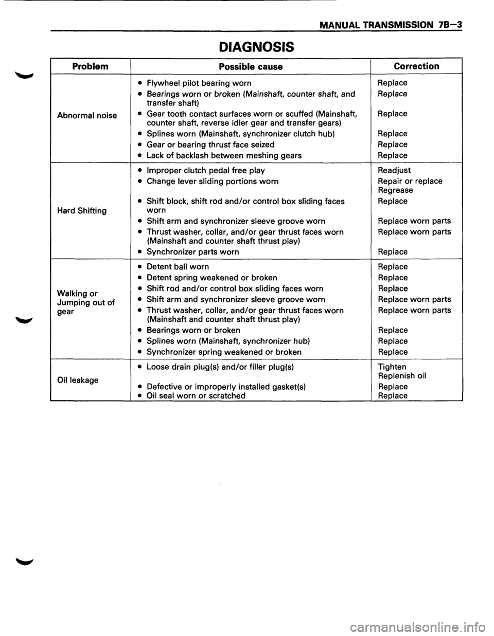
DIAGNOSIS
Problem Possible cause Correction
•
Flywheel pilot bearing worn Replace
•
Bearings worn or broken (Mainshaft, counter shaft, and Replace
transfer shaft)
Abnormal noise • Gear tooth contact surfaces worn or scuffed (Mainshaft, Replace
counter shaft, reverse idler gear and transfer gears)
• Splines worn (Mainshaft, synchronizer clutch hub) Replace
•
Gear or bearing thrust face seized Replace
•
Lack of backlash between meshing gears Replace
• Improper clutch pedal
free play Readjust
• Change lever sliding portions worn Repair or replace
Regrease
• Shift block, shift rod and/or control box sliding faces Replace
Hard Shifting worn
• Shift arm and synchronizer sleeve groove worn Replace worn parts
• Thrust washer, collar, and/or gear thrust faces worn Replace worn parts
(Mainshaft and counter shaft thrust
play)
•
Synchronizer parts worn Replace
•
Detent ball worn Replace
•
Detent spring weakened or broken Replace
Walking
or • Shift rod and/or control box sliding faces worn Replace
Jumping out of • Shift arm and synchronizer sleeve groove worn Replace worn parts
gear
• Thrust washer, collar, and/or gear thrust faces worn Replace worn parts
(Mainshaft and counter shaft thrust
play)
•
Bearings worn or broken Replace
• Splines
worn (Mainshaft, synchronizer hub) Replace
•
Synchronizer spring weakened or broken Replace
•
Loose drain plug(s) and/or filler plug(s) Tighten
Oil leakage Replenish
oil
• Defective or improperly installed gasket(s) Replace
• Oil seal
worn or scratched Replace
Page 1102 of 1928
78-12 MANUAL TRANSMISSION
UNIT REPAIR
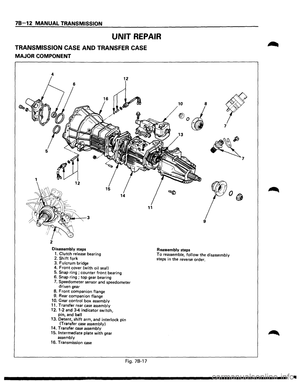
TRANSMISSION CASE AND TRANSFER CASE
MAJOR COMPONENT
4
11
2
Disassembly steps Reassembly steps 7
~
9
1. Clutch release
bearing 2. Shift fork
3. Fulcrum bridge To reassemble, follow the disassembly
steps in the reverse order.
4.
Front cover (with oil seal)
5. Snap ring ; counter front bearing
6. Snap ring ; top gear bearing
7. Speedometer sensor and speedometer
driven gear
8. Front companion flange
9. Rear companion flange
10. Gear control box assembly
11. Transfer rear case assembly
12.
1·2 and 3-4 indicator switch,
pin, and ball 13. Detent, shift arm, and interlock pin
(Transfer case assembly) 14. Transfer case assembly
15. Intermediate plate with gear
assembly
16. Transmission case
Fig. 78-17
7
Ill
Page 1104 of 1928
78-14 MANUAL TRANSMISSION
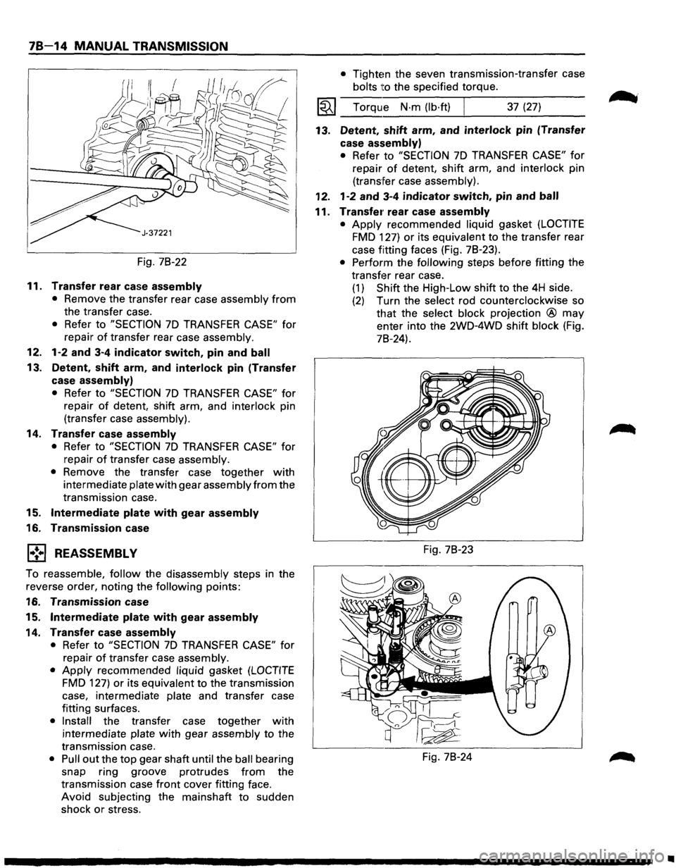
Fig. 78-22
11. Transfer rear case assembly
• Remove the transfer rear case assembly from
the transfer case.
• Refer to "SECTION 7D TRANSFER CASE" for
repair
of transfer rear case assembly.
12. 1-2 and 3-4 indicator switch, pin and ball
13. Detent, shift arm, and interlock pin (Transfer
case
assembly)
• Refer to "SECTION 7D TRANSFER CASE" for
repair of detent, shift arm, and interlock pin
(transfer case assembly).
14. Transfer case assembly
• Refer to "SECTION 7D TRANSFER CASE" for
repair
of transfer case assembly.
• Remove the transfer case together with
intermediate plate with gear assembly from the
transmission case.
15. Intermediate plate with gear assembly
16. Transmission case
l•!•l REASSEMBLY
To reassemble, follow the disassembly steps in the
reverse order, noting the following points:
16. Transmission case
15.
Intermediate plate with gear assembly
14. Transfer case assembly
• Refer to "SECTION 7D TRANSFER CASE" for
repair
of transfer case assembly.
• Apply recommended liquid gasket (LOCTITE
FMD 127) or its equivalent to the transmission
case, intermediate plate and transfer case
fitting surfaces.
• Install the transfer case together with
intermediate plate with gear assembly to the
transmission case.
• Pull out the top gear shaft until the ball bearing
snap ring groove protrudes
from the
transmission case
front cover fitting face.
Avoid subjecting the mainshaft
to sudden
shock
or stress.
• Tightem the seven transmission-transfer case
bolts
ito the specified torque.
I~I __ T_o_rq~u __ e __ N_·_m_(~lb_·f~t)~ ______ 3_7_(2_7~) ____ _
13. Detent, shift arm, and interlock pin (Transfer
case
assembly)
• Refer to "SECTION 7D TRANSFER CASE" for
repair of detent, shift arm, and interlock pin
(transfer case assembly).
12. 1-2 and 3-4 indicator switch, pin and ball
11. Transfe1· rear case assembly
• Apply recommended liquid gasket (LOCTITE
FMD 127) or its equivalent to the transfer rear
case fitting faces (Fig. 78-23).
• Perform the following steps before fitting the
transf13r rear case.
(1) Shift the High-Low shift to the 4H side.
(2) Turn the select rod counterclockwise so
that the select block projection ® may
enter into the 2WD-4WD shift block (Fig.
78-24).
Fig. 78-23
Fig. 78-24
•
Page 1108 of 1928
78-18 MANUAL TRANSMISSION
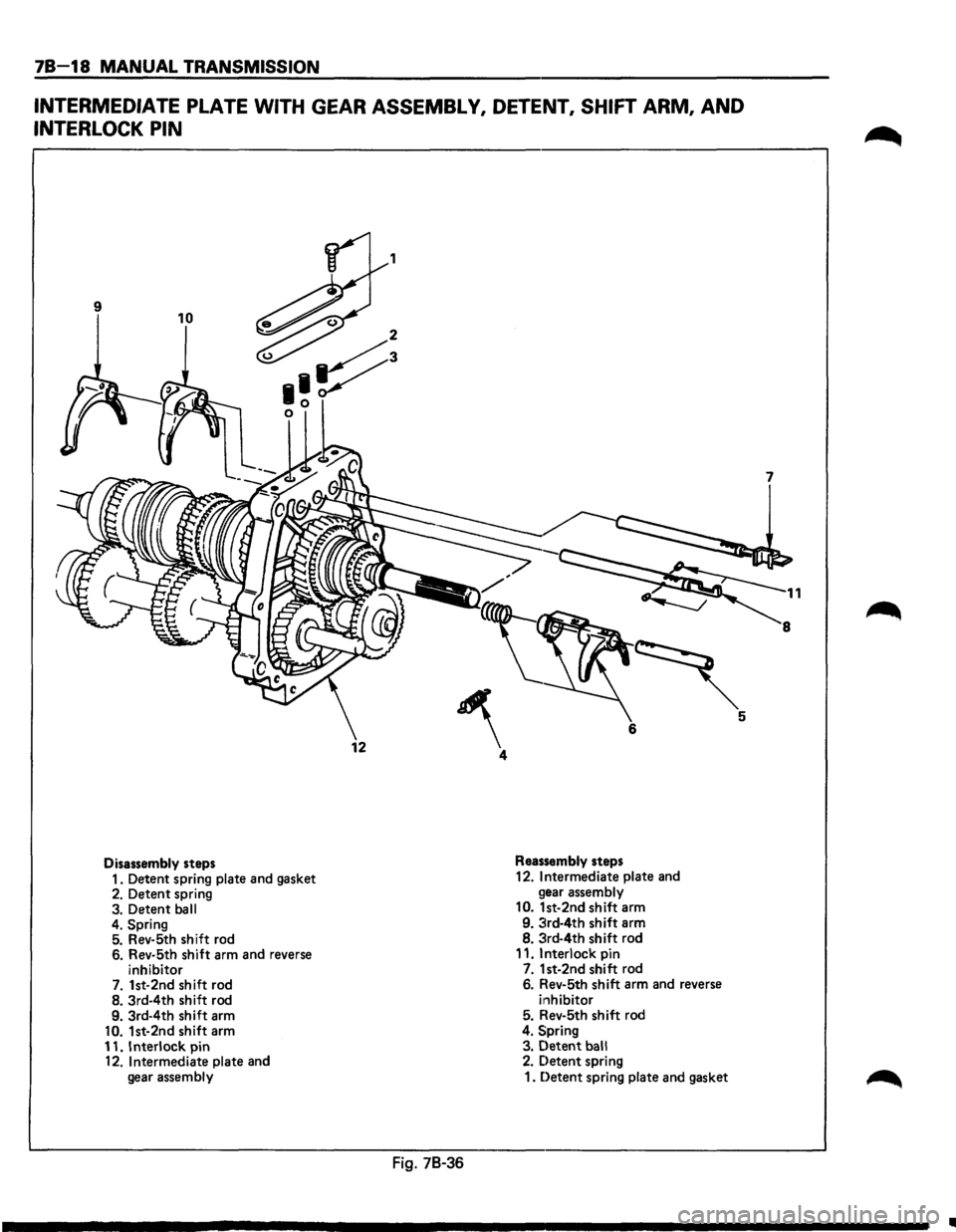
INTERMEDIATE PLATE WITH GEAR ASSEMBLY, DETENT, SHIFT ARM, AND
INTERLOCK PIN
9 10
Disassembly steps
1. Detent spring plate and gasket
2. Detent spring
3. Detent ball
4. Spring 5. Rev-5th shift rod
6. Rev-5th shift arm and reverse
inhibitor
7. 1st-2nd shift rod
8. 3rd-4th shift rod
9. 3rd-4th shift arm
10. 1st-2nd shift arm
11. Interlock pin
12. Intermediate plate and
gear assembly
12
1
~ 4
Fig. 78-36
Reassembly steps
12.
Intermediate plate and
gear assembly
10. 1st-2nd shift arm
9. 3rd-4th shift arm
8. 3rd-4th shift rod
11.
Interlock pin 7. 1st-2nd shift rod 6. Rev-5th shift arm and reverse
i11hibitor 5. Rev-5th shift rod
4. Spring 3. Detent ball 2. Detent spring
1. Detent spring plate and gasket
7
1
•
Page 1109 of 1928
1 .. !•1 DISASSEMBL V
1. Detent spring plate and gasket
2. Detent spring
3. Detent ball
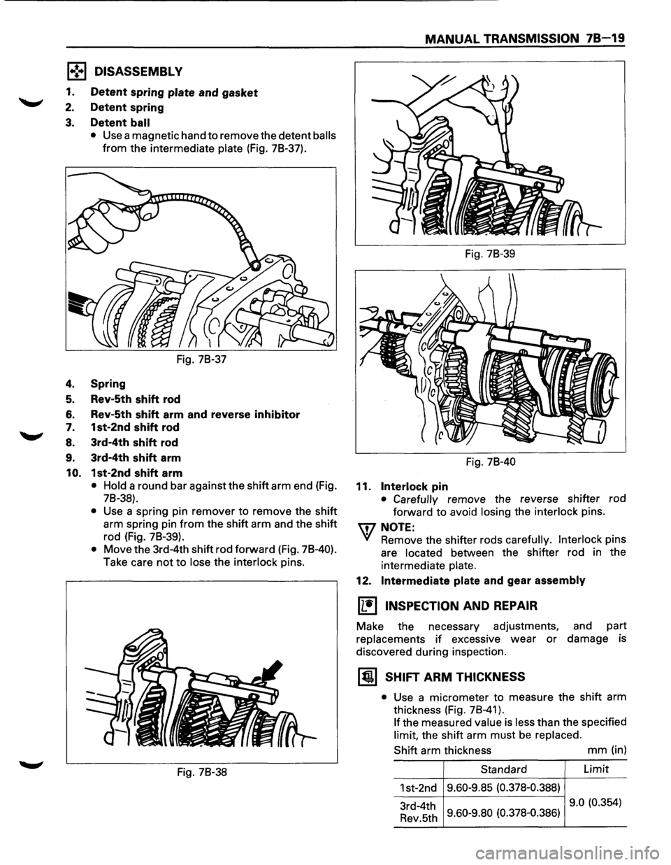
• Use a magnetic hand to remove the detent balls
from the intermediate plate (Fig. 78-37).
Fig. 78-37
4. Spring
5. Rev-5th shift rod
6. Rev-5th shift arm and reverse inhibitor
7. 1st-2nd shift rod
8. 3rd-4th shift rod
9. 3rd-4th shift arm
10. 1st-2nd shift arm
• Hold a round bar against the shift arm end (Fig.
78-38).
• Use a spring pin remover to remove the shift
arm spring pin
from the shift arm and the shift
rod (Fig. 78-39).
• Move the 3rd-4th shift rod forward (Fig. 78-40).
Take care not to lose the interlock pins.
Fig. 78-38
MANUAL TRANSMISSION 78-19
Fig. 78-39
Fig. 78-40
11. Interlock pin
• Carefully remove the reverse shifter rod
forward to avoid
losing the interlock pins.
U7 NOTE:
'YI Remove the shifter rods carefully. Interlock pins
are
located between the shifter rod in the
intermediate
plate.
12. Intermediate plate and gear assembly
[1:!) INSPECTION AND REPAIR
Make the necessary adjustments, and part
replacements
if excessive wear or damage is
discovered during inspection.
~ SHIFT ARM THICKNESS
• Use a micrometer to measure the shift arm
thickness (Fig. 78-41).
If the measured value is less than the specified
limit, the shift arm must be replaced.
Shift
arm thickness mm (in)
Standard Limit
1st-2nd 9.60-9.85
(0.378-0.388)
3rd-4th 9.0
(0.354)
Rev.5th 9.60-9.80 (0.378-0.386)
Page 1110 of 1928
78-20 MANUAL TRANSMISSION
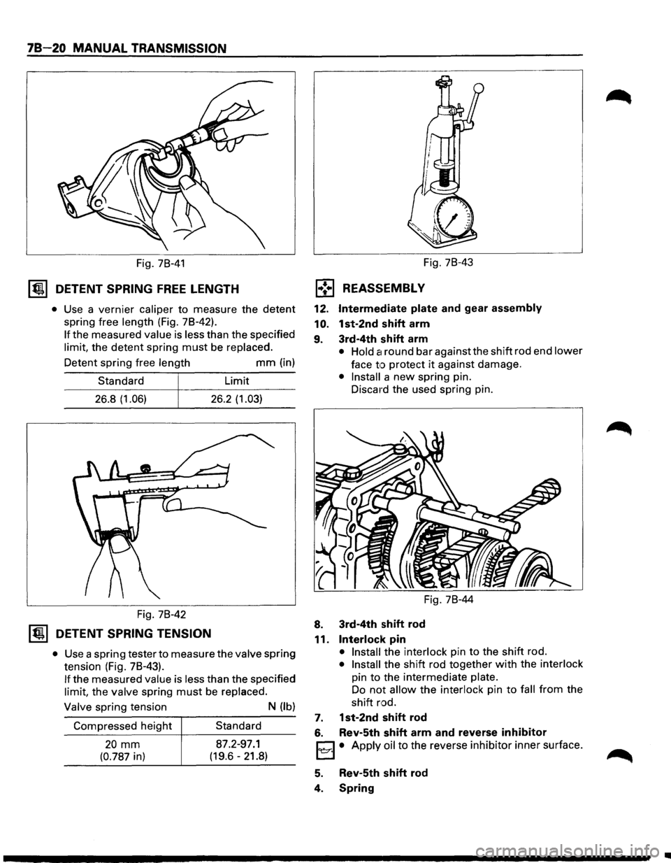
Fig. 78-41
~ DETENT SPRING FREE LENGTH
• Use a vernier caliper to measure the detent
spring free length (Fig. 78-42).
If the measured value is less than the specified
limit, the
detent spring must be replaced.
Detent spring free length
mm (in)
Standard Limit
26.8 (1.06) 26.2 (1.03)
Fig. 78-42
~ DETENT SPRING TENSION
• Use a spring tester to measure the valve spring
tension (Fig. 78-43).
If the measured value is less than the specified
limit, the valve spring must be replaced.
Valve spring tension
N (lb)
Compressed height Standard
20 mm 87.2-97.1
(0.787 in) (19.6-21.8) Fig.
78-43
l•!•l REASSEMBLY
12. Intermediate plate and gear assembly
10.
1st-2nd shift arm
9. 3rd-4th shift arm
• Hold Cl round bar against the shift rod end lower
face to protect it against damage.
• Install a new spring pin.
Discard the used spring pin.
Fig. 78-44
8. 3rd-4th shift rod
11. Interlock pin
• Install the interlock pin to the shift rod.
• Install the shift rod together with the interlock
pin
to the intermediate plate.
Do
not allow the interlock pin to fall from the
shift
rod.
7. 1st-2nd shift rod
6. Rev-5th shift arm and reverse inhibitor
EJ • Apply oil to the reverse inhibitor inner surface.
5. Rev-5th shift rod
4. Spring
..
Page 1112 of 1928
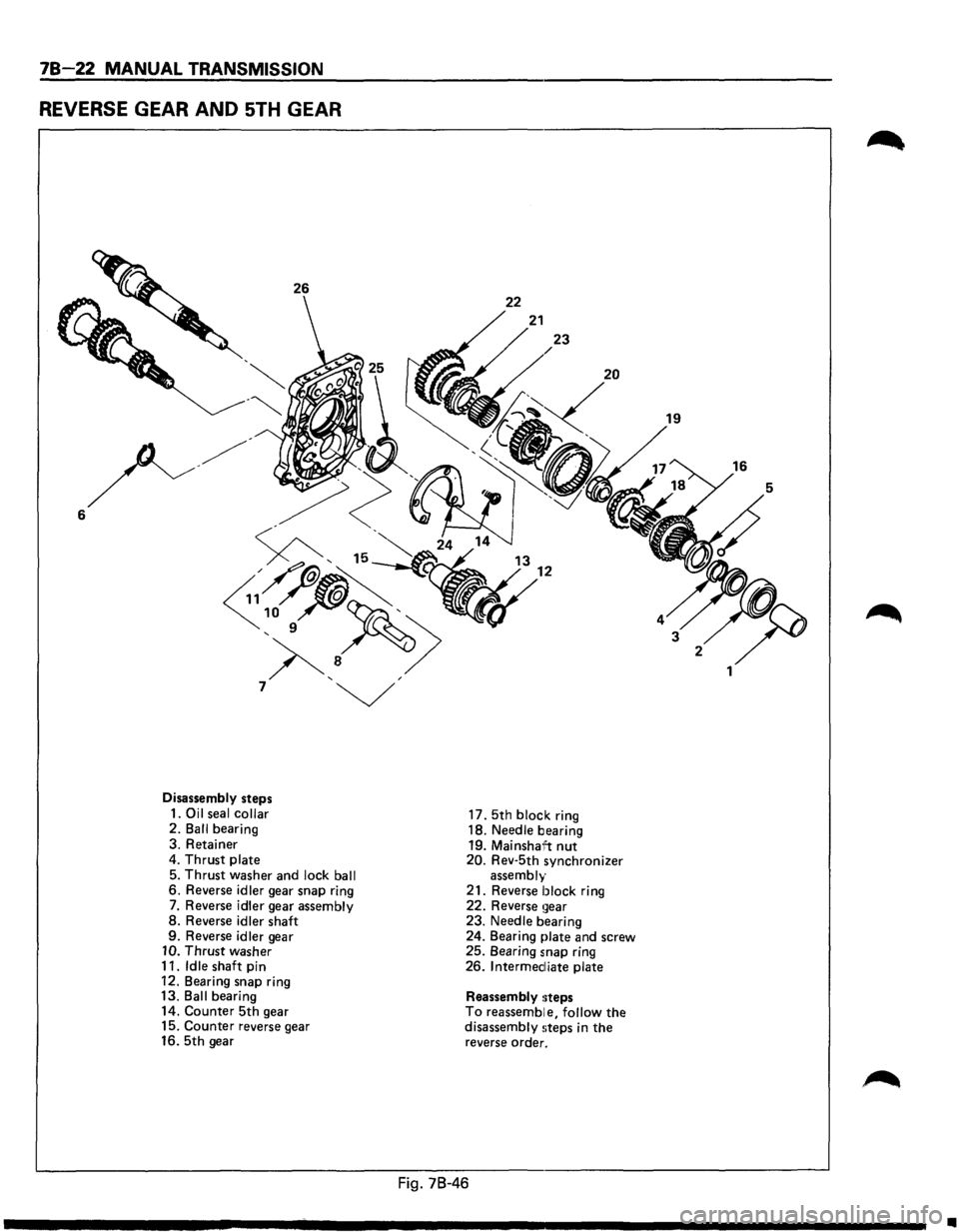
78-22 MANUAL TRANSMISSION
REVERSE GEAR AND 5TH GEAR
6
26 22
23
20
-~~ 19
-~;(>~-~~·
<:/'-. ~~2~
)<., ""-, 15~ 13
7 ~
Disassembly steps
1.
Oil seal collar 2. Ball bearing
3. Retainer
4.
Thrust plate
5. Thrust washer and lock ball 6. Reverse idler gear snap ring 7. Reverse idler gear assembly 8. Reverse idler shaft 9. Reverse idler gear 10. Thrust washer
11. Idle shaft pin
12. Bearing snap ring
13. Ball bearing
14. Counter 5th gear
15. Counter reverse gear
16. 5th gear 17.
5th block ring
18. Needle bearing
19.
Mainshai't nut 20. Rev-5th synchronizer assembly
21. Reverse block ring 22. Reverse !~ear 23. Needle bearing
24. Bearing plate and screw
25. Bearing snap ring
26. Intermediate plate
Reassembly !lteps To reassemble, follow the disassembly !iteps in the reverse order.
Fig. 78-46
5
..
Page 1113 of 1928
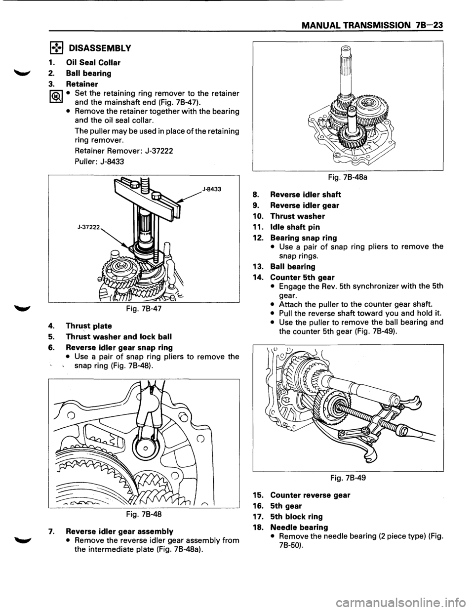
l•!•l DISASSEMBLY
1. Oil Seal Collar
2. Ball bearing
3. Retainer
I®J • Set the retaining ring remover to the retainer
and the mainshaft end (Fig. 78-47).
• Remove the retainer together with the bearing
and the
oil seal collar.
The puller may be used in place ofthe retaining
ring remover.
Retainer Remover: J-37222
Puller: J-8433
Fig. 78-47
4. Thrust plate
5. Thrust washer and lock ball
6. Reverse idler gear snap ring
J-8433
• Use a pair of snap ring pliers to remove the
snap ring (Fig. 78-48).
Fig. 78-48
7. Reverse idler gear assembly
• Remove the reverse idler gear assembly from
the intermediate plate (Fig. 78-48a).
MANUAL TRANSMISSION 78 23
Fig. 78-48a
8. Reverse idler shaft
9. Reverse idler gear
1
0. Thrust washer
11.
Idle shaft pin
12. Bearing snap ring
• Use a pair of snap ring pliers to remove the
snap rings.
13. Ball bearing
14. Counter 5th gear
• Engage the Rev. 5th synchronizer with the 5th
gear.
• Attach the puller to the counter gear shaft.
• Pull the reverse shaft toward you and hold it.
• Use the puller to remove the ball bearing and
the counter 5th gear (Fig. 78-49).
Fig. 78-49
15. Counter reverse gear
16. 5th gear
17. 5th
block ring
18.
Needle bearing
• Remove the needle bearing (2 piece type) (Fig.
78-50).