lock ISUZU TROOPER 1995 Manual PDF
[x] Cancel search | Manufacturer: ISUZU, Model Year: 1995, Model line: TROOPER, Model: ISUZU TROOPER 1995Pages: 1928
Page 253 of 1928
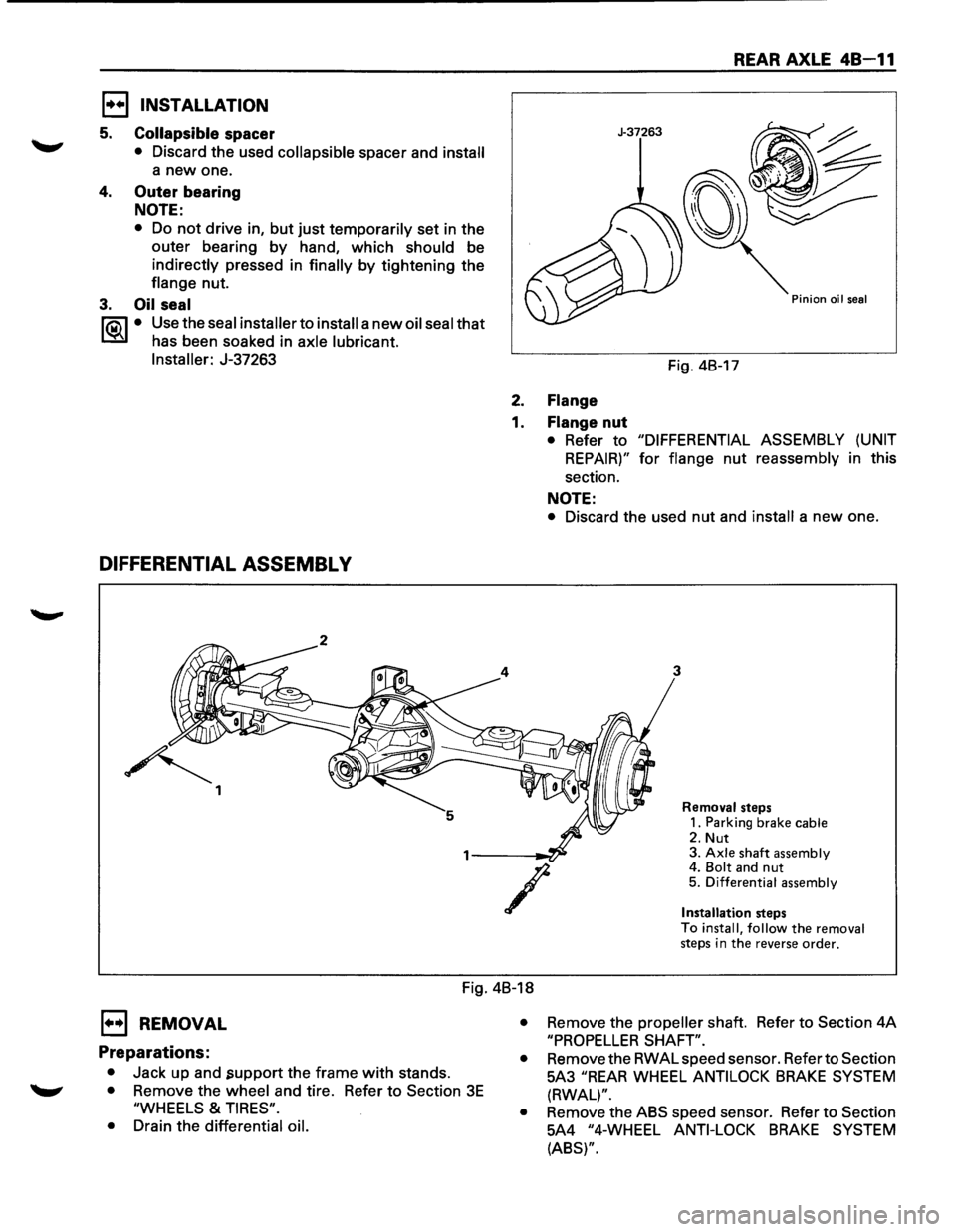
E) INSTALLATION
5. Collapsible spacer
• Discard the used collapsible spacer and install
a new one.
4. Outer bearing
NOTE:
• Do not drive in, but just temporarily set in the
outer bearing
by hand, which should be
indirectly pressed in finally by tightening the
flange nut.
3. Oil seal
1"?.:\1 • Use the seal installer to install a new oil seal that
l.::::'i:il has been soaked in axle lubricant.
Installer:
J-37263
DIFFERENTIAL ASSEMBL V
~ 1
REAR AXLE 48-11
J-37263
Pinion oil seal
Fig. 4B-17
2. Flange
1. Flange nut
• Refer to "DIFFERENTIAL ASSEMBLY (UNIT
REPAIR)" for flange nut reassembly in this
section.
NOTE:
• Discard the used nut and install a new one.
3
/
Removal steps
1. Parking brake cable
2. Nut 3. Axle shaft assembly 4. Bolt and nut 5. Differential assembly
Installation
steps
To install, follow the removal steps in the reverse order.
Fig. 4B-18
E) REMOVAL
Preparations:
• Jack up and .support the frame with stands.
• Remove the wheel and tire. Refer to Section 3E
"WHEELS & TIRES".
•
Drain the differential oil. •
Remove
the propeller shaft. Refer to Section 4A
"PROPELLER SHAFT".
•
Remove the RWAL speed sensor. Refer to Section
5A3
"REAR WHEEL ANTILOCK BRAKE SYSTEM
(RWAL)".
•
Remove the ABS speed sensor. Refer to Section
5A4
"4-WHEEL ANTI-LOCK BRAKE SYSTEM
(ABS)".
Page 258 of 1928
48 -16 REAR AXLE
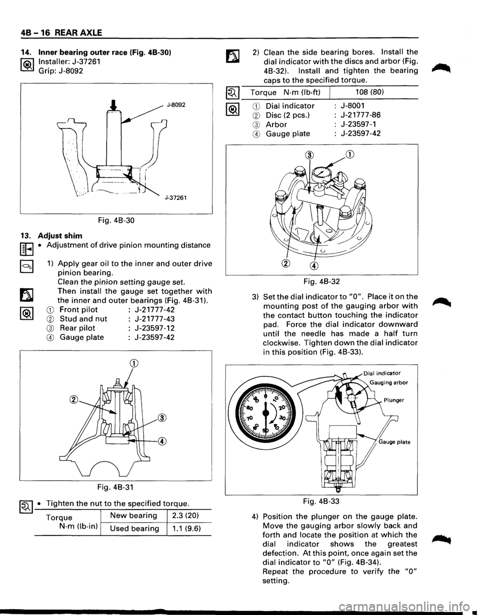
14. Inner bearing outer race (Fig. 48-30)
l®.llnstaller: J-37261
Grip: J-8092
J-8092
J-37261
Fig. 48-30
13. Adjust shim
UEI • Adjustment of drive pinion mounting distance
a 1) Apply gear oil to the inner and outer drive
pinion bearing.
Clean the pinion setting gauge set.
Then
install the gauge set together with
the inner and outer bearings (Fig. 48-31 ).
CD Front pilot J-21777-42
® Stud and nut J-21777-43
@ Rear pilot J-23597-12
@ Gauge plate J-23597-42
CD
Fig. 48-31
~~ 1-•-T_i..::..g_h_te_n_t_h_e_n_u...,t_t_o_t_h_e_s..:..p_e_c_if_ie_d_t-\
.-o_rq....:..._ue_. __
Torque New bearing 2.3 (20)
N-m (lb-in) Used bearing 1.1 (9.6)
2) Clean the side bearing bores. Install the
dial indicator with the discs and arbor (Fig.
48-32).
Install and tighten the bearing
caps to the specified torque.
~~~ Torque N-m (lb·ft) J 108 (80)
--------~----------1®.1 CD Dial indicator J-8001
® Disc (2 pes.) J-21777-86
@ Arbor J-23597-1
@ Gauge plate J-23597-42
Fig. 48-32
3) Set the dial indicator to "0". Place it on the
mounting post of the gauging arbor with
the contact button touching the indicator
pad. Force the dial indicator downward
until the needle has made a half turn
clockwise. Tighten down the dial indicator
in this position (Fig. 48-33).
Fig. 48-33
4) Position the plunger on the gauge plate.
Move the gauging arbor slowly back and
forth and locate the position at which the
dial indicator shows the greatest
defection. At this point, once again set the
dial indicator to "0" (Fig. 48-34).
Repeat
the procedure to verify the "0"
setting.
•
Page 265 of 1928
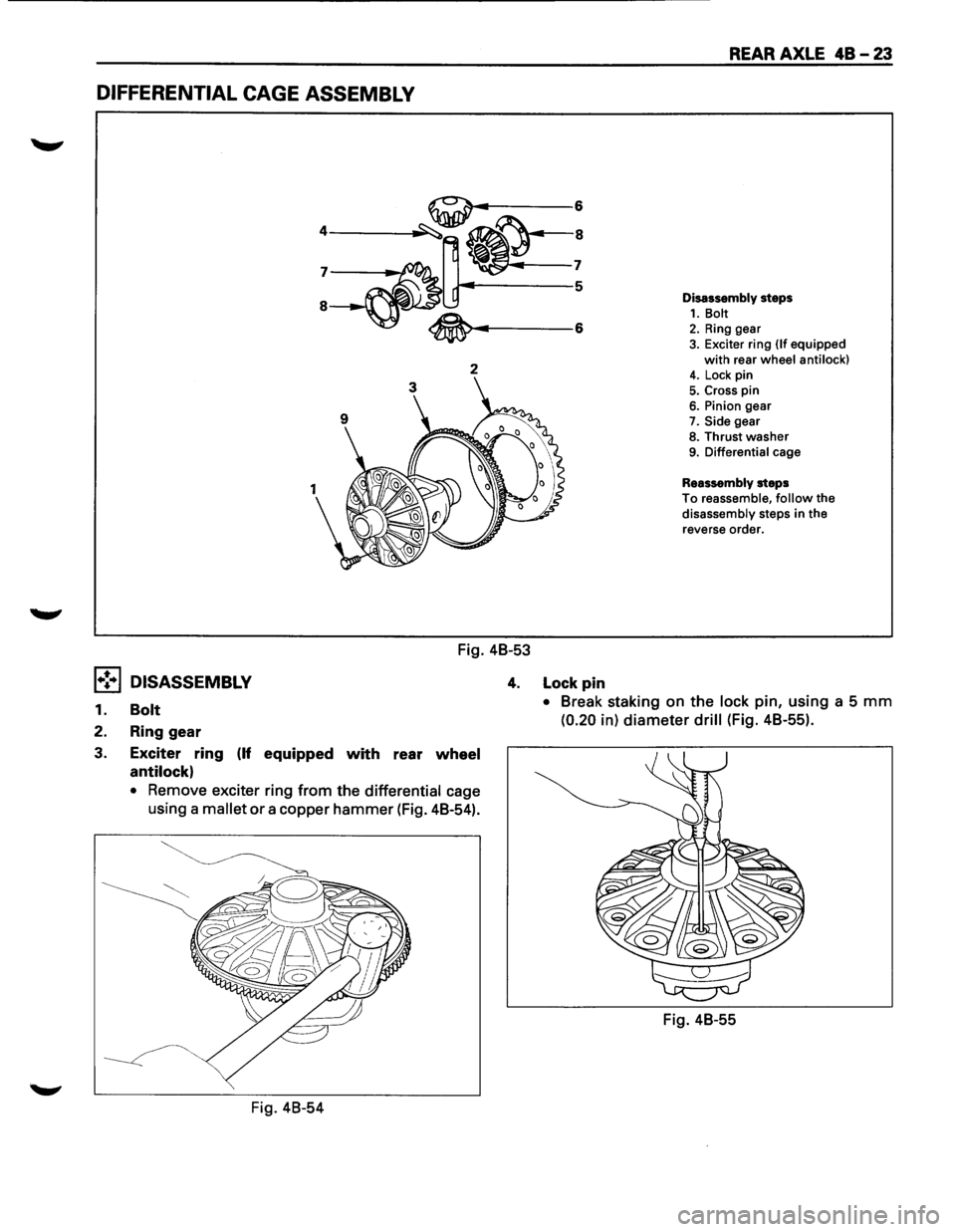
DIFFERENTIAL CAGE ASSEMBLY
2
Fig. 48-53
REAR AXLE 48-23
Disassembly steps 1. Bolt 2. Ring gear 3. Exciter ring (If equipped
with rear wheel anti lock) 4. Lock pin
5. Cross pin 6. Pinion gear
7. Side gear
8. Thrust washer 9. Differential cage
Reassembly steps
To reassemble, follow the
disassembly steps in the
reverse order.
1•! .. 1 DISASSEMBLY 4. Lock pin
1. Bolt
2. Ring gear
3. Exciter
ring (If equipped with rear wheel
antilock)
• Remove exciter ring from the differential cage
using a mallet
or a copper hammer (Fig. 48-54).
Fig. 48-54
• Break staking on the lock pin, using a 5 mm
(0.20 in) diameter drill (Fig. 48-55).
Fig. 48-55
Page 266 of 1928
48-24 REAR AXLE
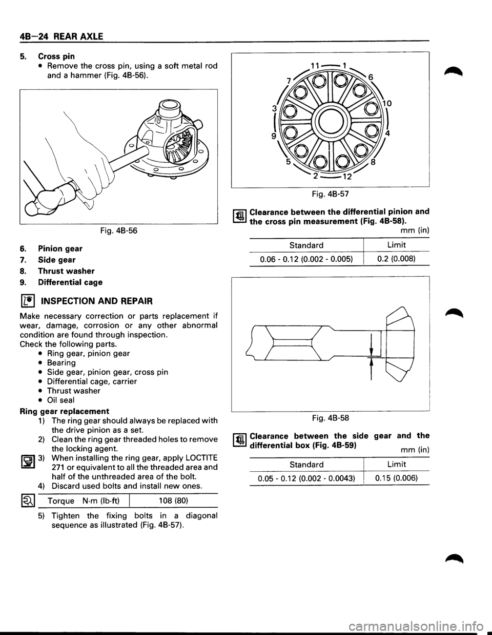
5. Cross pin
• Remove the cross pin, using a soft metal rod
and a hammer (Fig. 48-56).
Fig. 48-56
6. Pinion gear
7. Side gear
8. Thrust washer
9. Differential cage
(1!] INSPECTION AND REPAIR
Make necessary correction or parts replacement if
wear, damage, corrosion or any other abnormal
condition are found through inspection.
Check the following parts.
• Ring gear, pinion gear
• Bearing
• Side gear, pinion gear, cross pin
• Differential cage, carrier
• Thrust washer
• Oil seal
Ring gear replacement
1) The ring gear should always be replaced with
the drive pinion as a set.
2) Clean the ring gear threaded holes to remove
the
locking agent.
~~~3) When installing the ring gear, apply LOCTITE
271 or equivalent to all the threaded area and
half of the unthreaded area of the bolt.
4) Discard used bolts and install new ones.
1~1 Torque N·m (lb·ft) 108 (80)
5) Tighten the fixing bolts in a diagonal
sequence as illustrated (Fig. 48-57). Fig.
48-57
l'fil Clearance between the differential pinion and
1..!:.1 the cross pin measurement (Fig. 48-58).
mm (in)
Standard Limit
0.06 -0.12
(0.002 -0.005) 0.2
(0.008)
Fig. 48-58
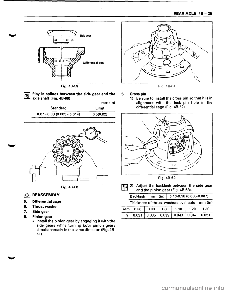
l'fil Clearance between the side gear and the
1..!:.1 differential box (Fig. 48-59) mm (in)
Standard
Limit
0.05 -0.12 (0.002 -0.0043) 0.1 5 (0.006)
Page 267 of 1928
Side gear
Differential box
Fig. 4B-59
l'fiil Play in splines between the side gear and the
1.!!.1 axle shaft (Fig. 48-60)
Standard
0.07-0.38 (0.003-0.014)
Fig. 4B-60
l•!•l REASSEMBLY
9. Differential cage
8.
Thrust washer
7. Side gear
6. Pinion gear
mm (in)
Limit
0.5(0.02)
• Install
the pinion gear by engaging it with the
side gears while turning both pinion gears
simultaneously in the same direction (Fig. 4B-
61).
REAR AXLE 48 - 25
Fig. 4B-61
5. Cross pin
1) Be sure to install the cross pin so that it is in
alignment with the lock pin hole in the
differential cage (Fig. 4B-62).
Fig. 4B-62
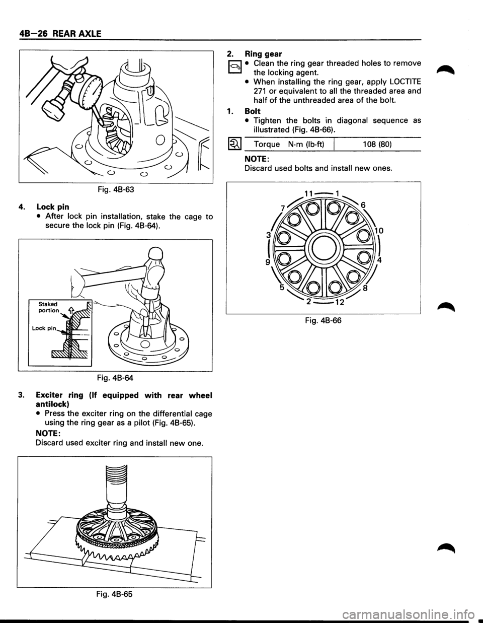
1§1-... 1 2) Adjust the backlash between the side gear
and the pinion gear (Fig. 4B-63).
Backlash mm (in) I 0.13-0.18 (0.005-0.007)
Thickness of thrust washers available mm (in)
mm 0.80 0.90 1.00
1.10 1.20
1.30
in 0.031
0.035 0.039 0.043
0.047 0.051
Page 268 of 1928
48-26 REAR AXLE
Fig. 48-63
4. Lock pin
• After lock pin installation, stake the cage to
secure the lock pin (Fig. 48-64).
Fig. 48-64
3. Exciter ring (If equipped with rear wheel
antilock)
• Press the exciter ring on the differential cage
using the ring gear
as a pilot (Fig. 48-65).
NOTE:
Discard used exciter ring and install new one.
Fig. 48-65
2. Ring gear
r;:::;J • Clean the ring gear threaded holes to remove
D the locking agent.
• When installing the ring gear, apply LOCTITE
271 or equivalent to all the threaded area and
half of the unthreaded area of the bolt.
1. Bolt
• Tighten the bolts in diagonal sequence as
illustrated (Fig. 48-66).
l~l Torque N·m (lb·ft) I 108 (80)
NOTE:
Discard used bolts and install new ones.
Fig. 48-66
Page 270 of 1928
48 -28 REAR AXLE
l•!-.1 DISASSEMBLY
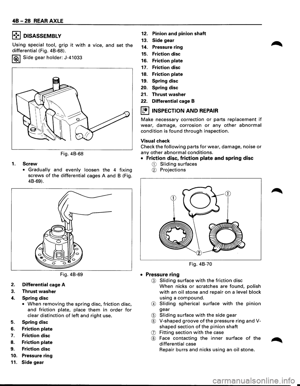
Using special tool, grip it with a vice, and set the
differential (Fig. 48-68).
I ®.1 Side gear holder: J-41 033
Fig. 48-68
1.
Screw
• Gradually and evenly loosen the 4 fixing
screws of the differential cages A and 8 (Fig.
48-69).
Fig. 48-69
2. Differential cage A
3. Thrust washer
4. Spring disc
• When removing the spring disc, friction disc,
and
friction plate, place them in order for
clear distinction of left and right use.
5. Spring disc
6. Friction plate
7. Friction disc
8. Friction plate
9. Friction disc
10. Pressure ring
11. Side gear
12. Pinion and pinion shaft
13. Side gear
14. Pressure
ring
15. Friction disc
16. Friction plate
17. Friction disc
18.
Friction plate
19. Spring disc
20. Spring disc
21.
Thrust washer
22. Differential cage B
IL•IINSPECTION AND REPAIR
Make necessary correction or parts replacement if
wear, damage, corrosion or any other abnormal
condition is found through inspection.
Visual check
Check
the following parts for wear, damage, noise or
any other abnormal conditions.
• Friction disc, friction plate and spring disc
CD Sliding surfaces
® Projections
Fig. 48-70
• Pressure ring
@ Sliding surface with the friction disc
When nicks or scratches are found, polish
with an oil stone and repair on a level block
using a
compound.
@ Sliding spherical surface with the pinion
gear
® Sliding surface with the side gear
® V-shaped groove of the pressure ring and V
shaped section
of the pinion shaft
(j) Fitting section with the case
® Face contacting the inner surface of the
differential case
Repair
burrs and nicks using an oil stone.
Page 278 of 1928
48-36 REAR AXLE
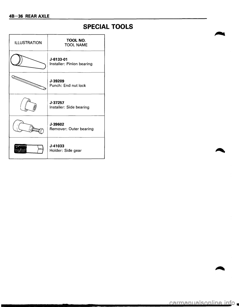
SPECIAL TOOLS
ILLUSTRATION TOOL NO.
TOOL NAME
J-6133-01
Installer: Pinion bearing
J-39209
Punch:
End nut lock
J-37257
Installer: Side bearing
J-39602
Remover: Outer bearing
J-41033
Holder: Side
gear
•
Page 279 of 1928
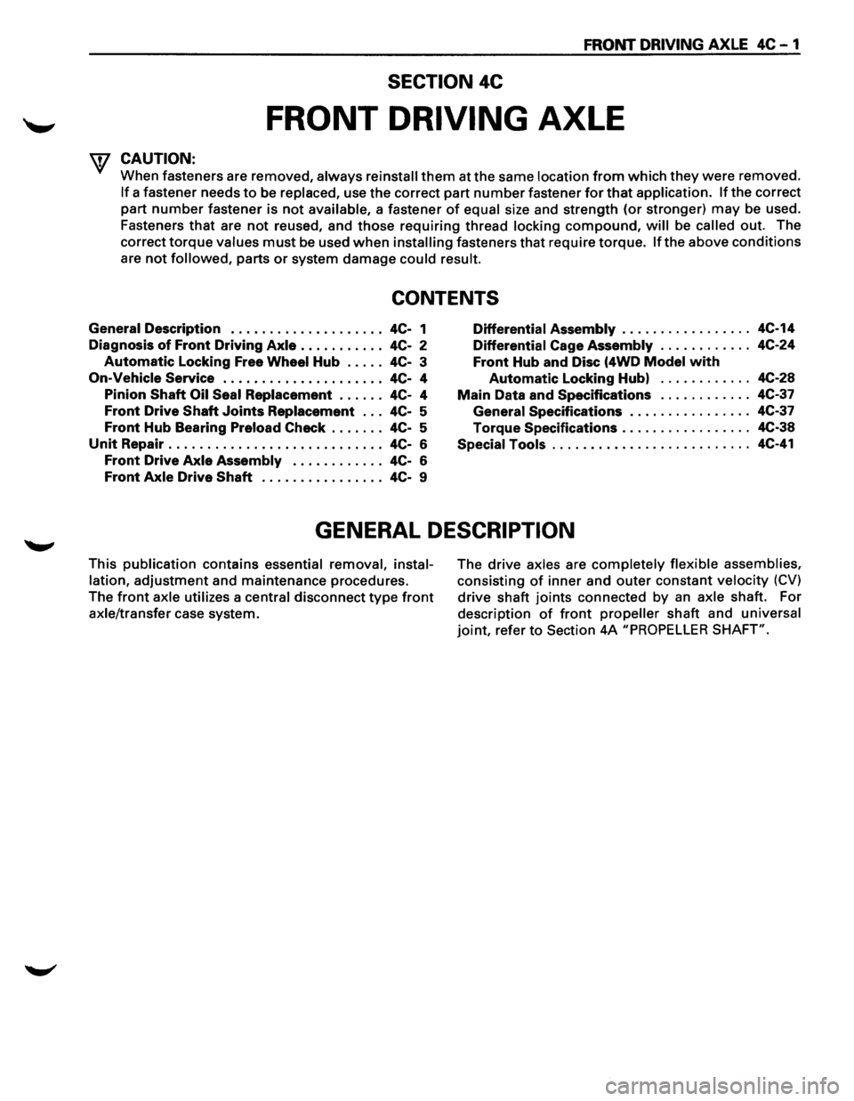
FRONT DRIVING AXLE 4C-1
SECTION 4C
FRONT DRIVING AXLE
'f CAUTION:
When fasteners are removed, always reinstall them at the same location from which they were removed.
If a fastener needs to be replaced, use the correct part number fastener for that application. If the correct
part
number fastener is not available, a fastener of equal size and strength (or stronger) may be used.
Fasteners
that are not reused, and those requiring thread locking compound, will be called out. The
correct
torque values must be used when installing fasteners that require torque. If the above conditions
are not followed, parts or system damage could result.
CONTENTS
General Description . . . . . . . . . . . . . . . . . . . . 4C-1
Diagnosis
of Front Driving Axle . . . . . . . . . . . 4C-2
Automatic Locking Free Wheel Hub . . . . . 4C-3
On-Vehicle Service ..................... 4C- 4
Pinion
Shaft Oil Seal Replacement . . . . . . 4C-4
Front Drive Shaft Joints Replacement . . . 4C-5
Front Hub Bearing Preload Check . . . . . . . 4C-5
Unit Repair . . . . . . . . . . . . . . . . . . . . . . . . . . . . 4C-6
Front Drive Axle Assembly . . . . . . . . . . . . 4C-6
Front Axle Drive Shaft . . . . . . . . . . . . . . . . 4C-9
Differential Assembly ................. 4C-14
Differential Cage Assembly . . . . . . . . . . . . 4C-24
Front Hub and Disc (4WD Model with
Automatic Locking Hub) . . . . . . . . . . . . 4C-28
Main Data and Specifications . . . . . . . . . . . . 4C-37
General Specifications . .
. . . . . . . . . . . . . . 4C-37
Torque Specifications ................. 4C-38
Special Tools .......................... 4C-41
GENERAL DESCRIPTION
This publication contains essential removal, instal
lation,
adjustment and maintenance procedures.
The
front axle utilizes a central disconnect type front
axle/transfer case system. The
drive axles are completely flexible assemblies,
consisting
of inner and outer constant velocity (CV)
drive shaft joints connected by an axle shaft. For
description
of front propeller shaft and universal
joint, refer to Section 4A "PROPELLER SHAFT".
Page 281 of 1928
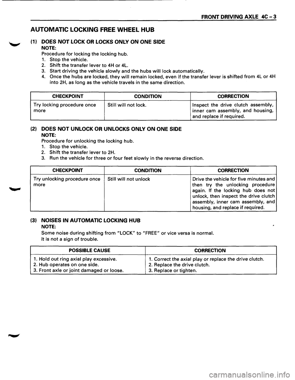
AUTOMATIC LOCKING FREE WHEEL HUB
(1) DOES NOT LOCK OR LOCKS ONLY ON ONE SIDE
NOTE:
Procedure for locking the locking hub.
1. Stop the vehicle.
2. Shift the transfer lever to 4H or 4L.
FRONT DRIVING AXLE 4C-3
3. Start driving the vehicle slowly and the hubs will lock automatically.
4. Once the hubs are locked, they will remain locked, even if the transfer lever is shifted from 4L or 4H
into 2H, as long as the vehicle travels in the same direction.
CHECKPOINT
CONDITION
Try locking procedure once Still will not lock.
more
(2) DOES NOT UNLOCK OR UNLOCKS ONLY ON ONE SIDE
NOTE:
Procedure for unlocking the locking hub.
1. Stop the vehicle.
2. Shift the transfer lever to 2H.
CORRECTION
Inspect the drive clutch assembly,
inner cam assembly, and housing,
and replace
if required.
3. Run the vehicle for three or four feet slowly in the reverse direction.
CHECKPOINT
CONDITION CORRECTION
Try unlocking procedure once Still will not unlock Drive the vehicle for five minutes and
more
(3) NOISES IN AUTOMATIC LOCKING HUB
NOTE:
then try the unlocking procedure
again.
If the locking hub does not
unlock, then inspect the drive clutch
assembly,
inner cam assembly, and
housing, and replace
if required.
Some noise during shifting from "LOCK" to "FREE" or vice versa is normal.
It
is not a sign of trouble.
POSSIBLE CAUSE CORRECTION
1. Hold out ring axial play excessive. 1. Correct the axial play or replace the drive clutch.
2. Hub operates on one side. 2. Replace the drive clutch.
3. Front axle or joint damaged or loose. 3. Replace or tighten.