engine ISUZU TROOPER 1995 Workshop Manual
[x] Cancel search | Manufacturer: ISUZU, Model Year: 1995, Model line: TROOPER, Model: ISUZU TROOPER 1995Pages: 1928
Page 1013 of 1928
AUTOMATIC TRANSMISSION (4L30-E) 7A-141
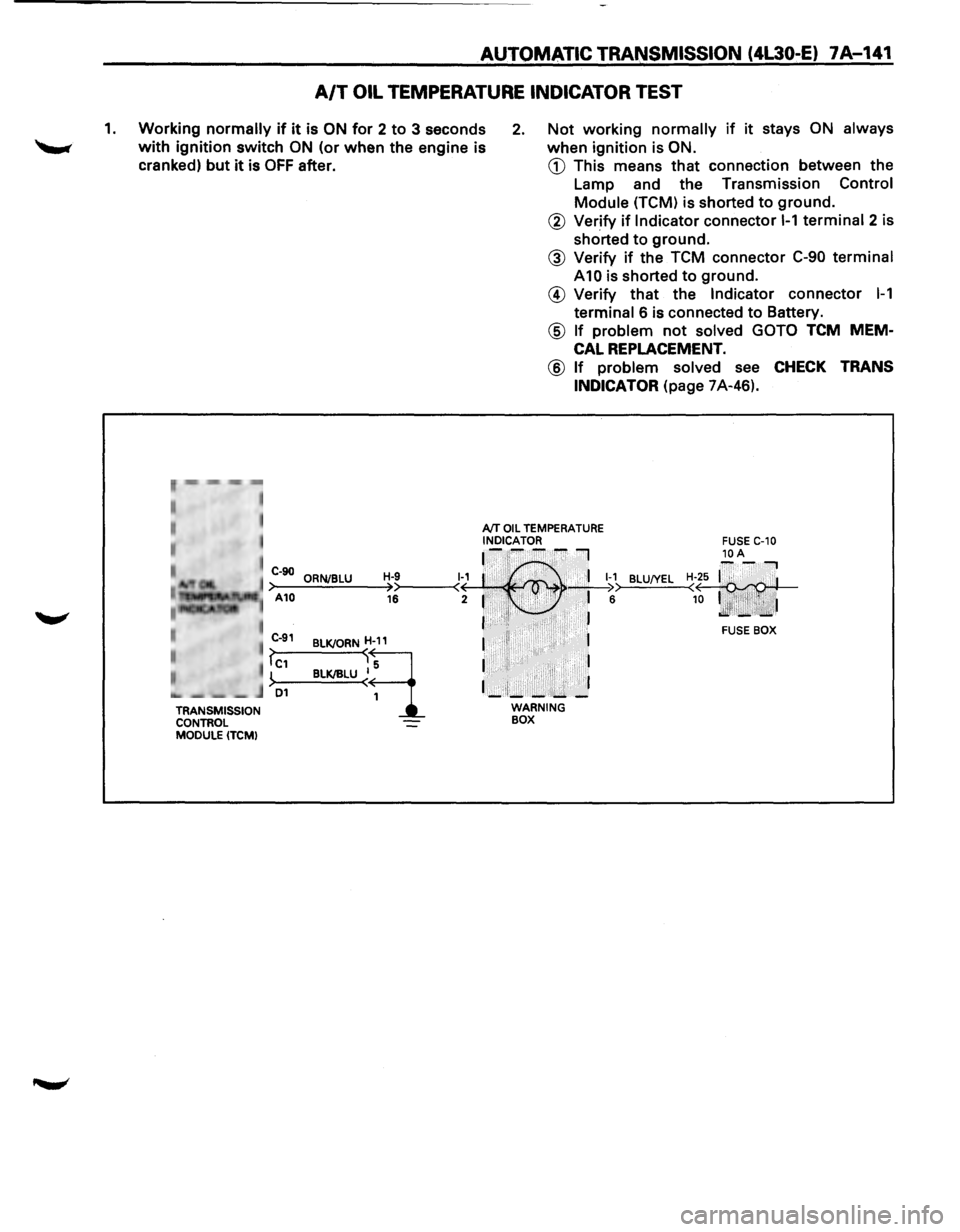
A/T OIL TEMPERATURE INDICATOR TEST
1. Working normally if it is ON for 2 to 3 seconds
with ignition switch ON (or when the engine is
cranked)
but it is OFF after.
2. Not working normally if it stays ON always
when ignition is ON.
CD This means that connection between the
Lamp and the Transmission
Control
Module (TCM) is shorted to ground.
r~,··mm -,-,~
• , I
I
TRANSMISSION
CONTROL
MODULE (TCM)
@ Verify if Indicator connector 1-1 terminal 2 is
shorted
to ground.
@ Verify if the TCM connector C-90 terminal
A10 is shorted to ground.
@ Verify that the Indicator connector 1-1
terminal 6 is connected to Battery.
@ If problem not solved GOTO TCM MEM
CAL REPLACEMENT.
@ If problem solved see CHECK TRANS
INDICATOR
(page 7A-46).
AfT OIL TEMPERATURE INDICATOR ~-~--~I
C-90 ORNJBLU H-9 1~1 :·' ,.· . 'I 1-1 >-A-10--=.:..;.;_;:,=-~>>----<( · , . ' >• • _;__I ;:. 16 2 1 . • .i· ,..:., • 6
I ·•'I• ·. . , . . J
BLU!YEL
BLKJORND
BLK/IILU ~~
I II 1
I I
1_:1;_-:....... _]
WARNING BOX
FUSE BOX
Page 1017 of 1928
AUTOMATIC TRANSMISSION (4L30-E) 7 A-145
TCM PRECAUTONS
The TCM can be damaged by:
(1) The Electrostatic discharge
(2) The short circuit of some terminals to voltage
or to ground.
Electrostatic Discharge Damage Description:
(1) Electronic components used to control systems
are often designed
to carry very low voltage,
and are
very susceptible to damage caused by
electrostatic discharge. It is possible for less
than 100 volts of static electricity to cause
damage
to some electronic components. By
comparison,
it takes as much as 4000 volts for
a person to even feel the zap of a static
discharge.
(2) There are several
ways for a person to become
statically charged. The most common methods
of charging are by friction and induction. An
example
of charging by friction is a person
sliding across a car seat, in
which a charge of
as much as 25,000 volts can build up.
Charging
by induction occurs when a person
with well insulated shoes stands near a highly
charged object and momentarily touches
ground. Charges for the same polarity are
drained off, leaving the person
highly charged
with the opposite polarity. Static charges of
either type can cause damage, therefore, it is
important to use care when handling and
testing electronic components.
NOTICE: To prevent possible Electrostatic
Discharge damage:
(1) Do not touch the TCM connector pins or
soldered components on the TCM circuit
board.
(2) When handling a Mem-Cal (PROM), do not
touch the component leads, and do not
remove integrated circuit from carrier.
(3) Be sure to follow the guidelines listed below if
servicing any of these electronic components:
(4) Do not open the replacement part package
until
it is time to install the part.
(5)
Avoid touching electrical terminals of the part.
(6) Before removing the part from its package,
ground the package to a known good ground
on the vehicle.
(7) Always touch a known good ground before
handling the part. This step should be repeated
before installing
the part if the part has been
handled
while sliding across the seat, while
sitting down from a standing position or while
walking some distance.
INFORMATION ON TCM:
(1) The Transmission Control Module (TCM) is
located in the
driver compartment and is the
control center
of the electronic transmission
control system.
(2) The TCM must be maintained at a temperature
below 185°F (85°C) at all times. This is most
essential if the vehicle is put through a paint
baking process. The
TCM will become in
operative
if its temperature exceeds 85°C
(185°F). Therefore, it is recommended that the
TCM be removed or that temporary insulation
be placed around the
TCM during the time the
vehicle is in a paint oven
or other high
temperature process.
(3) The
TCM is designed to process the various
inputs and then respond by sending the
appropriate electrical signals
to control trans
mission upshift,
downshift, shift feel and
torque converter clutch engagement.
(4) The TCM constantly interprets information
from the various sensors, and controls the
systems
that affect transmission and vehicle
performance. By analyzing operational prob
lems, the
TCM is able to perform a diagnostic
function
by displaying DTC(s) and aid the
technician in making repairs.
PROM/MEM-CAL:
(1) Information for a specific engine and vehicle is
programmed using an integrated circuit called
a Programmable Read-Only
Memory (PROM).
It
is also called a MEM-CAL (Memory Cali
brator). This allows one model of controller to
be used for many different vehicles. The
PROM is located inside the TCM and has
information on the engine, transmission,
calibration., etc. While one
TCM part number
can be used by many vehicle lines, a PROM is
more specific and must be used only with the
right vehicles. For this reason, it is very
important to check the latest parts book and
Service Bulletin
information for the correct part
number when replacing a PROM.
Page 1023 of 1928
A4
D16
D9
C1
D1
D12
A7
AB
TRANSMISSION
A3 C10 C12
B9
A2
All A9 A10
BB C15
B6 C16
CONTROL
B3
B10 C14
C7
B4
D14
MODULE
D7 D6
D5
C5 D4 C6
B5
B12
(TCMI
A12 B11
DB
CB
AUTOMATIC TRANSMISSION (4l30-E) 7 A-151
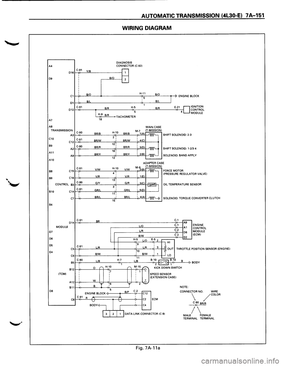
WIRING DIAGRAM
DIAGNOSIS
CONNECTOR (C-921 C-91
1: : j
B/0 B
I
I B/L
C-91 BIR :
G9 BIR 18
C-90 BRIB )
C-91 ) BR!W
C-90
BRIR I
I BR/Y )
C-91 V/W
'
' VIR )
C-90 G/Y
C-91 GRIL ) '
' BRIL :
C-91 BR
C-91 UR
: B/W
C-90 LIB )
;&"
r-r ,7 ' '
' '
' '
rt' w ,6
' B '
1---+: 5
ENGINE BLOCK •I C-91 R v
BODY•I~
H-11 B/0
'::5 B/L
1
H-5 BIR
(( 5
J
II• ENGINE B LOCK
E-~1 GNITION
ONTROL
MODULE ( 4 c
TACHOMETER
H-10
BRIB 'I 2 I
,J BR!W
I BRIR 16, ' BR/Y (( 12
H-10
4 ~ VC:!:f._
,j VIR
' GIR 3, ' GRIL ,,'~ ' BRIL (( 15
H-7 ((1
---
'r
B/P
1
v
I
MAIN CASE M-71(1 IT-MISSION) /1 A -'m'-SHIFT SOLENOID: 2-3 I I 4(C
: 3(0 -'m'-SHIFT SOLENOID: 1-2 /3-4
:, 21B -'100"'--SOLENOID: BAND AP PLY
ADAPTER
CASE
M-6211 IT-MISSION) FORCE MOTOR I 2 B
~ : liE (PRESSURE REGULAT OR VALVE)
I : 31C rAAUr1 '-== : SID I :, 41A ~I•
uo
UR
B/W
H-5
E 1-5 2 ~9 LIO
'
OIL TEMPERATURES
SOLENOID:
TORQUE
C-1 ..---A9 C-1 A1 C-2 D6 C-2
.-----.£L HI .?
ENSOR
CONVERTER CLUTCH
ENGINE CONTROL
MODULE (ECMI
\,o LIR < 3 OUT THROTTLE P OSITION SENSOR (ENGINE) ; B/W
' 1 LO 11 B-~10 LIB B ( 2 1 ~) II• BODY
"] "" oow' ""''" 1 -
: SPEED SENSOR : (EXTENSION CASE I ' + 2 NOTE:
't]
CONNEC
C12
: C2 ECM
C4 TOR
NO. WIRE /COLOR
~90 BRIR
I 3 I 2 I 1 I DATA LINK CONNECTOR (C-91 / MALE FEMALE TERMINAL TERMINAL
Fig.
7A-11a
Page 1024 of 1928
•
, cCi" -.J )> I .... N
RELAY
& FUSE BOX
(FL-1, FL-2, FL-3)
THROTTLE BODYASM SPEED SENSOR
ECM:
ENGINE CONTROL
MODULE
TCM:
TRANSMISSION CONTROL
MODULE
TP :THROTTLE
POSITION
ICM
: IGNITION CONTROL
MODULE
)
ECM
ICM(CONT) FRONT
CONSOLE
MODESW
MAIN
CASE
,}
~H-32
FUSE BOX
(C-3,
C-4,C-8,
C-10,
C-14)
BRAKE
SW
KICK DOWN
SW
ACCELERATOR PEDAL
1-9 INDICATOR LIGHT
(POWER, WINTER) 1-1 WARNING BOX (AfT
OIL
TEMP )
CHECK TRANS.
C-92 DIAGNOSIS CONNECTOR C-9 DATA
LINK CONNECTOR
}
(') 0 2
2 m a ::IJ r-0 (') !4 0 2
" t .... C1l N l> c: a s: !4 n -4 ::IJ l> 2 rA s: c;; rA 0 2 ~ ~ 0 I m
Page 1027 of 1928
... ......,.
AUTOMATIC TRANSMISSION (4L30-E) 7A-155
ON-VEHICLE SERVICE
CHECKING TRANSMISSION FLUID
LEVEL
1. Park the vehicle on level ground.
2. Apply the parking brake.
3. Place the automatic transmission in "Park" and
start the engine.
Allow the engine to idle for
two minutes.
4. With the brakes applied, move the shifter lever
through all the gear ranges, ending in "Park".
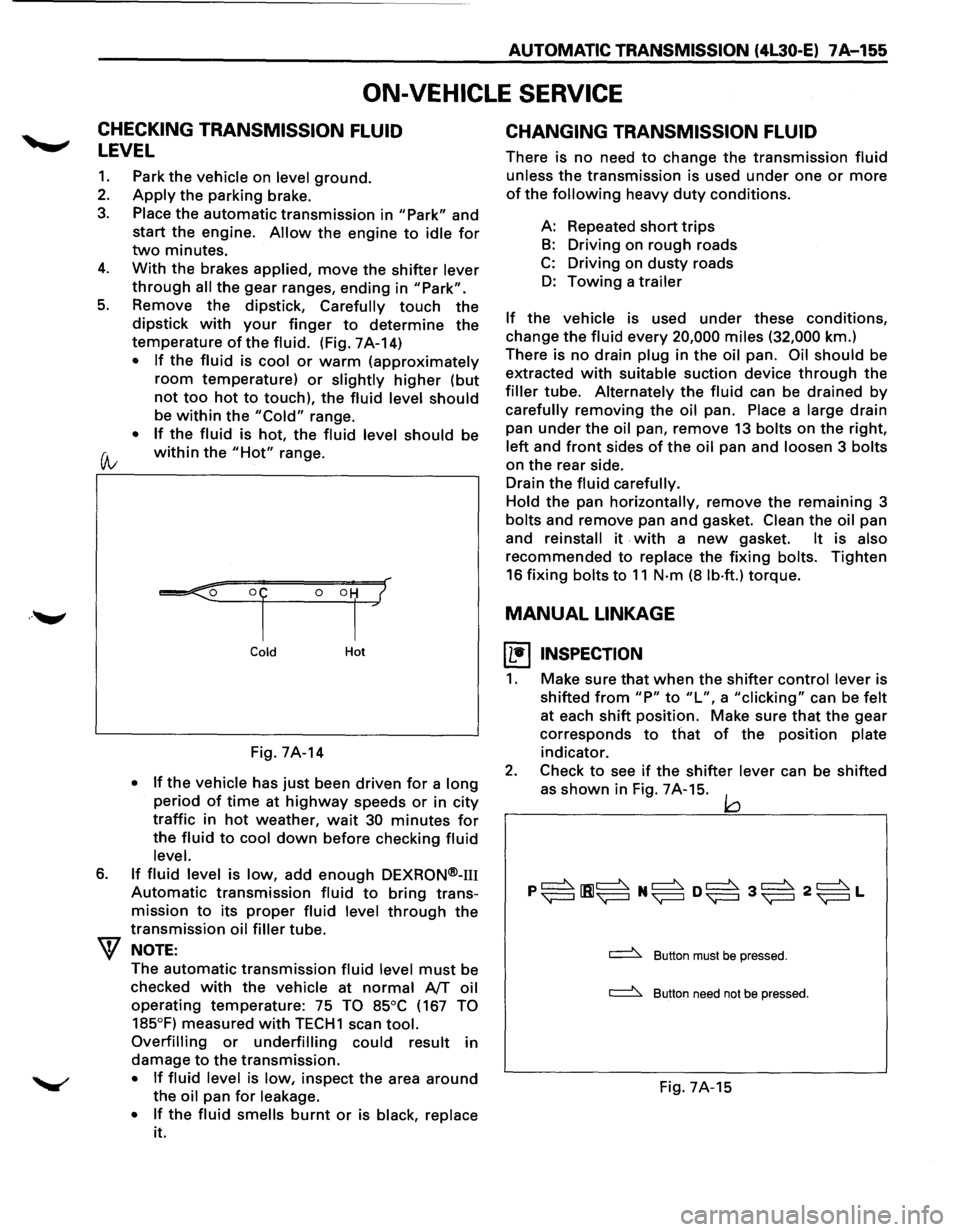
5. Remove the dipstick, Carefully touch the
dipstick with your finger to determine the
temperature of the fluid. (Fig. 7A-14)
• If the fluid is cool or warm (approximately
room temperature) or slightly higher (but
not too hot to touch), the fluid level should
be within the "Cold" range.
• If the fluid is hot, the fluid level should be
(A; within the "Hot" range.
6.
Cold Hot
Fig. 7A-14
• If the vehicle has just been driven for a long
period of time at highway speeds or in city
traffic in hot weather, wait 30 minutes for
the fluid to cool down before checking fluid
level.
If fluid level is low, add enough DEXRON®-m
Automatic transmission fluid to bring trans
mission
to its proper fluid level through the
transmission oil filler tube.
NOTE:
The automatic transmission fluid level must be
checked
with the vehicle at normal AfT oil
operating temperature: 75 TO 85°C (167 TO
185°F)
measured with TECH1 scan tool.
Overfilling or underfilling could result in
damage
to the transmission.
• If fluid level is low, inspect the area around
the oil pan for leakage.
•
If the fluid smells burnt or is black, replace
it.
CHANGING TRANSMISSION FLUID
There is no need to change the transmission fluid
unless the transmission is used under one or more
of the following heavy duty conditions.
A: Repeated
short trips
B: Driving on rough roads
C: Driving on dusty roads
D: Towing a trailer
If the vehicle is used under these conditions,
change the fluid every 20,000 miles (32,000 km.)
There is
no drain plug in the oil pan. Oil should be
extracted
with suitable suction device through the
filler tube. Alternately the fluid can be drained by
carefully removing the oil pan. Place a large drain
pan
under the oil pan, remove 13 bolts on the right,
left and front sides of the oil pan and loosen 3 bolts
on the rear side.
Drain
the fluid carefully.
Hold
the pan horizontally, remove the remaining 3
bolts and remove pan and gasket. Clean the oil pan
and
reinstall it . with a new gasket. It is also
recommended to replace the fixing bolts. Tighten
16 fixing bolts to 11 N·m (8 lb·ft.) torque.
MANUAL LINKAGE
~ INSPECTION
1. Make sure that when the shifter control lever is
shifted
from "P" to "L", a "clicking" can be felt
at each shift position. Make sure that the gear
corresponds
to that of the position plate
indicator.
2. Check to see if the shifter lever can be shifted
as
shown in Fig. 7A-15. jQ
~ Button must be pressed.
~ Button need not be pressed.
Fig. 7A-15
Page 1030 of 1928
7A-158 AUTOMATIC TRANSMISSION (4L30-E)
1. Mode switch cover
2.
Selector lever
• Disconnect selector lever from the mode
switch.
3. Heat protector
• Remove heat protector from the converter
housing. (Fig. 7A-18).
Fig. 7A-18
4. Air cleaner assembly
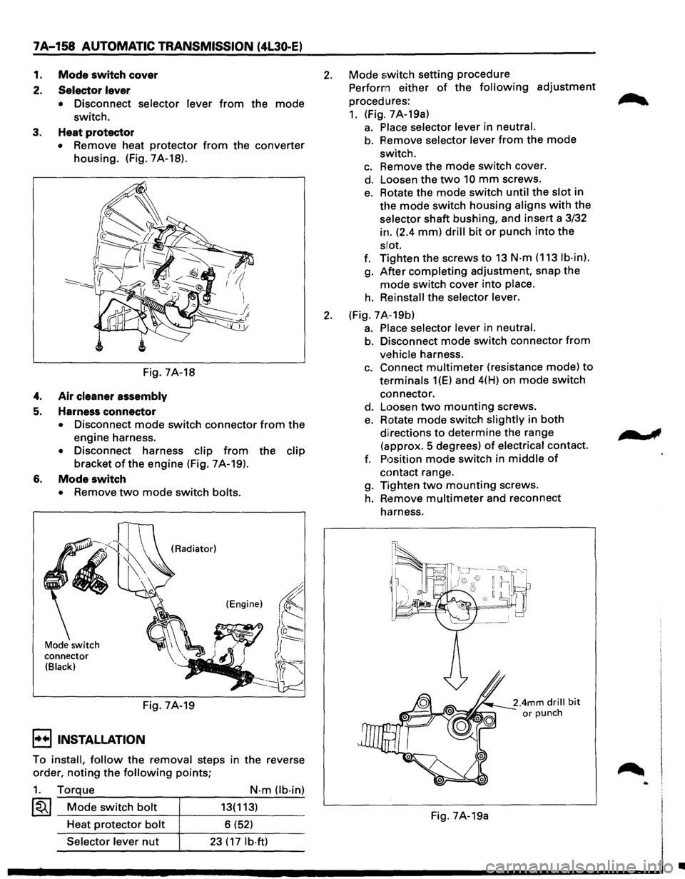
5. Harness connector
• Disconnect mode switch connector from the
engine harness.
• Disconnect harness clip from the clip
bracket ofthe engine (Fig. 7A-19).
6. Mode switch
• Remove two mode switch bolts.
Mode switch
connector
(Black)
(Radiator)
(Engine)
Fig. 7A-19
I••! INSTALLATION
To install, follow the removal steps in the reverse
order,
noting the following points;
1. Torque
~~~ Mode switch bolt
Heat protector bolt
Selector lever nut
N·m Ob·in)
13(113)
6 (52)
23 ( 17 lb·ft)
2. Mode switch setting procedure
Perform either
of the following adjustment
procedures:
1. (Fig. 7A-19a)
a. Place selector lever in neutral.
b. Remove selector lever from the mode
switch.
c. Remove the mode switch cover.
d. Loosen the
two 10 mm screws.
e. Rotate the mode switch until the slot in
the mode switch housing aligns with the
selector shaft bushing, and insert a 3/32
in. (2.4
mm) drill bit or punch into the
sllot.
f. Tighten the screws to 13 N·m (113 lb·in).
g. After completing adjustment, snap the
mode switch cover into place.
h. Reinstall the selector lever.
2. (Fig. 7 A.-19b)
a. Place selector lever in neutral.
b. Disconnect mode switch connector from
vehicle harness.
c. Connect multimeter (resistance mode) to
terminals 1(E) and 4(H) on mode switch
connector.
d.
Loosen two mounting screws.
e. Rotate mode switch slightly in both
diirections to determine the range
(approx.
5 degrees) of electrical contact.
f. Position
mode switch in middle of
contact range.
g. Tighten
two mounting screws.
h. Remove multimeter and reconnect
harness.
Fig. 7A-19a
..
•
Page 1032 of 1928
7A-160 AUTOMATIC TRANSMISSION (4L30-E)
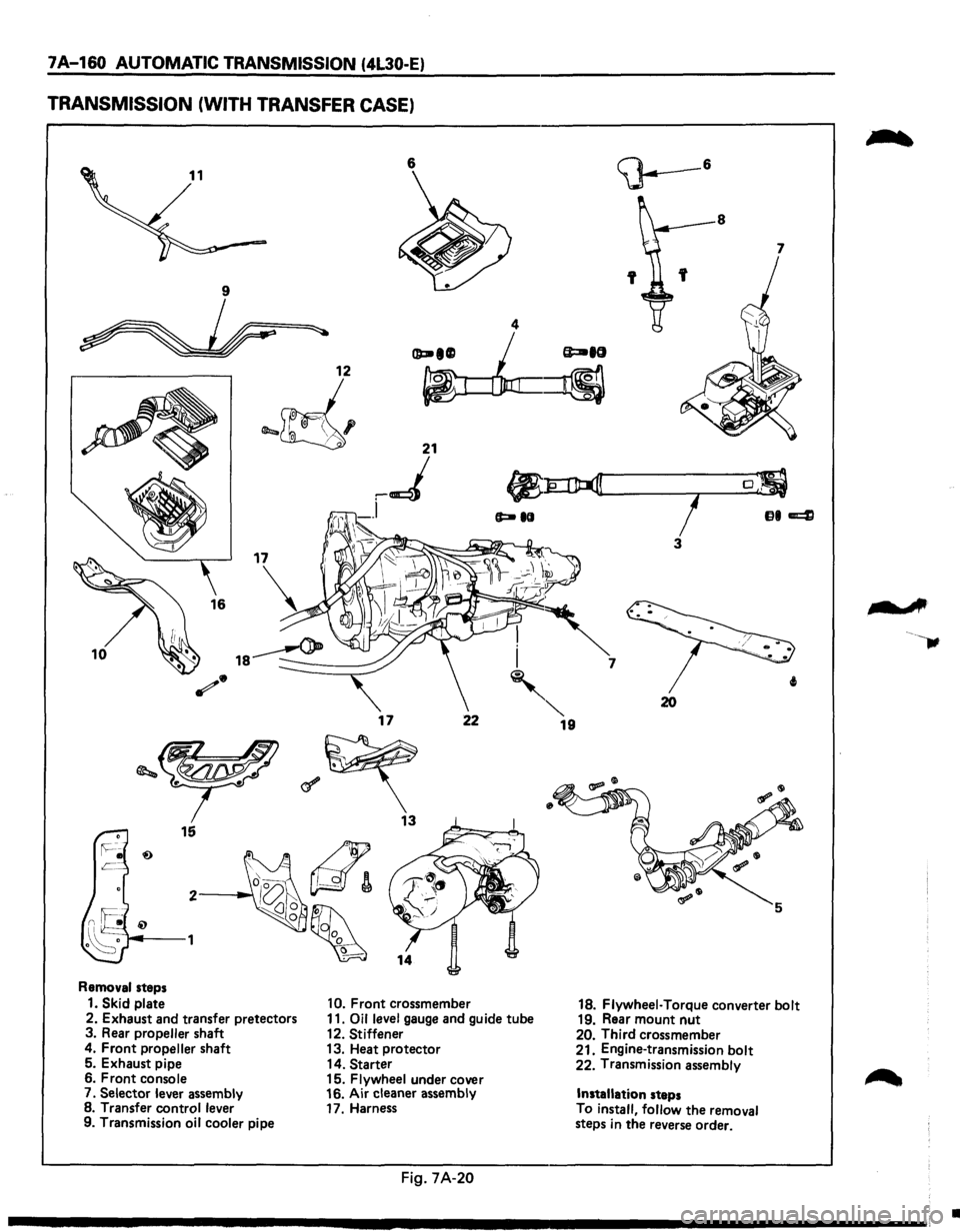
TRANSMISSION (WITH TRANSFER CASE)
6
I
10 i
'
17 22
Removal steps
1. Skid plate 10. Front crossmember
2. Exhaust and transfer pretectors 11. Oil level gauge and guide tube
3. Rear propeller shaft
12. Stiffener
4. Front propeller shaft 13. Heat protector
5. Exhaust pipe
14. Starter
6. Front console
15. Flywheel under cover
7.
Selector lever assembly 16.
Air cleaner assembly
8. Transfer control lever
17. Harness
9. Transmission
oil cooler pipe
Fig. 7A-20
""' 19
8
7
7
20
18. Flywheel· Torque converter bolt 19. Rear mount nut 20. Third crossmember
21. Engine-transmission bolt
22. Transmission assembly
Installation steps
To
install, follow the removal
steps in the reverse order.
-A
•
Page 1033 of 1928
1••1 REMOVAL
Preparation:
• Remove engine hood.
• Disconnect negative (-) battery cable.
1. Skid plate
2. Exhaust and transfer protectors
3. Rear propeller shaft
4. Front propeller shaft
5. Exhaust pipe
• Remove pre-catalytic converter, center pipe
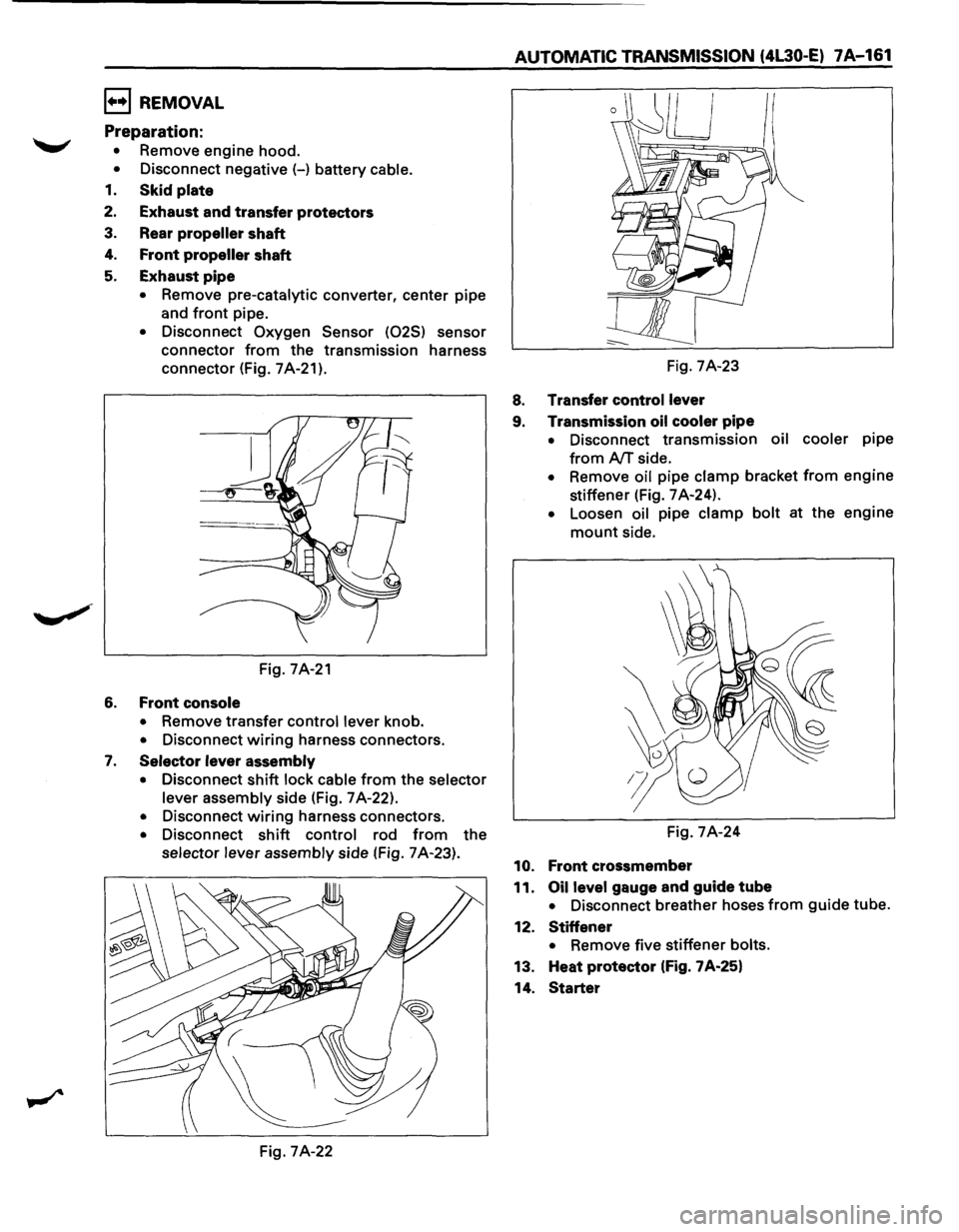
and
front pipe.
• Disconnect Oxygen Sensor (025) sensor
connector
from the transmission harness
connector (Fig.
7A-21).
Fig. 7A-21
6. Front console
• Remove transfer control lever knob.
• Disconnect wiring harness connectors.
7. Selector lever assembly
• Disconnect shift lock cable from the selector
lever assembly
side (Fig. 7 A-22).
• Disconnect wiring harness connectors.
• Disconnect shift control rod from the
selector lever assembly side (Fig. 7 A-23).
Fig. 7A-22
AUTOMATIC TRANSMISSION (4L30·E) 7A-161
Fig. 7A-23
8. Transfer control lever
9. Transmission oil cooler
pipe
• Disconnect transmission oil cooler pipe
from AfT side.
• Remove oil pipe clamp bracket from engine
stiffener (Fig.
7 A-24).
• Loosen oil pipe clamp bolt at the engine
mount side.
Fig.
7A-24
10. Front crossmember
11.
Oil level gauge and guide tube
• Disconnect breather hoses from guide tube.
12.
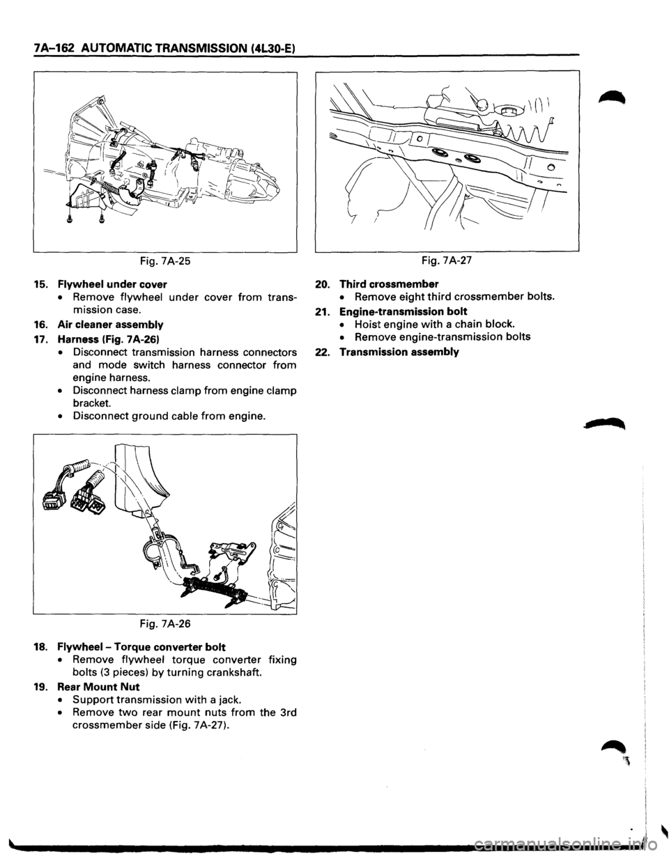
Stiffener
• Remove five stiffener bolts.
13. Heat protector (Fig. 7A-25}
14.
Starter
Page 1034 of 1928
7A-162 AUTOMATIC TRANSMISSION (4L30-E)
Fig. 7A-25
15. Flywheel under cover
• Remove flywheel under cover from trans
mission case.
16. Air cleaner assembly
17. Harness (Fig. 7A-26)
• Disconnect transmission harness connectors
and mode switch harness connector
from
engine harness.
• Disconnect harness clamp from engine clamp
bracket.
• Disconnect ground cable from engine.
Fig. 7A-26
18. Flywheel-Torque converter bolt
• Remove flywheel torque converter fixing
bolts (3 pieces) by turning crankshaft.
19. Rear Mount Nut
• Support transmission with a jack.
• Remove two rear mount nuts from the 3rd
crossmember side (Fig. 7A-27). Fig.
7A-27
20. Third cr·ossmember
• Remove eight third crossmember bolts.
21. Engine-transmission bolt
• Hoist engine with a chain block.
•
Remove engine-transmission bolts
22. Transmission assembly
Page 1035 of 1928
AUTOMATIC TRANSMISSION (4L30-E) 7A-163
I••IINSTALLALTION
To install, follow the removal steps in the reverse
order,
noting the following points;
22. Transmission assembly
•
Slowly raise transmission jack until front of
the transmission is aligned with rear of the
engine.
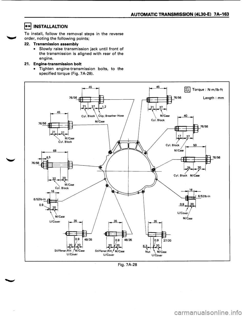
21. Engine-transmission
bolt
•
Tighten engine-transmission bolts, to the
specified
torque (Fig. 7A-28).
76/56
21 27 1.2
Cy~Bioc~21ip; Breather Hose
M/Case
68
Stiffener;R H M/Case U/Cover
Fig. 7A-28
45
35 ~ Torque : N·m/lb·ft
Length: mm
40
,---iEJE~I:=ll=1_::76/56
Cyl Blo~ r--1
M/Case J
1
-------e9E~~=~a.l_76/56
~ Cyl. Block M/Case
M/Case