engine ISUZU TROOPER 1995 Workshop Manual
[x] Cancel search | Manufacturer: ISUZU, Model Year: 1995, Model line: TROOPER, Model: ISUZU TROOPER 1995Pages: 1928
Page 1099 of 1928
12. Flywheel under cover bolts
• Install
three flywheel under cover bolts.
11. Gear control lever
• Install
the transmission control lever and
transfer
control lever.
• Install
the grommet assembly.
• Install
the front console assembly.
• Install
the gear control lever knob.
• Support the transfer case with a jack and then
remove the transmission jack
from
transmission side.
10. Front propeller shaft
• Install the front propeller shaft.
~~~ Torque N·m (lb·ft) 63 (46)
9. Front crossmember
• Install the front crossmember.
~~~ Torque N·m (lb·ft) 78 (58)
8. Engine rear mount
• Install the engine rear mount.
~~~ Torque N·m (lb·ft) 41 (30)
7. 3rd crossmember
• Install the 3rd crossmember.
1~1 Torque N-m (lb·ft) 50 (37)
6. Engine rear mount nuts
~~~ Torque N-m (lb·ft) 50 (37)
• Remove the transmission jack.
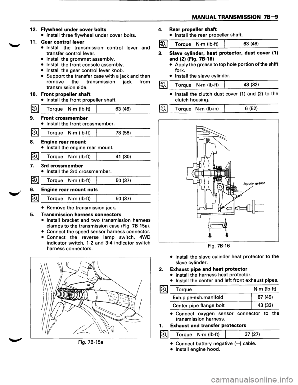
5. Transmission harness connectors
• Install bracket and two transmission harness
clamps to the transmission case (Fig. 78-15a).
• Connect the speed sensor harness connector.
• Connect the reverse lamp switch, 4WD
indicator
switch, 1-2 and 3-4 indicator switch
harness connectors.
Fig. 78-15a
MANUAL TRANSMISSION 78-9
4. Rear propeller shaft
• Install the rear propeller shaft.
I~I __ T_o_rq~u_e __ N_·m~(_lb_·ft~)~ _____ 6_3~(_46~) ____ _
3. Slave cylinder. heat protector. dust cover (1)
and (2) (Fig. 78-16)
• Apply the grease to top hole portion of the shift
fork.
• Install the slave cylinder.
~~~ Torque N·m (lb·ft) I 43 (32) _..:....__~----
• Install the clutch dust cover (1) and (2) to the
clutch housing.
~~~ Torque N·m (lb·in) 6 (52)
Apply grease
Fig. 78-16
• Install the slave cylinder heat protector to the
slave cylinder.
2. Exhaust pipe and heat protector
• Install the harness heat protector.
• Install the center and left front exhaust pipes.
~~~ Torque
Exh.pipe-exh.manifold
Center pipe
flange bolt N·m
(lb·ft)
67 (49)
43 (32)
• Connect oxygen sensor connector to the
transmission harness.
1. Exhaust and transfer protectors
~~~ Torque N·m (lb·ft) 37 (27)
• Connect battery negative (-) cable.
• Install
engine hood.
Page 1106 of 1928
78-16 MANUAL TRANSMISSION
7.
mm{in)
MAX. 1.5 (0.06)
MAX. 1.5 10.06)
MIN. 4 (0.16)
MIN. 4 (0.16)
Fig. 78-29
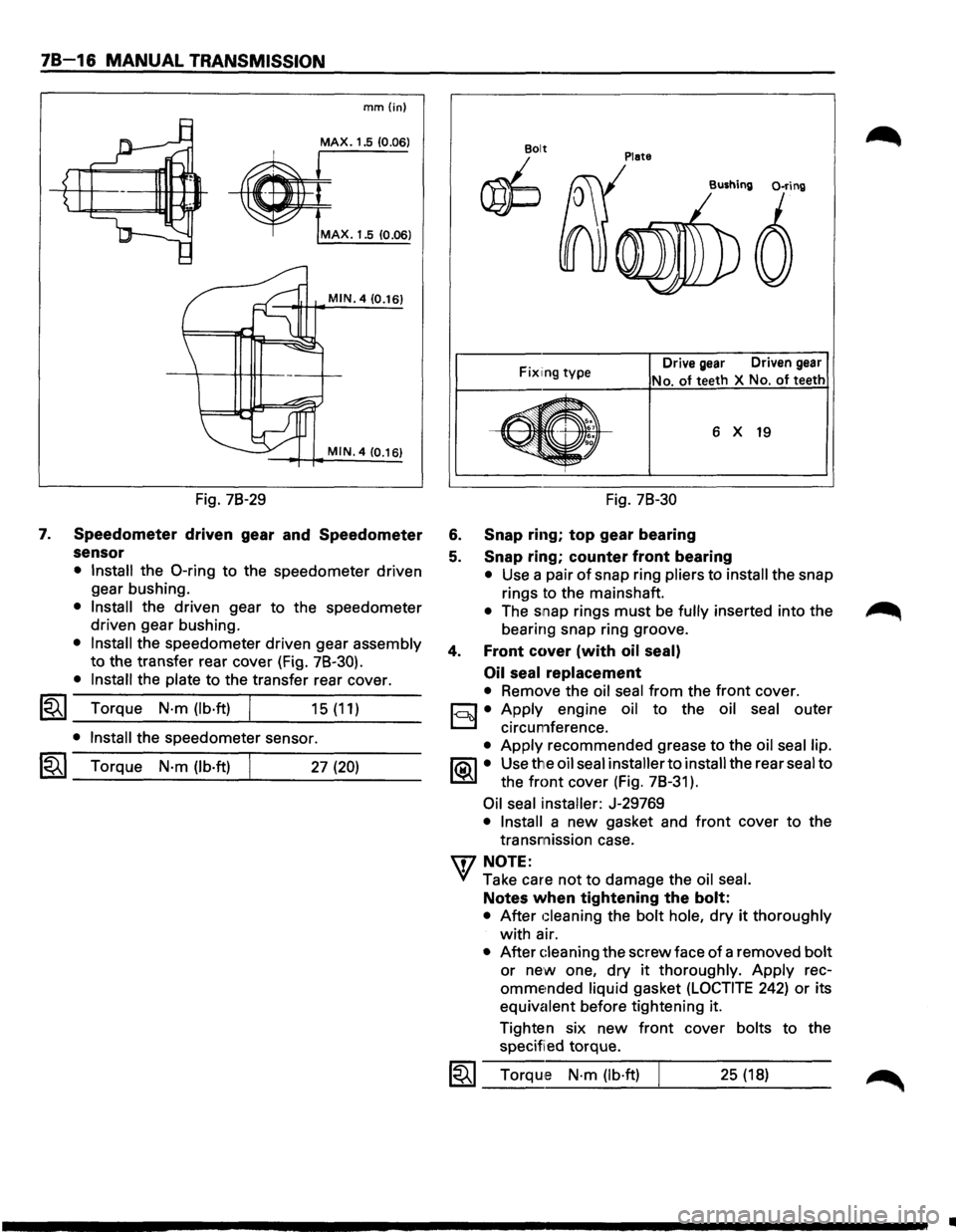
Speedometer driven gear and Speedometer
sensor
• Install the 0-ring to the speedometer driven
gear bushing.
• Install the driven gear to the speedometer
driven gear bushing.
• Install the speedometer driven gear assembly
to the transfer rear cover (Fig. 78-30).
• Install the plate to the transfer rear cover.
l"i't I Torque N·m (lb·ft) ~ _...:.____---~... ___ _ 15 (11)
• Install the speedometer sensor.
I~I_T_o_rq...;_u_e_N_·_m_(_lb_·ft_l----~. ___ 2_7_(2_0_) __ _
Plate Bolt
~
Fix1ing type Drive gear Driven gear
No. of teeth
X No. of teeth
6 X 19
Fig. 78-30
6. Snap ring; top gear bearing
5. Snap ring; counter front bearing
• Use a pair of snap ring pliers to install the snap
rings to the mainshaft.
• The snap rings must be fully inserted into the
bearing snap ring groove.
4. Front cover (with oil seal)
Oil seal
replacement
• Remove the oil seal from the front cover.
c:::;J • Apply engine oil to the oil seal outer
D circumference.
• Apply recommended grease to the oil seal lip.
1®.1• Use the oil seal installer to install the rear seal to
the
front cover (Fig. 78-31 ).
Oil seal installer: J-29769
• Install a new gasket and front cover to the
transmission case.
'\f7 NOTE:
"+({ Take care not to damage the oil seal.
Notes when tightening the bolt:
• After Gleaning the bolt hole, dry it thoroughly
with air.
• After Gleaning the screw face of a removed bolt
or new one, dry it thoroughly. Apply rec
omme~nded liquid gasket (LOCTITE 242) or its
equivalent before tightening it.
Tighten six
new front cover bolts to the
specified torque.
1~1 Torque N·m (lb·ft) 25 (18)
..
Page 1116 of 1928
78-26 MANUAL TRANSMISSION
Fig. 78-59
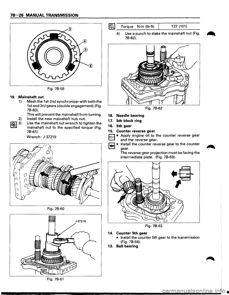
19. Mainshaft nut
1) Mesh the 1st-2nd synchronizer with both the
1st and 3rd gears
(double engagement) (Fig.
78-60).
2)
~3)
This will prevent the mainshaft from turning.
Install the new mainshaft hub nut.
Use the mainshaft
nut wrench to tighten the
mainshaft
nut to the specified torque (Fig.
78-61).
Wrench: J-37219
Fig. 78-60
Fig. 78-61
1~1 Torque N·m (lb·ft) 137 (101)
4) Use a punch to stake the mainshaft nut (Fig. ~
78-62).
18. Needle bearing
17. 5th
block ring
16. 5th gear
Fig. 78-62
15. Counter reverse gear
Cl • Apply engine oil to the counter reverse gear
L.::::::.l and the reverse gear.
8 • Install the counter reverse gear to the counter
gear.
The reverse gear projection
must be facing the
intermediate
plate. (Fig. 78-63).
Fig. 78-63
14. Counte1· 5th gear
• Install the counter 5th gear to the transmission
(Fig. 78-64).
13. Ball bearing
•
Page 1118 of 1928
78-28 MANUAL TRANSMISSION
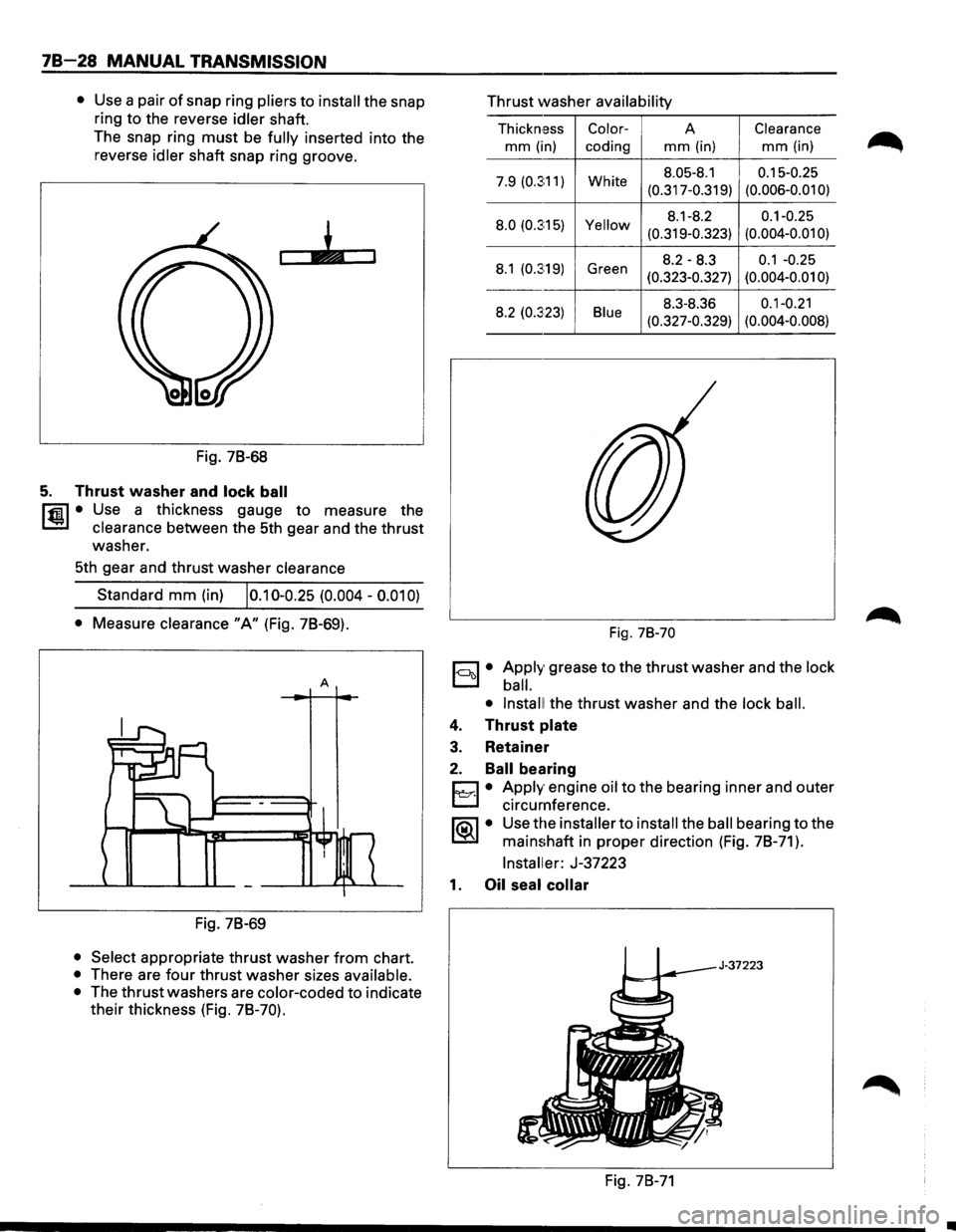
• Use a pair of snap ring pliers to install the snap
ring to the reverse
idler shaft.
The snap ring
must be fully inserted into the
reverse
idler shaft snap ring groove.
Fig. 78-68
5. Thrust washer and lock ball
l'fil • Use a thickness gauge to measure the
1.!::.1 clearance between the 5th gear and the thrust
washer.
5th gear and thrust washer
clearance
Standard mm (in) 10.10-0.25 (0.004 -0.01 0)
• Measure clearance "A" (Fig. 78-69).
A
Fig. 78-69
• Select appropriate thrust washer from chart.
• There are four thrust washer sizes available.
•
The thrust washers are color-coded to indicate
their thickness (Fig.
78-70).
Thrust washer availability
Thickn,ess Color-A Clearance
mm (in)
coding mm (in) mm (in)
7.9 (0.3:11) White 8.05-8.1 0.15-0.25
(0.317-0.319) (0.006-0.01
0)
8.0
(0.3:15) Yellow 8.1-8.2 0.1-0.25
(0.319-0.323) (0.004-0.01
0)
8.1 (0.3:19) Green 8.2-8.3 0.1 -0.25
(0.323-0.327) (0.004-0.01 0)
8.2 (0.323) Blue 8.3-8.36 0.1-0.21
(0.327-0.329) (0.004-0.008)
Fig. 78-70
1-ool • Apply grease to the thrust washer and the lock
ball.
• Install!
the thrust washer and the lock ball.
4. Thrust plate
3. Retainer
2. Ball bearing
D • Apply engine oil to the bearing inner and outer
~ circumference.
lia\1 • Use the installer to install the ball bearing to the
~ mainshaft in proper direction (Fig. 78-71 ).
Installer: J-37223
1. Oil seal collar
Fig. 78-71
•
Page 1124 of 1928
78-34 MANUAL TRANSMISSION
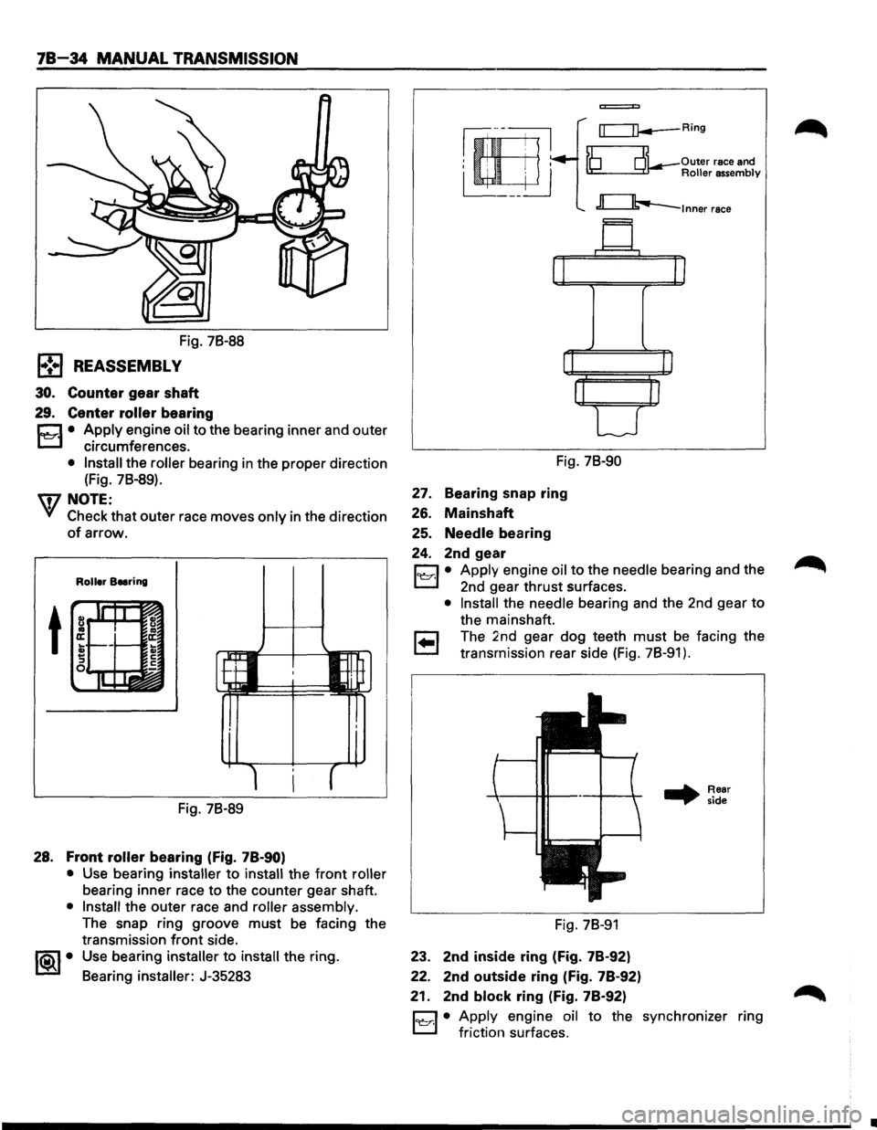
Fig. 78-88
l•!•l REASSEMBLY
30. Counter gear shaft
29. Center roller bearing
r:::::1 • Apply engine oil to the bearing inner and outer
L.:::.l circumferences.
• Install the roller bearing in the proper direction
(Fig. 78-89).
'q7 NOTE:
VI Check that outer race moves only in the direction
of arrow.
Roller Beering
t
Fig. 78-89
28. Front roller bearing (fig. 78-90)
• Use bearing installer to install the front roller
bearing inner race to the counter gear shaft.
• Install the outer race and roller assembly.
The snap ring groove must be facing the
transmission
front side.
1®..1• Use bearing installer to install the ring.
Bearing
installer: J-35283
=
rr=:=n--Ring
~ Outer race and ~Roller assembly
c:::Jb..-lnner race
Fig. 78-90
27. Bearing snap ring
26. Mainshaft
25. Needle bearing
24. 2nd gear
D • Apply engine oil to the needle bearing and the
L.:::.l 2nd gear thrust surfaces.
• Install the needle bearing and the 2nd gear to
the mainshaft.
r:;::] The 2nd gear dog teeth must be facing the
~ transmission rear side (Fig. 78-91 ) .
Fig. 78-91
23. 2nd inside ring (Fig. 78-92)
22. 2nd
outside ring (Fig. 78-92)
21. 2nd
bloc:k ring (Fig. 78-92)
.. Rear
side
D • Apply engine oil to the synchronizer ring
L.:::.l friction surfaces.
•
Page 1126 of 1928
78-36 MANUAL TRANSMISSION
Snap ring availability mm (in)
Thickness
Color-coding
1.80 (0.071)
White
1.85
(0.073) Yellow
1.90 (0.075)
Blue
•
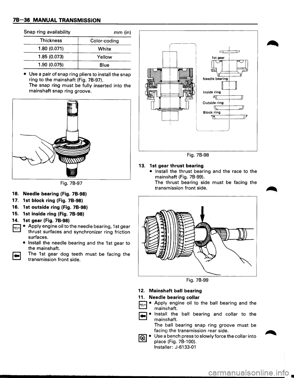
Use a pair of snap ring pliers to install the snap
ring
to the mainshaft (Fig. 78-97).
The snap ring
must be fully inserted into the
mainshaft snap ring groove.
Fig. 78-97
18. Needle bearing (Fig. 78-98)
17. 1st
block ring (Fig. 78-98)
16. 1st outside ring (Fig. 78-98)
15. 1st inside ring (Fig. 78-98)
14. 1st gear (Fig. 78-98)
C1 • Apply engine oil to the needle bearing, 1st gear
L::l thrust surfaces and synchronizer ring friction
surfaces.
• Install the needle bearing and the 1st gear to
the mainshaft.
1 .. 1 The 1st gear dog teeth must be facing the
transmission
front side.
c:;! j;::::J
Inside ring
Outside ring .
Block Zig I
~~ .
Fig. 78-98
13. 1st gear thrust bearing
• Install the thrust bearing and the race to the
mainshaft (Fig. 78-99).
The
thrust bearing side must be facing the
transmission
front side.
Fig. 78-99
12. Mainshaft ball bearing
11.
Needle bearing collar
1~·1 • Apply engine oil to the ball bearing and the
mainshaft.
1 .. 1• Install the ball bearing and collar to the
mainshaft.
The
ball bearing snap ring groove must be
facin~1 the transmission rear side.
1®..1 • Use a bench press to slowly force the collar into
place (Fig. 78-1 00).
Installer:
J-6133-01
Page 1127 of 1928
MANUAL TRANSMISSION 78-37
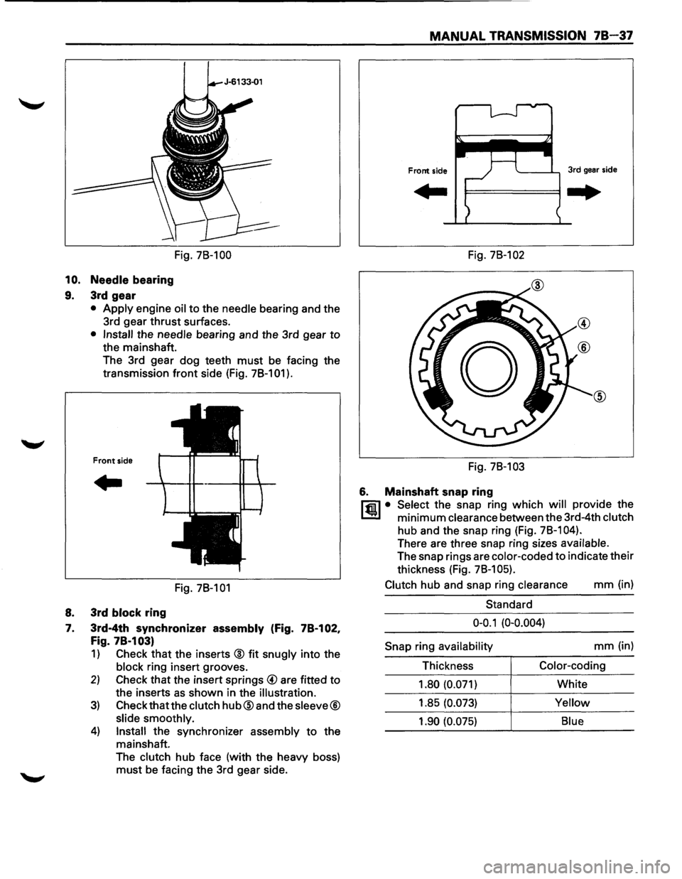
Fig. 78-100 Fig. 78-102
10. Needle bearing
9. 3rd gear
• Apply engine oil to the needle bearing and the
3rd gear
thrust surfaces.
• Install the needle bearing and the 3rd gear to
the mainshaft.
The 3rd gear dog teeth
must be facing the
transmission
front side (Fig. 78-101 ).
Front side
..
Fig. 78-101
8. 3rd block ring
7. 3rd-4th synchronizer assembly (Fig. 78-102,
Fig. 78·103)
1) Check that the inserts @ fit snugly into the
block ring insert grooves.
2) Check that the insert springs @ are fitted to
the inserts as shown in the illustration.
3) Check that the clutch hub@and the sleeve®
slide smoothly.
4) Install the synchronizer assembly to the
mainshaft.
The
clutch hub face (with the heavy boss)
must be facing the 3rd gear side. Fig.
78-103
6. Mainshaft snap ring
l"fil • Select the snap ring which will provide the
l..!l!l minimum clearance between the 3rd-4th clutch
hub and the snap ring (Fig. 78-1 04).
There are three snap ring sizes available.
The snap rings are color-coded to indicate their
thickness (Fig.
78-1 05).
Clutch
hub and snap ring clearance mm (in)
Standard
0-0.1 (0-0.004)
Snap
ring availability mm (in)
Thickness
Color-coding
1.80 (0.071)
White
1.85
(0.073) Yellow
1.90 (0.075) Blue
Page 1129 of 1928
MANUAL TRANSMISSION 78-39
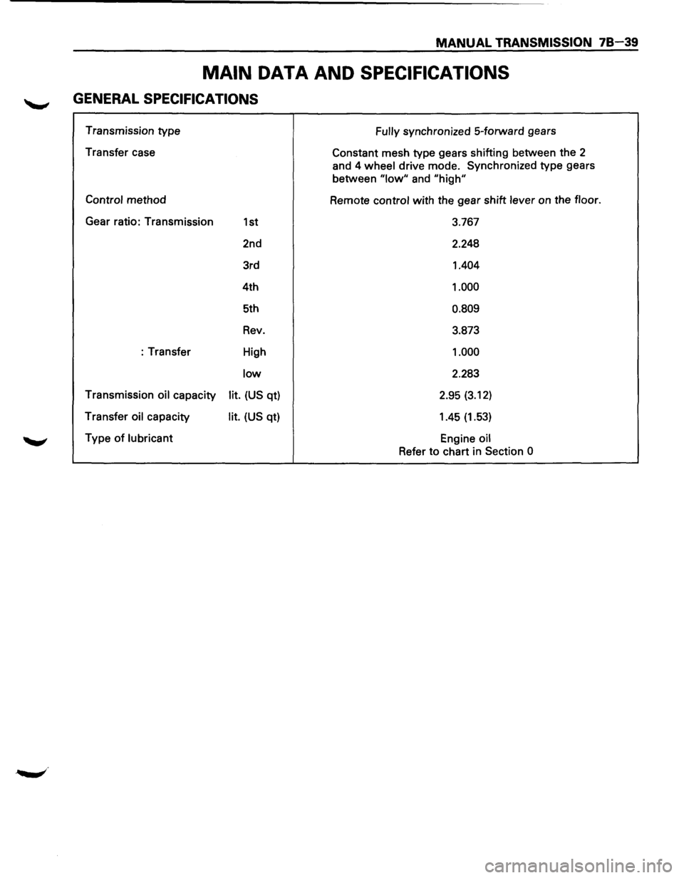
MAIN DATA AND SPECIFICATIONS
GENERAL SPECIFICATIONS
Transmission type
Transfer case
Control method
Gear ratio: Transmission
1st
2nd
3rd
4th
5th
Rev.
:Transfer High
low
Transmission oil capacity lit. (US qt)
Transfer
oil capacity lit. (US qt)
Type
of lubricant Fully
synchronized
5-forward gears
Constant mesh type gears shifting between the
2
and 4 wheel drive mode. Synchronized type gears
between
"low" and "high"
Remote control with the gear shift lever on the floor.
3.767
2.248
1.404
1.000
0.809
3.873
1.000
2.283
2.95
(3.12)
1.45 (1.53)
Engine oil
Refer to chart in Section 0
Page 1136 of 1928
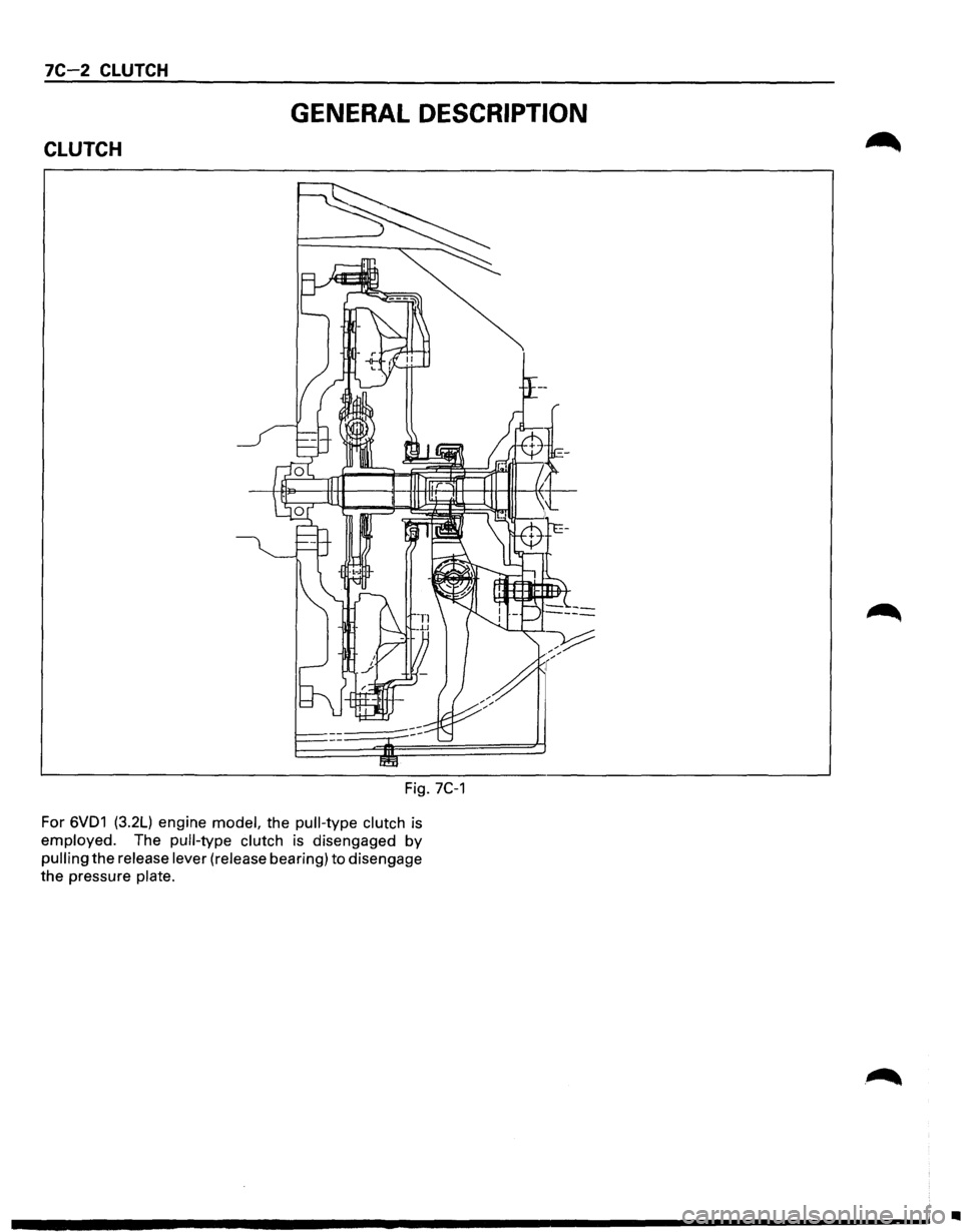
7C-2 CLUTCH
GENERAL DESCRIPTION
CLUTCH
Fig. 7C-1
For 6VD1 (3.2L) engine model, the pull-type clutch is
employed. The pull-type clutch is disengaged by
pulling the release lever (release bearing) to disengage
the pressure
plate.
•
Page 1139 of 1928
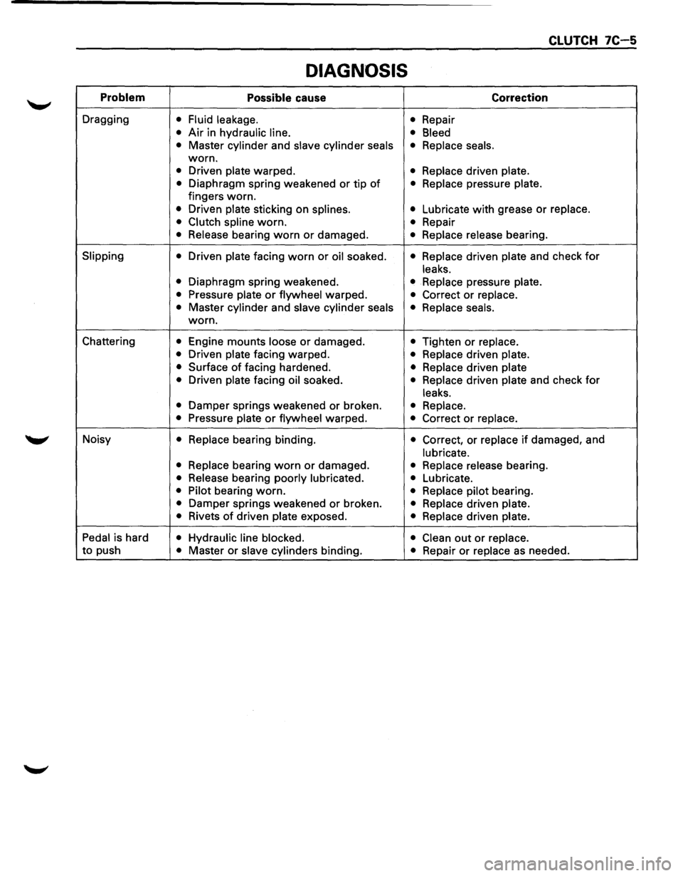
CLUTCH 7C-5
DIAGNOSIS
Problem Possible cause Correction
Dragging • Fluid leakage.
• Repair
• Air in hydraulic line.
• Bleed
•
Master cylinder and slave cylinder seals • Replace seals.
worn.
• Driven plate warped. • Replace driven plate.
•
Diaphragm spring weakened or tip of • Replace pressure plate.
fingers worn.
• Driven plate sticking on splines. • Lubricate with grease or replace.
• Clutch spline
worn. • Repair
• Release bearing worn or damaged. • Replace release bearing.
Slipping
• Driven plate facing worn or oil soaked. • Replace driven plate and check for
leaks.
•
Diaphragm spring weakened. • Replace pressure plate.
•
Pressure plate or flywheel warped. • Correct or replace.
•
Master cylinder and slave cylinder seals
• Replace seals.
worn.
Chattering
• Engine mounts loose or damaged. • Tighten or replace.
•
Driven plate facing warped. • Replace driven plate.
•
Surface of facing hardened. • Replace driven plate
•
Driven plate facing oil soaked. • Replace driven plate and check for
leaks.
•
Damper springs weakened or broken. • Replace.
•
Pressure plate or flywheel warped. • Correct or replace.
Noisy • Replace bearing binding. • Correct, or replace if damaged, and
lubricate.
• Replace
bearing worn or damaged. • Replace release bearing.
• Release bearing poorly lubricated.
• Lubricate.
• Pilot bearing worn. • Replace pilot bearing.
• Damper springs weakened or broken. • Replace driven plate.
•
Rivets of driven plate exposed. • Replace driven plate.
Pedal
is hard • Hydraulic line blocked.
• Clean out or replace.
to push • Master or slave cylinders binding. • Repair or replace as needed.