body JAGUAR X308 1998 2.G Workshop Manual
[x] Cancel search | Manufacturer: JAGUAR, Model Year: 1998, Model line: X308, Model: JAGUAR X308 1998 2.GPages: 2490, PDF Size: 69.81 MB
Page 750 of 2490

Engine - Oil Pan
In-vehicle Repair
Removal
Installation
1. Open the engine compartment and fit paintwork protection
sheets.
2. Raise the vehicle on a ramp.
3. Drain the engine oil.
1. Position the waste oil bowser.
2. Remove the oil pan drain plug and drain the engine
oil.
Wipe the drain plug and refit it, to prevent oil dripping.
Move the oil bowser away from the vehicle.
4. Remove the oil pan.
1. Remove the eighteen bolt s which secure the oil pan
to the oil pan body.
2. Remove the oil pan from the oil pan body.
3. Remove the gasket from the oil pan body assembly.
5. Clean and inspect the sealing faces on the oil pan body
assembly.
Clean and inspect the new oil pan mating face.
1. Fit the oil pan gasket to the oil pan body assembly.
Insert the seal into the locating positions in the groove,
working around from a corner.
Press in the remainder of th e seal, following the same
procedure.
2. Fit the oil pan to the oil pan body.
1. Position and align the oil pan.
2. Fit, but do not tighten, all eighteen bolts which secure
the oil pan.
Page 752 of 2490

Engine - Oil Pan Gasket
In-vehicle Repair
Removal
Installation
1. Open the engine compartment and fit paintwork protection
sheets.
2. Raise the vehicle on a ramp.
3. Drain the engine oil.
1. Position the waste oil bowser.
2. Remove the drain plug and drain the engine oil.
Fit a new sealing washer to the drain plug.
Wipe the drain plug and refit it to the oil pan to prevent oil
dripping.
Move the oil bowser away from the vehicle.
4. Remove the oil pan.
1. Remove the eighteen bolt s which secure the oil pan.
2. Remove the oil pan.
3. Remove the gasket.
5. Clean and inspect the sealing face s on the oil pan. and mating
faces.
1. Fit the oil pan gasket to the cylinder block adaptor body.
Insert the seal into the locating positions in the groove,
working around from a corner.
Press in the remainder of th e seal, following the same
procedure.
2. Fit the oil pan.
1. Position and align the oil pan.
2. Fit, but do not tighten, all eighteen bolts which secure
the oil pan.
Page 794 of 2490

Engine - Primary Timing Chain Tensioner LH
In-vehicle Repair
Removal
Installation
1. Open the engine compartment and fit paintwork protection
sheets.
2. Set the engine compartment cover to the service access
position.
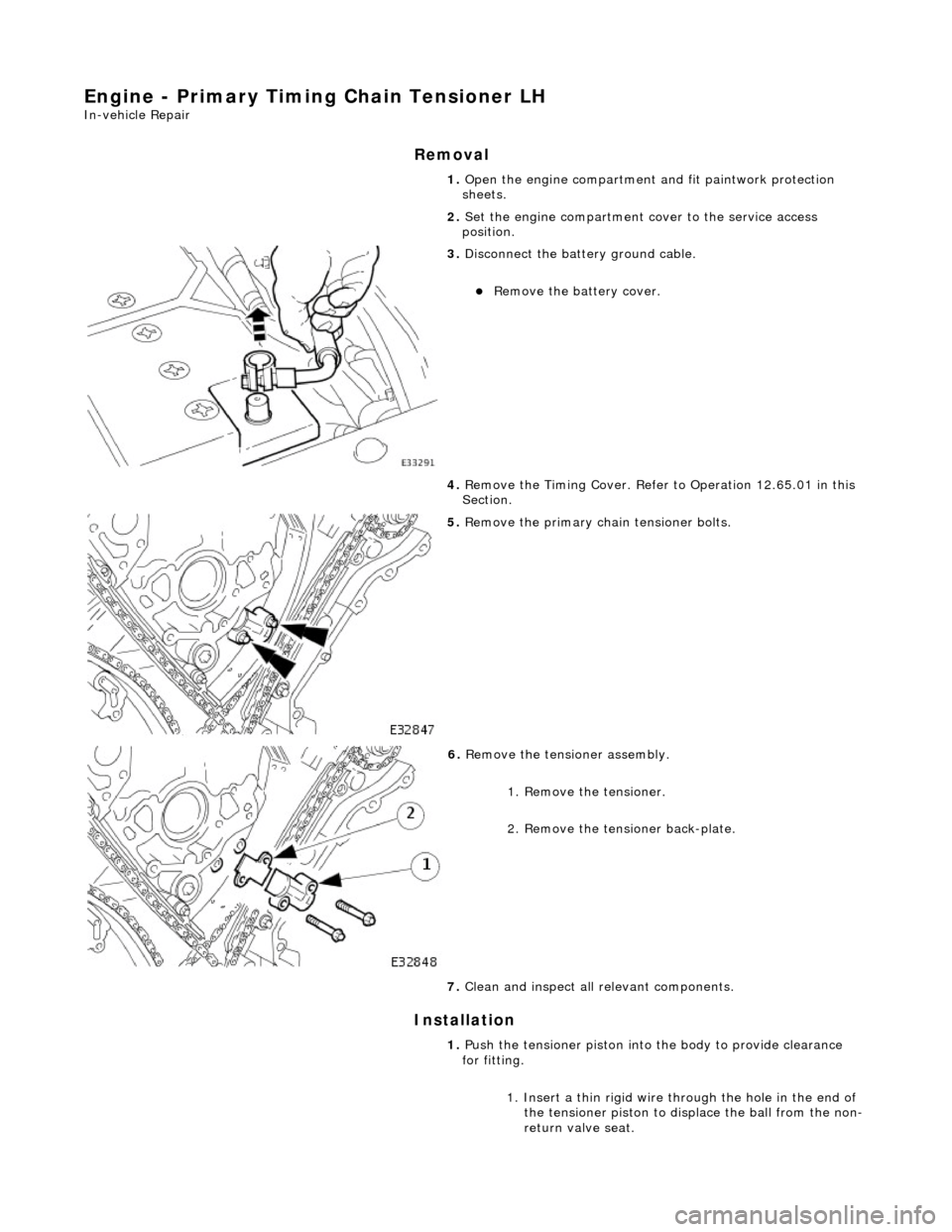
3. Disconnect the batt ery ground cable.
Remove the battery cover.
4. Remove the Timing Co ver. Refer to Operation 12.65.01 in this
Section.
5. Remove the primary ch ain tensioner bolts.
6. Remove the tensioner assembly.
1. Remove the tensioner.
2. Remove the tensioner back-plate.
7. Clean and inspect all relevant components.
1. Push the tensioner piston into the body to provide clearance
for fitting.
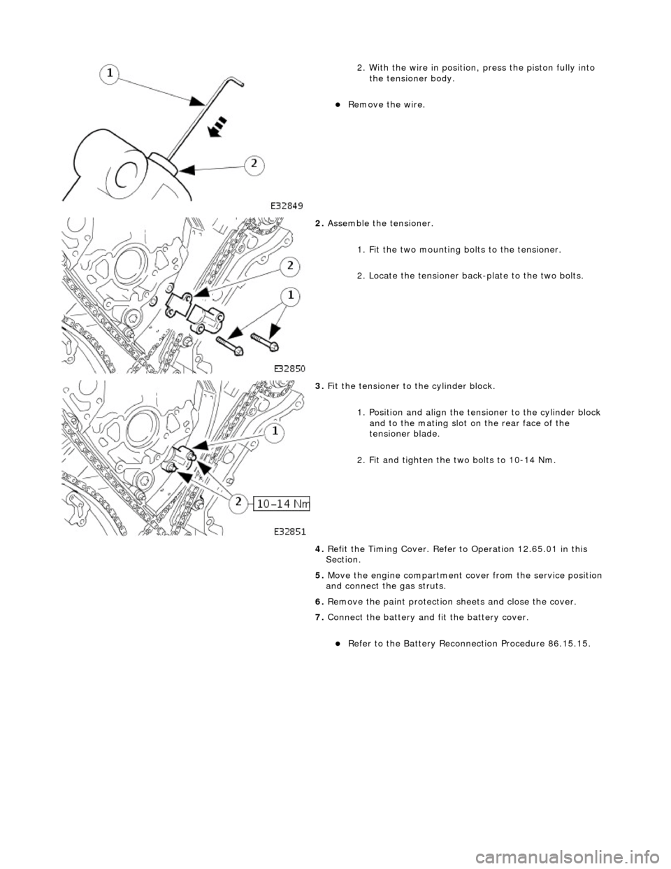
1. Insert a thin rigid wire th rough the hole in the end of
the tensioner piston to displace the ball from the non-
return valve seat.
Page 795 of 2490

2. With the wire in position, press the piston fully into the tensioner body.
Remove the wire.
2. Assemble the tensioner.
1. Fit the two mounting bolts to the tensioner.
2. Locate the tensioner back-plate to the two bolts.
3. Fit the tensioner to the cylinder block.
1. Position and align the tensioner to the cylinder block and to the mating slot on the rear face of the
tensioner blade.
2. Fit and tighten the two bolts to 10-14 Nm.
4. Refit the Timing Cover. Refer to Operation 12.65.01 in this
Section.
5. Move the engine compartment co ver from the service position
and connect the gas struts.
6. Remove the paint protection sheets and close the cover.
7. Connect the battery and fit the battery cover.
Refer to the Battery Reconnection Procedure 86.15.15.
Page 796 of 2490

Engine - Primary Timing Chain Tensioner RH
In-vehicle Repair
Removal
Installation
1. Open the engine compartment and fit paintwork protection
sheets.
2. Set the engine compartment cover to the service access
position.
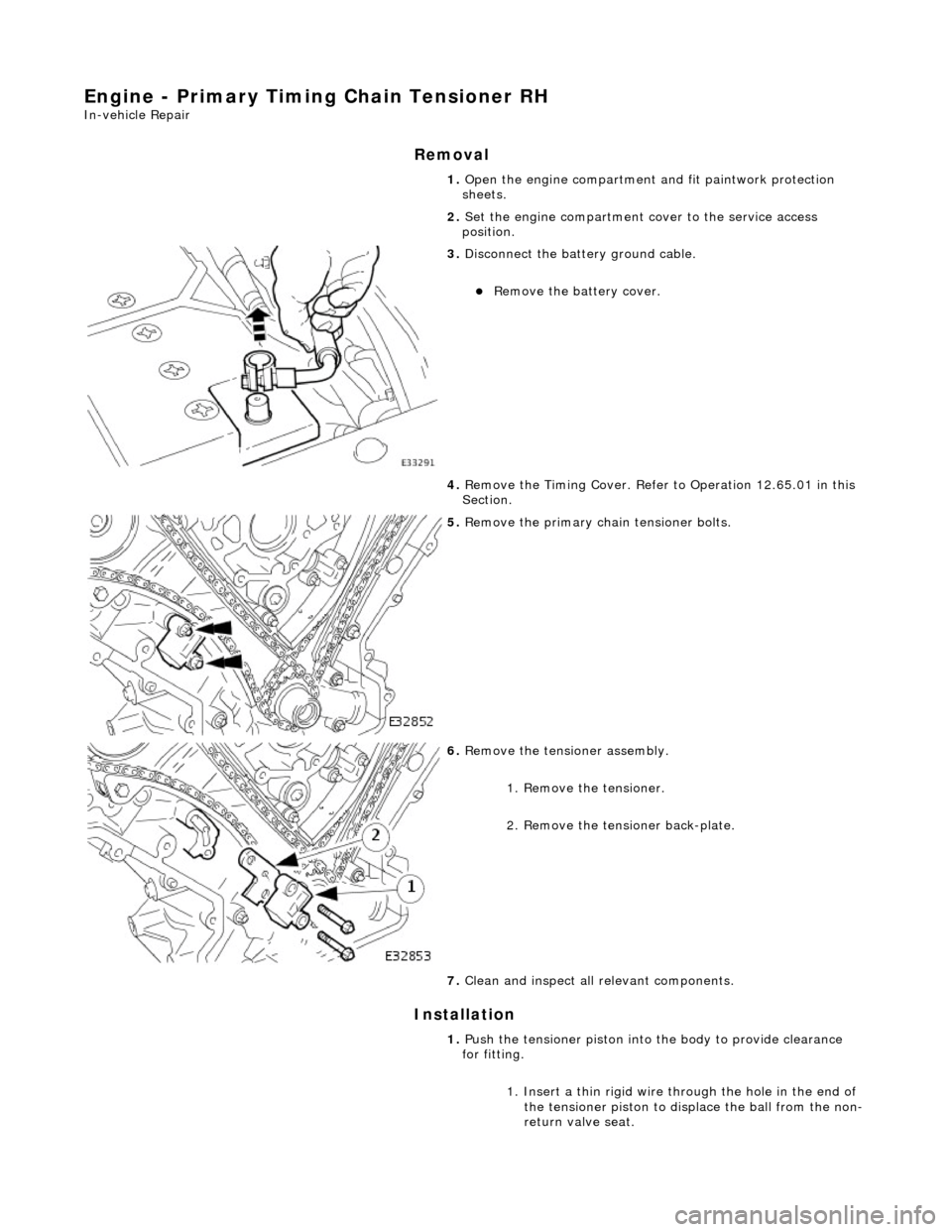
3. Disconnect the batt ery ground cable.
Remove the battery cover.
4. Remove the Timing Co ver. Refer to Operation 12.65.01 in this
Section.
5. Remove the primary ch ain tensioner bolts.
6. Remove the tensioner assembly.
1. Remove the tensioner.
2. Remove the tensioner back-plate.
7. Clean and inspect all relevant components.
1. Push the tensioner piston into the body to provide clearance
for fitting.
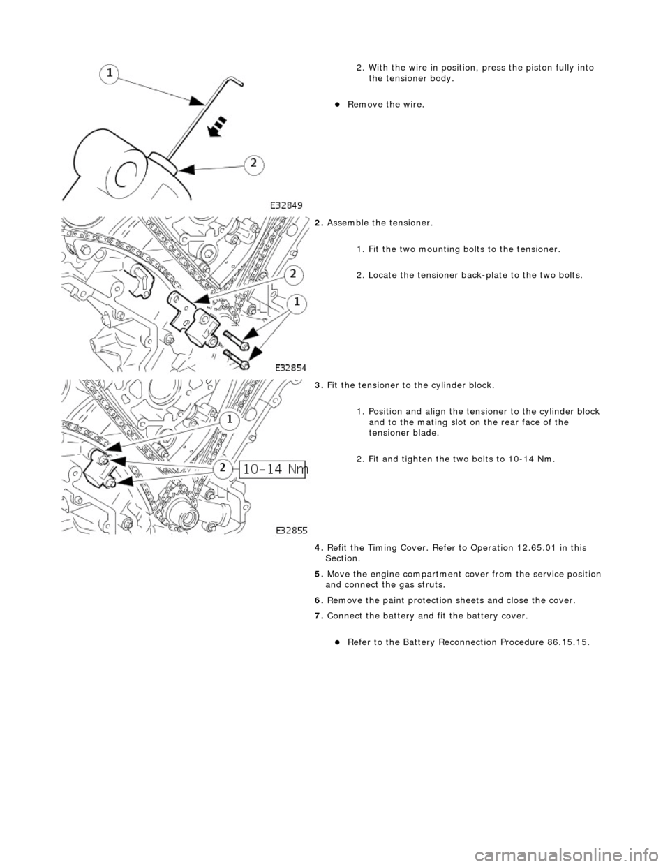
1. Insert a thin rigid wire th rough the hole in the end of
the tensioner piston to displace the ball from the non-
return valve seat.
Page 797 of 2490

2. With the wire in position, press the piston fully into the tensioner body.
Remove the wire.
2. Assemble the tensioner.
1. Fit the two mounting bolts to the tensioner.
2. Locate the tensioner back-plate to the two bolts.
3. Fit the tensioner to the cylinder block.
1. Position and align the tensioner to the cylinder block and to the mating slot on the rear face of the
tensioner blade.
2. Fit and tighten the two bolts to 10-14 Nm.
4. Refit the Timing Cover. Refer to Operation 12.65.01 in this
Section.
5. Move the engine compartment co ver from the service position
and connect the gas struts.
6. Remove the paint protection sheets and close the cover.
7. Connect the battery and fit the battery cover.
Refer to the Battery Reconnection Procedure 86.15.15.
Page 801 of 2490

Installation
20. Clean and inspect all relevant components.
1. Push the tensioner piston (secon dary chain) into the body to
provide clearance for fitting.
1. Insert a thin rigid wire th rough the hole in the end of
the tensioner piston to displace the ball from the non-
return valve seat.
2. With the wire in position, press the piston fully into the tensioner body.
Remove the wire.
2. Fit the VVT unit to the engine.
Assemble the VVT unit, the exhaust camshaft sprocket
and the secondary chain, in pr eparation for fitting to the
engine.
1. Fit the above assembly to the camshafts with the chain correctly positioned over the tensioner; VVT
unit to the inlet and the sprocket to the exhaust.
2. Fit, but do not tighten, each bolt which secures the VVT unit and the exhaust sprocket to the camshafts.
Allow the VVT unit sufficien t space to fit the primary
chain, in a la ter operation.
3. Fit the chain tensioning tool 303 - 532 to the exhaust camshaft
sprocket.
Reposition the sprocket (and the VVT unit) for the most
advantageous position for use of the tool.
Remove the tool.
4. Refit the primary timing chain.
1. Lift the primary chain an d position it over the VVT
unit sprocket (the VVT unit mu st be pulled forward to
clear the cylinder head casting). There must be no
slack on the drive side of the primary chain and the
VVT unit must not be rotated on the camshaft.
2. Slide the VVT unit fully on to the camshaft.
5. Fit the primary chain tensioner blade.
1. Position the tensioner blade to the cylinder block.
Page 806 of 2490

Installation
15. Remove the primary ch ain tensioner blade.
1. Remove the pivot bolt which secures the tensioner blade.
2. Remove the tensioner blade.
16. Disconnect the primary chain from the VVT unit and the
crankshaft sprocket, and remove it completely.
17. Do not tamper with the three bolts which secure the VVT
mechanism to the sprockets. It is sealed at the factory to the
correct valve timing specificatio n for the engine and is supplied
only as a complete unit.
18. Remove the VVT unit.
1. Remove the securing bolt from both the VVT unit and
the exhaust cam sprocket.
2. Remove the VVT unit, exhaust sprocket and secondary chain as an asse mbly (release the chain
from the tensioner which is still secured to the
cylinder head).
Remove the secondary chain from the VVT unit and the
sprocket.
19. Clean and inspect all relevant components.
1. Push the tensioner piston (secon dary chain) into the body to
provide clearance for fitting.
1. Insert a thin rigid wire th rough the hole in the end of
the tensioner piston to displace the ball from the non-
return valve seat.
2. With the wire in position, press the piston fully into the tensioner body.
Remove the wire.
2. Fit the VVT unit to the engine.
Assemble the VVT unit, the exhaust camshaft sprocket
and the secondary chain, in pr eparation for fitting to the
engine.
1. Fit the above assembly to the camshafts with the chain correctly positioned over the tensioner; VVT
unit to the inlet and the sprocket to the exhaust.
2. Fit, but do not tighten, each bolt which secures the VVT unit and the exhaust sprocket to the camshafts.
Page 812 of 2490

Installation
12. Remove the bolt which secures the sprocket to the exhaust
camshaft.
Move the sprocket forward from the camshaft boss.
13. Remove the secondary chain tensioner.
1. Remove the two bolts which secure the tensioner.
Lift the tensioner, sprocket (release it fully from the
camshaft) and ch ain assembly.
2. Remove the tensioner rearward from between the chain.
14. Remove the sprocket if required, or leave it in the chain
resting on the cylinder head.
15. Clean and inspect all relevant components.
1. Install the sprocket to the secondary chain.
1. With the sprocket installe d to the chain, temporarily
position (do not install the securing bolt) the sprocket
onto the camshaft.
2. Adjust the position of the sprocket within the chain to
allow the chain tensioning tool 303-532 to be
approximately vertical, as shown.
Remove the chain tensioni ng tool; during future
operations, do not move the sprocket within the chain.
2. Push the tensioner piston into the body to provide clearance
for installing.
1. Insert a thin rigid wire th rough the hole in the end of
the tensioner piston to displace the ball from the non-
return valve seat.
Page 813 of 2490

2. With the wire in position, press the piston fully into the tensioner body.
Remove the wire.
3. Install the chain tensioner between the chain path.
1. Reposition the sprocket, still captive in the chain, upwards for access.
2. Install the chain tensioner between the sprockets.
Position the cam sprocket, chain and tensioner assembly
into position and locate the sprocket onto the camshaft
spigot.
4. Install the chain tensioner to the engine.
1. Fully seat the sprocket onto the camshaft and install the securing bolt, hand tight.
2. Install the two bolts which secure the tensioner and tighten to 10-14 Nm.
5. Install the cams haft sprocket.
Install the chain tensioner tool 303-532 to the sprocket
holes.
Apply force to the tool in an anti-clockwise direction to
tension the chain on its drive side.
Whilst applying the opposing force to the sprocket and
chain, tighten the sprocket securing bolt to 115-125 Nm.
Remove the chain tensioning tool.
6. Remove the tape and steel stri p from the timing cover upper
face. Wipe any residue of tape from the joint face.
7. Remove the camshaft locking tool.
8. Install the Cam Cover to Bank 2. Refer to Operation 12.29.43.
9. Raise the vehicle on the ramp.
10. Remove the crankshaft setting tool 303-531.