engine ignition JAGUAR X308 1998 2.G Workshop Manual
[x] Cancel search | Manufacturer: JAGUAR, Model Year: 1998, Model line: X308, Model: JAGUAR X308 1998 2.GPages: 2490, PDF Size: 69.81 MB
Page 1535 of 2490
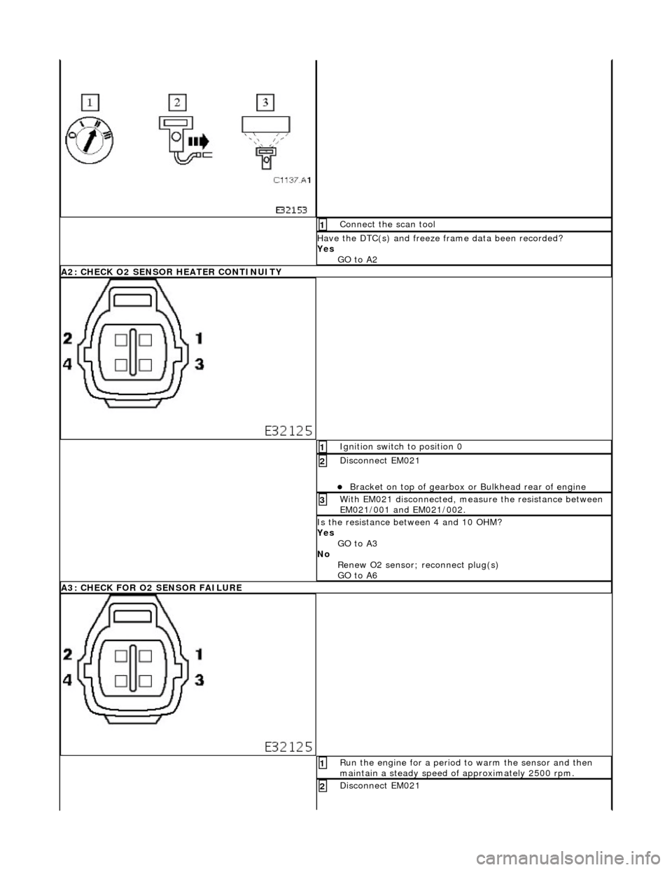
Connect the scan tool 1
Have the DTC(s) and freeze frame data been recorded?
Yes GO to A2
A2: CHECK O2 SENSOR HEATER CONTINUITY
Ignition switch to position 0 1
Disconnect EM021
Bracket on top of gearbox or Bulkhead rear of engine
2
With EM021 disconnected, measure the resistance between
EM021/001 and EM021/002. 3
Is the resistance between 4 and 10 OHM?
Yes
GO to A3
No Renew O2 sensor; reconnect plug(s)
GO to A6
A3: CHECK FOR O2 SENSOR FAILURE
Run the engine for a period to warm the sensor and then
maintain a steady speed of approximately 2500 rpm. 1
Disconnect EM021 2
Page 1546 of 2490
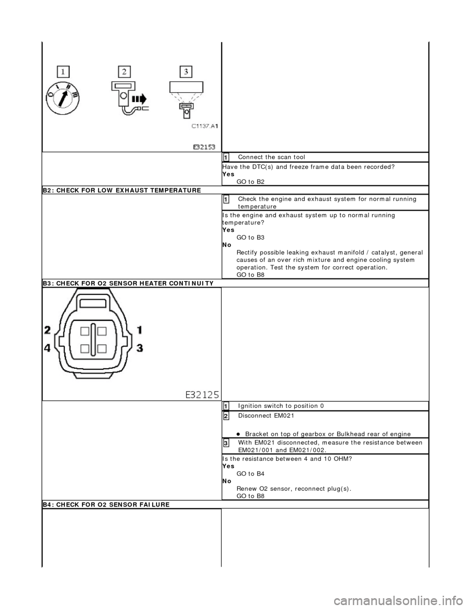
Connect the scan tool 1
Have the DTC(s) and freeze frame data been recorded?
Yes GO to B2
B2: CHECK FOR LOW EX HAUST TEMPERATURE
Check the engine and exhaust system for normal running
temperature 1
Is the engine and exhaust sy stem up to normal running
temperature?
Yes GO to B3
No Rectify possible leaking exhaust manifold / catalyst, general
causes of an over rich mixture and engine cooling system
operation. Test the system for correct operation.
GO to B8
B3: CHECK FOR O2 SENS OR HEATER CONTINUITY
Ignition switch to position 0 1
Disconnect EM021
Bracket on top of gearbox or Bulkhead rear of engine
2
With EM021 disconnected, measure the resistance between
EM021/001 and EM021/002. 3
Is the resistance between 4 and 10 OHM?
Yes
GO to B4
No Renew O2 sensor, reconnect plug(s).
GO to B8
B4: CHECK FOR O2 SENSOR FAILURE
Page 1558 of 2490
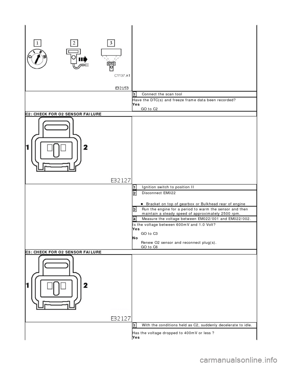
Connect the scan tool 1
Have the DTC(s) and freeze frame data been recorded?
Yes GO to C2
C2: CHECK FOR O2 SENSOR FAILURE
Ignition switch to position II 1
Disconnect EM022
Bracket on top of gearbox or Bulkhead rear of engine
2
Run the engine for a period to warm the sensor and then
maintain a steady speed of approximately 2500 rpm. 3
Measure the voltage between EM022/001 and EM022/002. 4
Is the voltage between 600mV and 1.0 Volt?
Yes
GO to C3
No Renew O2 sensor and reconnect plug(s).
GO to C6
C3: CHECK FOR O2 SENSOR FAILURE
With the conditions held as C2, suddenly decelerate to idle. 1
Has the voltage dropped to 400mV or less ?
Yes
Page 1585 of 2490
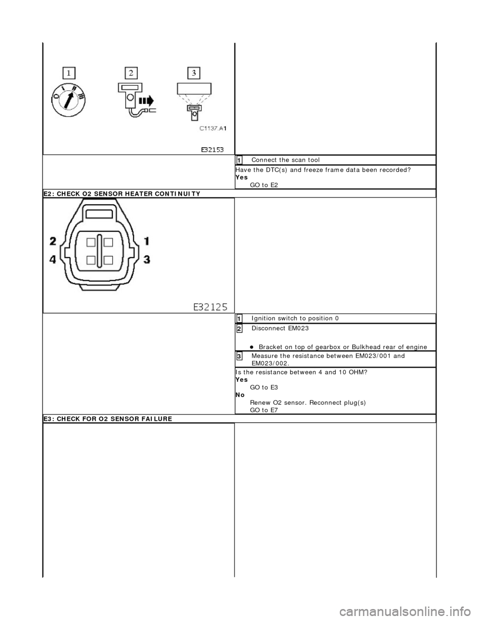
Connect the scan tool 1
Have the DTC(s) and freeze frame data been recorded?
Yes GO to E2
E2: CHECK O2 SENSOR HEATER CONTINUITY
Ignition switch to position 0 1
Disconnect EM023
Bracket on top of gearbox or Bulkhead rear of engine
2
Measure the resistance between EM023/001 and
EM023/002. 3
Is the resistance between 4 and 10 OHM?
Yes
GO to E3
No Renew O2 sensor. Reconnect plug(s)
GO to E7
E3: CHECK FOR O2 SENSOR FAILURE
Page 1598 of 2490
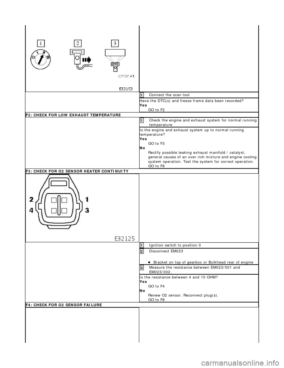
Connect the scan tool 1
Have the DTC(s) and freeze frame data been recorded?
Yes GO to F2
F2: CHECK FOR LOW EXHAUST TEMPERATURE
Check the engine and exhaust system for normal running
temperature 1
Is the engine and exhaust sy stem up to normal running
temperature?
Yes GO to F3
No Rectify possible leaking exhaust manifold / catalyst,
general causes of an over ri ch mixture and engine cooling
system operation. Test the sy stem for correct operation.
GO to F8
F3: CHECK FOR O2 SENSOR HEATER CONTINUITY
Ignition switch to position 0 1
Disconnect EM023
Bracket on top of gearbox or Bulkhead rear of engine
2
Measure the resistance between EM023/001 and
EM023/002. 3
Is the resistance between 4 and 10 OHM?
Yes
GO to F4
No Renew O2 sensor. Reconnect plug(s).
GO to F8
F4: CHECK FOR O2 SENSOR FAILURE
Page 1690 of 2490
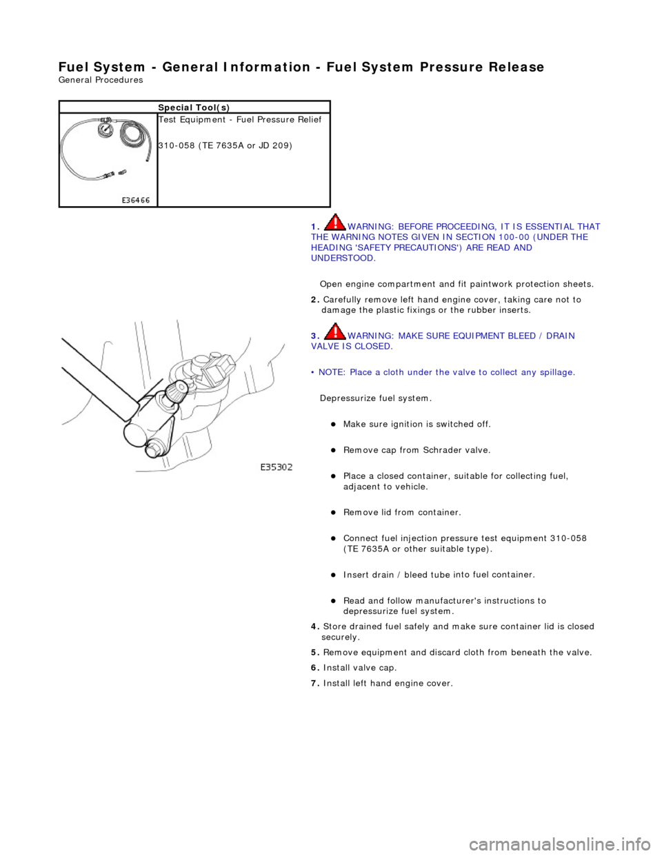
Fuel System - General Information - Fuel System Pressure Rele
ase
Gen
e
ral Procedures
S p
ecial Tool(s)
Tes
t
Equipment - Fuel Pressure Relief
310-058 (TE 7635A or JD 209)
1. WARNING: BEFORE PROCEEDING, IT IS ESSENTIAL THAT
THE WARNING NOTES GIVEN IN SECTION 100-00 (UNDER THE
HEADING 'SAFETY PRECAUTIONS') ARE READ AND
UNDERSTOOD.
Open engine compartment and fi t paintwork protection sheets.
2. Carefull
y remove left
hand engine cover, taking care not to
damage the plasti c fixings or the rubber inserts.
3. WA
RNING: MAKE SURE EQUIPMENT BLEED / DRAIN
VALVE IS CLOSED.
• NOTE: Place a cloth under the valve to collect any spillage.
Depressurize fuel system.
Make sure ignition i s
switched off.
R
e
move cap from Schrader valve.
Pla
c
e a closed container, su
itable for collecting fuel,
adjacent to vehicle.
R e
move lid from container.
Conne
ct
fuel injection pressu
re test equipment 310-058
(TE 7635A or other suitable type).
Insert drain / bleed tu be i
nto fuel container.
R
e
ad and follow manufacturer's instructions to
depressurize fuel system.
4. Store drained f u
el safely and make
sure container lid is closed
securely.
5. Remove equipment and discard cloth from beneath the valve.
6. Install valve cap.
7. Install left hand engine cover.
Page 1691 of 2490
Fuel System - Gener
al Information - Fuel Tank Draining
Gen
eral Procedures
1.
WARNING: BEFORE PROCEEDING, IT IS ESSENTIAL THAT
THE WARNING NOTES GIVEN IN SECTION 100-00 (UNDER THE
HEADING 'SAFETY PRECAUTIONS') ARE READ AND
UNDERSTOOD.
Remove the battery. Refer to operation 86.15.01.
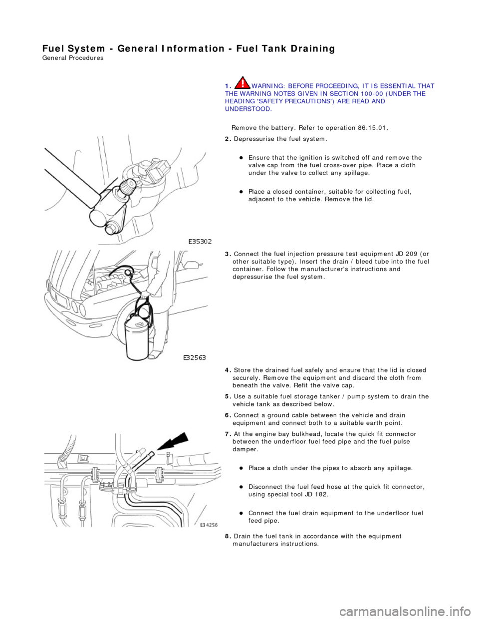
2. De
pressurise the fuel system.
E
nsure that the ignition is
switched off and remove the
valve cap from the fuel cross-over pipe. Place a cloth
under the valve to collect any spillage.
Pla
ce a closed container, su
itable for collecting fuel,
adjacent to the vehicle. Remove the lid.
3. Conne
ct the fuel injection pressu
re test equipment JD 209 (or
other suitable type). Insert the drain / bleed tube into the fuel
container. Follow the manufa cturer's instructions and
depressurise the fuel system.
4. Store the drained fuel safely and ensure that the lid is closed
securely. Remove the equipmen t and discard the cloth from
beneath the valve. Refit the valve cap.
5. Use a suitable fuel storage tank er / pump system to drain the
vehicle tank as described below.
6. Connect a ground cable betw een the vehicle and drain
equipment and connect both to a suitable earth point.
7. At the engine bay bulkhead, lo cate the quick fit connecto
r
between the underfloor fuel feed pipe and the fuel pulse
damper.
Pla
ce a cloth under the pipes
to absorb any spillage.
D
isconnect the fuel feed hose
at the quick fit connector,
using special tool JD 182.
Conne
ct the fuel drain equipment to the underfloor fuel
feed pipe.
8. Drain the fuel tank in accordance with the equipment
manufacturers instructions.
Page 1743 of 2490
Accelerati
on Control - Accelerator Cable Adjustment
Gen
eral Procedures
1.
Load the Approved Jaguar Diagno stic System with power train
data logger.
2. Connect the Approved Jaguar Diag nostic System to the vehicle.
3. W
ith 'Disable Network Integrity Test - YES/ NO' displayed on
the screen select YES.
4. With new menu displayed on the screen, select ' Engine
Management'.
5. Turn the ignition to ON.
R
emove any previously selected data logger parameters.
6. On data logger select PPS11 an d PPS2 (Pedal demand sensors
1 and 2).
7. On Sedan models only, remove the bulkhead covers on both
sides and the engine compartment rear cover.
8. Cut, remove and discard the ra tchet strap which retains the
throttle cable to the abutment bracket.
9. Ensure there is no tension on the throttle cable by releasing
the throttle cable adjustment nut from the abutment bracket.
10. Record the voltages for both sensors, PPS11 and PPS2.
11. Partially insert the throttle cable adjustment nut into the
abutment bracket.
12. Recheck the voltages for both sensors, PPS11 and PPS2.
13. Where the voltages at step 12 are higher than the voltages
taken at step 10, contin ue to step 15 below.
14. Where the voltages at step 12 are the same as the voltages
taken at step 10, contin ue to step 16 below.
15. Rotate the adjustment nut clockwise (as viewed from the
front of the vehicle) until the same voltages are indicated as in
step 10. Continue to turn thro ugh a part revolution until the
sides of the nut are vertical. Tu rn through a further 90 degrees,
then fully insert the nut into the abutment bracket.
16. Rotate the adjustment nut anti-clockwise (as viewed from the
front of the vehicle) until the indicated voltage starts to
increase. Then rotate the nut clockwise through a part
revolution until the sides are ve rtical. Turn through a further 90
degrees, then fully insert the nut into the abutment bracket.
17. Fit a new ratchet strap to secure the throttle cable adjusting
nut to the abutment bracket.
18. Operate the throttle pedal through 20 full cycles to settle the
cable. Check the voltages now shown, remain the same as in
steps 15 and 16.
19. Check and where necessary adjust the kickdown switch. For
additional information, refer to Section 307
-05A Automatic Transmissi
on/Transaxle External Controls
Sectio
n
307
-05
B
Au
tomatic Transmission/Tra
nsaxle External Controls
.
20
.
On Sedan models only, refit the engine compartment rear
cover and the bulkhead co vers on both sides.
21. Switch the ignition OFF and disconnect the Approved Jaguar
Diagnostic System.
Page 1785 of 2490
Engine speed (valve closed with the engine not running) Demand (set) temperature In-car temperature sensor Solar sensor
Re-heating of the refrigerated air is contro lled by the time that the water valve is open (i.e. not energised) over a six secon d
interval. The duty cycle of the water valve, the time open / time closed, is controlled by the A/CCM.
Maximum heating demand will cause the water valve to be fu lly open (not energised) to allow maximum coolant flow
through the heater matrix.
At Maximum cooling, the water va lve will be fully closed (energised) to prevent hot (engine temperature) coolant entering
the heater circuit; the pump however will continue to circulate coolant through both the heater matrix and water valve
bypass.
The water valve defaults open when the ignition is OFF.
Under engine stall conditions, when ignition is ON, the water valve will be open.
Water Pump Assembly
Located in the same area as the water valve, the water pump continually circulates coolant through the heater matrix
except when the conditions below apply:
The engine coolant is below 16°C. The ignition is OFF. Under engine stall conditions, when ignition is ON. Control panel OFF
Non return valves
The heater bypass hose has a non-return valve, located between the engine feed and return hoses. The valve prevents the
water pump from recirculating coolant fro m the heater at low engine speeds.
The flow indicator arrow embossed on the valve bo dy MUST point towards the coolant header tank.
CAUTION: Coolant flow will be compromi sed if either valve is fitted incorrectly. Observe the correct direction.
A second non-return valve is located betw een the water pump and water valve. This valve prevents hot coolant from flowing
into the heater with the engine switched off. The flow indicator arrow MUST point towards the water pump.
Heater feed and return hoses
The heater feed and return hoses are connected to the engine feed and return hoses by 'Quick-Fit' connection unions. The
feed hose has a Norma R20 connector and the return hose a Norma push and seal connector. The coolant system bleed
joints have Cobra clamps. All remaining hose connections have spring band hose clamps.
The engine feed hose is connected to the engine bypass hous ing and the engine return hose is connected to the engine
water pump.
Clamp Identification
Page 1823 of 2490
8.8. Automatic
Symbol indicates when the control of , temperature, fan speed and air distribution are all in Auto mode.
9. 9. External
There are two modes of external ambient temperature selection;
Quick Display. Pressing the button for <1.5 seconds (con firmed by a single bleep) will display the external
temperature for 4 seconds.
Continuous Display. Pressing and holding the button fo r >1.5 seconds (confirmed by two beeps) displays the
external ambient temperature continuously, the value of which will be updated every 4 seconds given that vehicle
road speed is > 25 km/h. Pressing the button again fo r <1.5 seconds resets to the previous display.
• NOTE: Continuous external temperature display will be cancel led when the ignition is switched OFF but not during engine
cranking.
10. 10. A/C
This push-on / push-off button will either select or deselect (as indicated by the state lamp) the refrigeration system.
The refrigeration system is automatically engaged when the Auto button is pressed.
• NOTE: Interior misting of screens may be reduced by continuous operation of th e refrigeration system.
11. 11. Auto
When selected and the state lamp lit, A/C mode will be operat ional and control of vent outlet temperature, fans speed and
air distribution will be automatic.
AUTO mode will disengage should manual air distribution or defrost buttons be operated or the manual fan speed knob be
rotated.
• NOTE: Automatic temperature control is constantly main tained irrespective of selected manual overrides.
12. 12. Defrost
Push-on push-off button, which when engaged will direct all air to the front and side glass at maximum fan speed. The
heated windshield (if fitted) will also be energized for a timed cycle of 6,5 minute s, but may be cancelled by pressing the
HEATED WINDSHIELD (F) button. Pressing 'DEF' again will retu rn to the last setting with automatic temperature control
being maintained.
Directing warm and humid air onto a cold screen can produce interior misting of screens. Operating the climate control
system without the refrigerati on system operating will exacerbate this problem.
• NOTE: Directing cold air onto the screen in warm humid conditions can produce external condensation.
13. 13. Heated Windshield (F)
Pressing the heated windshield button (whe re fitted) will energize the electrically heated windshield elements for a timed
cycle of 6,5 minutes; pressing the button again will cancel the request. Should the engine stall or the ignition be turned
OFF, the timer will be cleare d and the function cancelled.
• NOTE: The heated windshield may be activated with the cl imate control system OFF but the engine must be running.
In very cold ambient temperatures, icing of the interior of the glass is possible when the climate control system is operating
in AUTO mode; to reduce this poss ibility the A/CCM provides automatic operation of the heated windshield.
With the following conditions met, the heated windshield will automatically energize but the state lamp will NOT be lit.