DTC JAGUAR X308 1998 2.G Workshop Manual
[x] Cancel search | Manufacturer: JAGUAR, Model Year: 1998, Model line: X308, Model: JAGUAR X308 1998 2.GPages: 2490, PDF Size: 69.81 MB
Page 1322 of 2490

Connect the scan tool 1
Have the DTC(s) and freeze frame data been recorded?
Yes GO to I2
I2: CHECK HARNESS +VE CONTIN UITY (INPUT SPEED SENSOR)
With EM007 and EM046 disconnected, measure the resistance between EM046/005 and EM007/042 1
Is the resistance < 0.5 OHM?
Yes
Reconnect EM046
GO to I3
No Inspect harness / connectors EM007 and EM046 for damage,
corrosion, bent / pushed back pins. Repair as necessary and
test the system for normal operation.
I3: CHECK HARNESS -VE CONTINUITY (INPUT SPEED SENSOR)
Page 1330 of 2490

Pinpoint test J: P1603, P1605, P1608
With EM007 and EM046 disconnected, measure the insulation
resistance between EM007/016 and EM007/044 1
Repeat for EM007/014 and EM007/042 2
Is the resistance > 10 MOHM?
Yes GO to I11
No Inspect harness / connectors EM007 and EM046 for damage,
corrosion, bent / pushed back pins. Repair as necessary and
test the system for normal operation.
I11: END
Perform appropriate service drive cycle and check for the
presence of DTC 1
Has the fault code cleared?
Yes STOP
No Contact Jaguar Service
PINPOINT TEST J : P1603, P1605, P1608
• NOTE: It is important that J3 item 1 is carried out in order that system adaptions take place
TEST CONDITIONSDETAILS/RESULTS/ACTIONS
J1: RETRIEVE DTCS
• NOTE: Following ECM power-down, the DTC will be lost and may only be disp layed when the ignition is energized
Page 1331 of 2490
Pinpoint test K: P1789, P1793
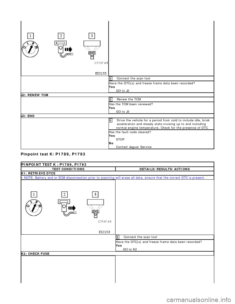
Connect the scan tool 1
Have the DTC(s) and freeze frame data been recorded?
Yes GO to J2
J2: RENEW TCM
Renew the TCM 1
Has the TCM been renewed?
Yes GO to J3
J3: END
Drive the vehicle for a period from cold to include idle, brisk
acceleration and steady state cruising up to and including
normal engine temperature. Check for the presence of DTC 1
Has the fault code cleared?
Yes STOP
No Contact Jaguar Service
PINPOINT TEST K : P1789, P1793
TEST CONDITIONSDETAILS/RESULTS/ACTIONS
K1: RETRIEVE DTCS
• NOTE: Battery and or ECM disconnection prior to scanning wi ll erase all data, ensure that the correct DTC is present.
Connect the scan tool 1
Have the DTC(s) and freeze frame data been recorded?
Yes GO to K2
K2: CHECK FUSE
Page 1333 of 2490

Pinpoint test L: P0710
With EM007 and LS008 disconnected, measure the
resistance between EM007/054 and LS008/007 1
Repeat for EM007/055 and LS008/007 2
Is the resistance < 0.5 OHM?
Yes GO to K5
No Inspect harness / connector EM007, LS008, EM051, splice
EMS42 for damage, corrosion, bent / pushed back pins.
Repair as necessary and te st the system for normal
operation.
K5: END
Perform appropriate service drive cycle and check for the
presence of DTC. 1
Has the fault code cleared?
Yes STOP
No Contact Jaguar Service
PINPOINT TEST L : P0710
TEST CONDITIONSDETAILS/RESULTS/ACTIONS
L1: RETRIEVE DTCS
• NOTE: Battery and or ECM disconnection prior to scanning wi ll erase all data, ensure that the correct DTC is present.
Page 1334 of 2490
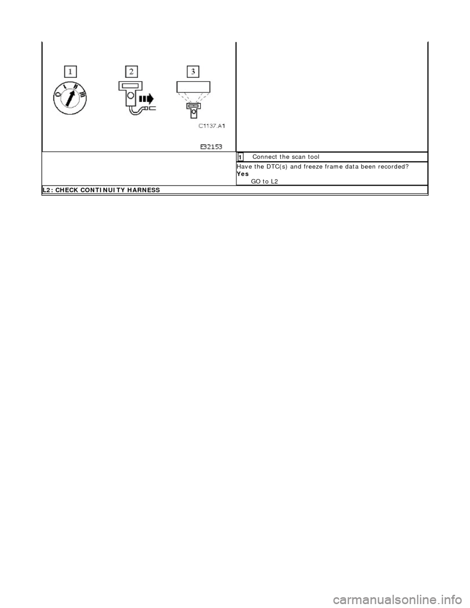
Connect the scan tool 1
Have the DTC(s) and freeze frame data been recorded?
Yes GO to L2
L2: CHECK CONTINUITY HARNESS
Page 1391 of 2490
In the event of a system fault, the TCM will adopt 'limp home' mode.
Electrical control
Refer to Section 307-01B.
Transmission Control Components
Transmission Control Module (TCM)
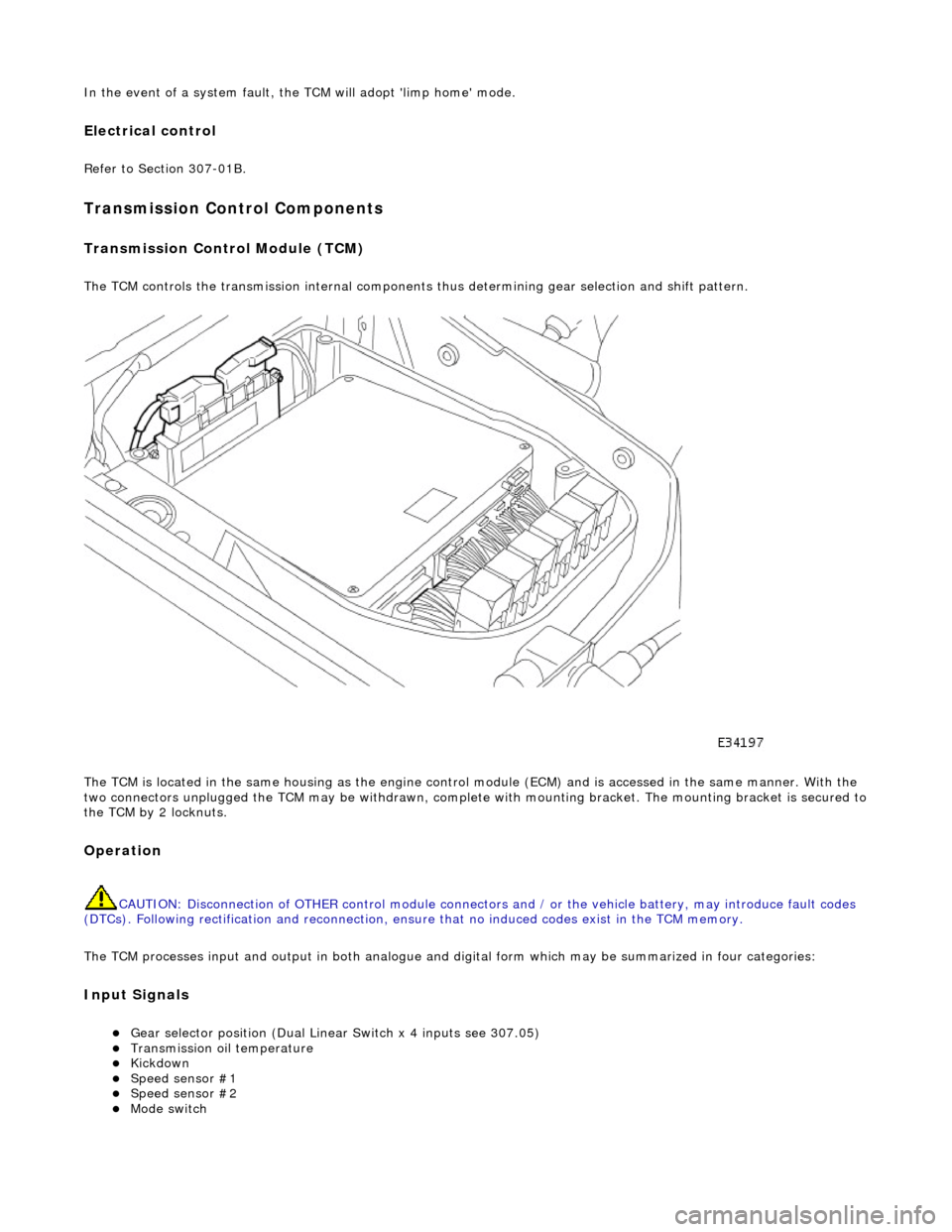
The TCM controls the transmission internal components thus determining gear selection and shift pattern.
The TCM is located in the same housing as the engine control module (ECM) and is accessed in the same manner. With the
two connectors unplugged the TCM may be withdrawn, complete with mounting bracket. The mounting bracket is secured to
the TCM by 2 locknuts.
Operation
CAUTION: Disconnection of OTHER contro l module connectors and / or the vehicle battery, may introduce fault codes
(DTCs). Following rectification and reconnection, ensu re that no induced codes exist in the TCM memory.
The TCM processes input and output in both analogue and di gital form which may be summarized in four categories:
Input Signals
Gear selector position (Dual Linear Switch x 4 inputs see 307.05) Transmission oil temperature Kickdown Speed sensor #1 Speed sensor #2 Mode switch
Page 1392 of 2490
CAN Input Signals
Traction status ABS malfunction ABS status Engine torque status Throttle position Accelerator pedal position Engine torque reduction confirmation Engine speed Engine coolant temperature Cruise status OBDII fault code clear request Throttle malfunction warning RED or AMBER All road wheel speeds Token for network status ECM Token for network status INST Token for network status ABS Diagnostic data in from external device (PDU)
Output Signals
Solenoid valve 1 <-> 2 and 4 <-> 5 shift Solenoid valve 2 <-> 3 shift Solenoid valve 3 <-> 4 shift Solenoid valve converter lock-up clutch Control valve - modulating pressure Control valve - shift pressure
CAN Output Signals
Engine torque reduction request MIL status (whether present DTC should operate MIL) Transmission input speed Transmission output speed Converter slip Kickdown status Gear position (actual) Gear position (selected) Gear selection fault Converter lock-up status Current selected shift map Transmission oil temperature Transmission malfunction Pecus flag (state of current TCM program) Target for next gear position Gear shift torque transfer progress at shift MIL status (response to activate the MIL relevant to a DTC) OBDII fault code clear acknowledgement Transmission DTCs (P codes) Token for network status TCM Diagnostic data out to external device (PDU)
Emergency Running (elect ronic limp-home mode)
The TCM constantly monitors the transmissi on for faults. In the event of a problem the TCM will adopt the limp-home mode, in which the gear currently held remains engaged, until P is selected. The modulati ng and shift pressures will increase to
maximum and converter lock-up will be inhibited.
Following the selection of P , the only ratios available will be 2 (irrespective of forward ratio manual selection) and R .
With the vehicle at rest, the procedure to manually select is as follows:
1. 1. Select P .
Page 1400 of 2490
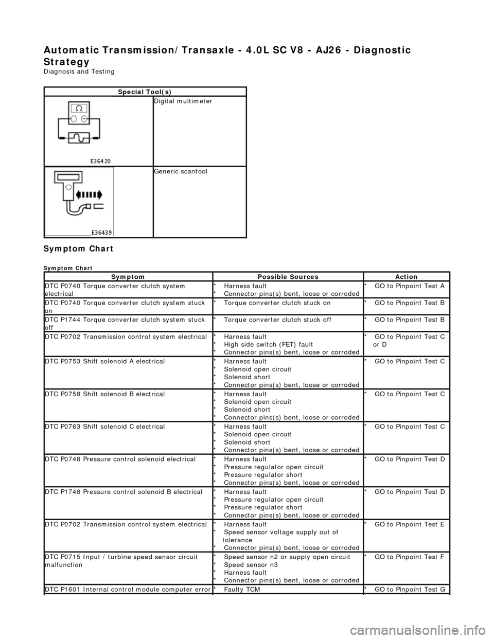
Automatic Transmission/Transaxle - 4.0L SC V8 - AJ26 - Diagnostic
Strategy
Diagnosis and Testing
Symptom Chart
Symptom Chart
Special Tool(s)
Digital multimeter
Generic scantool
SymptomPossible SourcesAction
DTC P0740 Torque converter clutch system
electricalHarness fault
Connector pins(s) bent , loose or corroded
*
*GO to Pinpoint Test A
*
DTC P0740 Torque converter clutch system stuck
onTorque converter clutch stuck on
*GO to Pinpoint Test B
*
DTC P1744 Torque converter clutch system stuck
offTorque converter clutch stuck off
*GO to Pinpoint Test B
*
DTC P0702 Transmission control system electricalHarness fault
High side switch (FET) fault
Connector pins(s) bent , loose or corroded
*
*
*GO to Pinpoint Test C
or D
*
DTC P0753 Shift solenoid A electricalHarness fault
Solenoid open circuit
Solenoid short
Connector pins(s) bent
, loose or corroded
*
*
*
*GO to Pinpoint Test C *
DTC P0758 Shift solenoid B electricalHarness fault
Solenoid open circuit
Solenoid short
Connector pins(s) bent
, loose or corroded
*
*
*
*GO to Pinpoint Test C *
DTC P0763 Shift solenoid C electricalHarness fault
Solenoid open circuit
Solenoid short
Connector pins(s) bent
, loose or corroded
*
*
*
*GO to Pinpoint Test C *
DTC P0748 Pressure control solenoid electricalHarness fault
Pressure regulator open circuit
Pressure regulator short
Connector pins(s) bent
, loose or corroded
*
*
*
*GO to Pinpoint Test D *
DTC P1748 Pressure control solenoid B electricalHarness fault
Pressure regulator open circuit
Pressure regulator short
Connector pins(s) bent
, loose or corroded
*
*
*
*GO to Pinpoint Test D *
DTC P0702 Transmission control system electricalHarness fault
Speed sensor voltage supply out of
tolerance Connector pins(s) bent , loose or corroded
*
*
*GO to Pinpoint Test E
*
DTC P0715 Input / turbine speed sensor circuit
malfunctionSpeed sensor n2 or supply open circuit
Speed sensor n3
Harness fault
Connector pins(s) bent , loose or corroded
*
*
*
*GO to Pinpoint Test F
*
DTC P1601 Internal control module computer errorFaulty TCM
*GO to Pinpoint Test G *
Page 1401 of 2490

Pinpoint test A: P0740
DTC P0730 Incorrect gear ratioEngaged gear implausible / transmission
slipping Oil level low
Valve body assembly faulty
Transmission faulty
*
*
*
*GO to Pinpoint Test H *
DTC P0780 Shift malfunctionValve body assembly faulty
Transmission faulty
*
*GO to Pinpoint Test H *
PINPOINT TEST A : P0740
TEST CONDITIONSDETAILS/RESULTS/ACTIONS
A1: RETRIEVE DTCS
• NOTE: Battery and or ECM disconnection prior to scanning wi
ll erase all data, ensure that the correct DTC is present.
Connect the scan tool 1
Have the DTC(s) and freeze frame data been recorded?
Yes GO to A2
A2: CHECK TORQUE CONVERTER CLUTCH SOLENOID RESISTANCE
With, EM062 disconnected, measure the resistance between 1
Page 1404 of 2490
Pinpoint test B: P0740, P1744
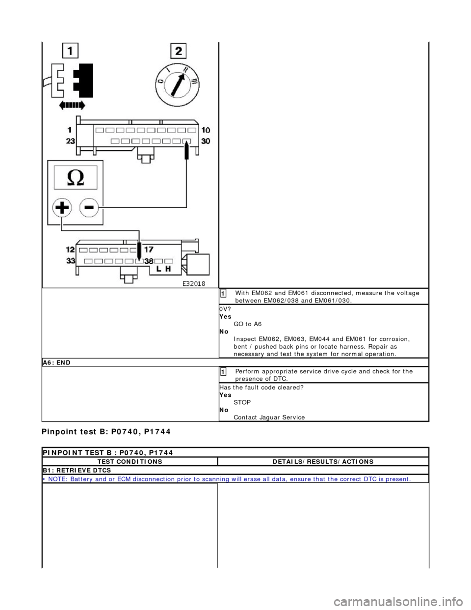
With EM062 and EM061 disconnected, measure the voltage
between EM062/038 and EM061/030. 1
0V?
Yes GO to A6
No Inspect EM062, EM063, EM044 and EM061 for corrosion,
bent / pushed back pins or locate harness. Repair as
necessary and test the syst em for normal operation.
A6: END
Perform appropriate service drive cycle and check for the
presence of DTC. 1
Has the fault code cleared?
Yes
STOP
No Contact Jaguar Service
PINPOINT TEST B : P0740, P1744
TEST CONDITIONSDETAILS/RESULTS/ACTIONS
B1: RETRIEVE DTCS
• NOTE: Battery and or ECM disconnection prior to scanning wi ll erase all data, ensure that the correct DTC is present.