JAGUAR X308 1998 2.G Workshop Manual
X308 1998 2.G
JAGUAR
JAGUAR
https://www.carmanualsonline.info/img/21/7640/w960_7640-0.png
JAGUAR X308 1998 2.G Workshop Manual
Trending: FRONT DOOR, torque specification, spare wheel, engine, interior lights, coolant level, steering wheel
Page 1771 of 2490
Air
Particle Filter
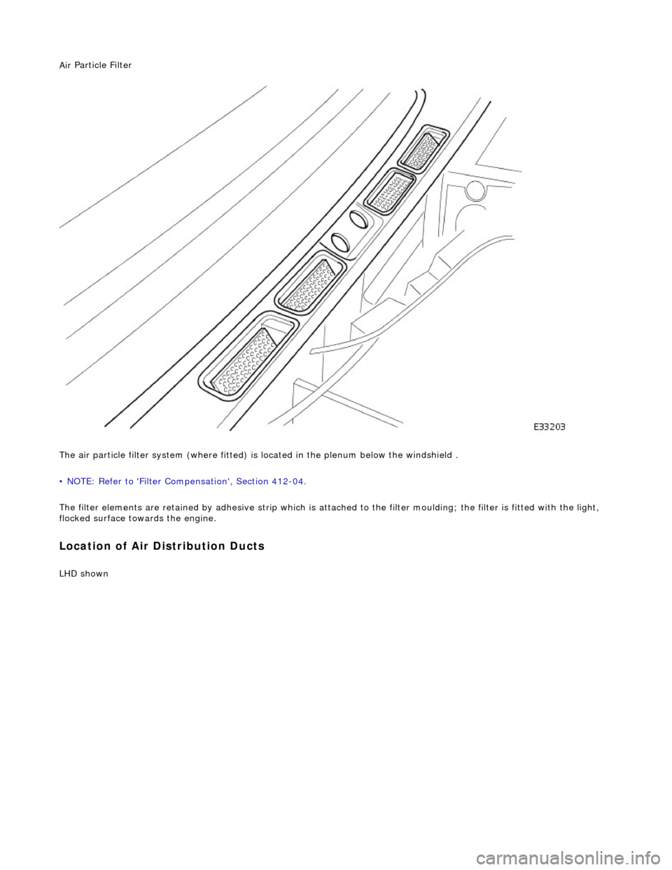
The air particle filter system (where fitted) is located in the plenum below the windshield .
• NOTE: Refer to 'Filter Compensation', Section 412-04.
The filter elements are retained by adhesive strip which is atta ched to the filter moulding; the filter is fitted with the light,
flocked surface towards the engine.
Loca
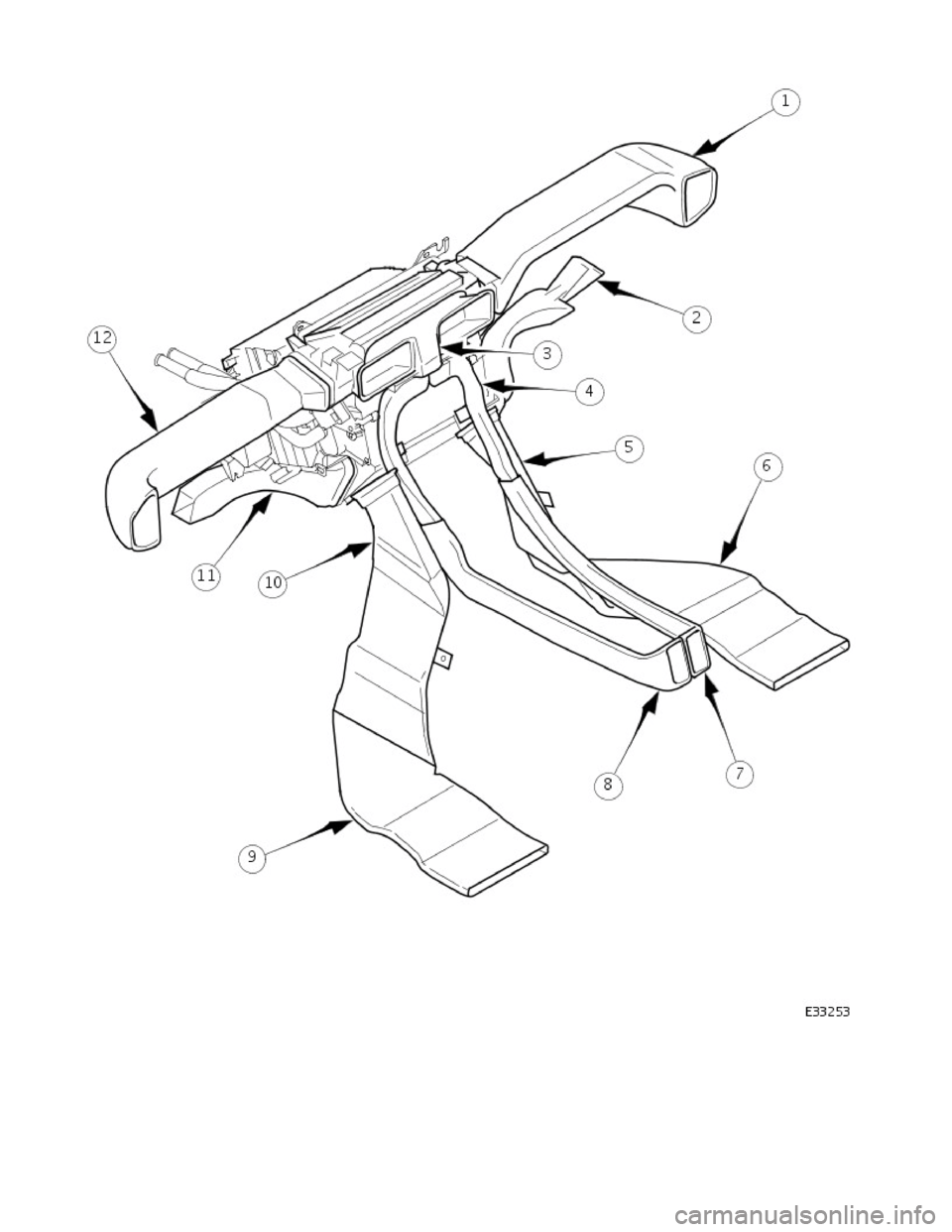
tion of Air Distribution Ducts
LHD s
hown
Page 1772 of 2490
Page 1773 of 2490
Ai
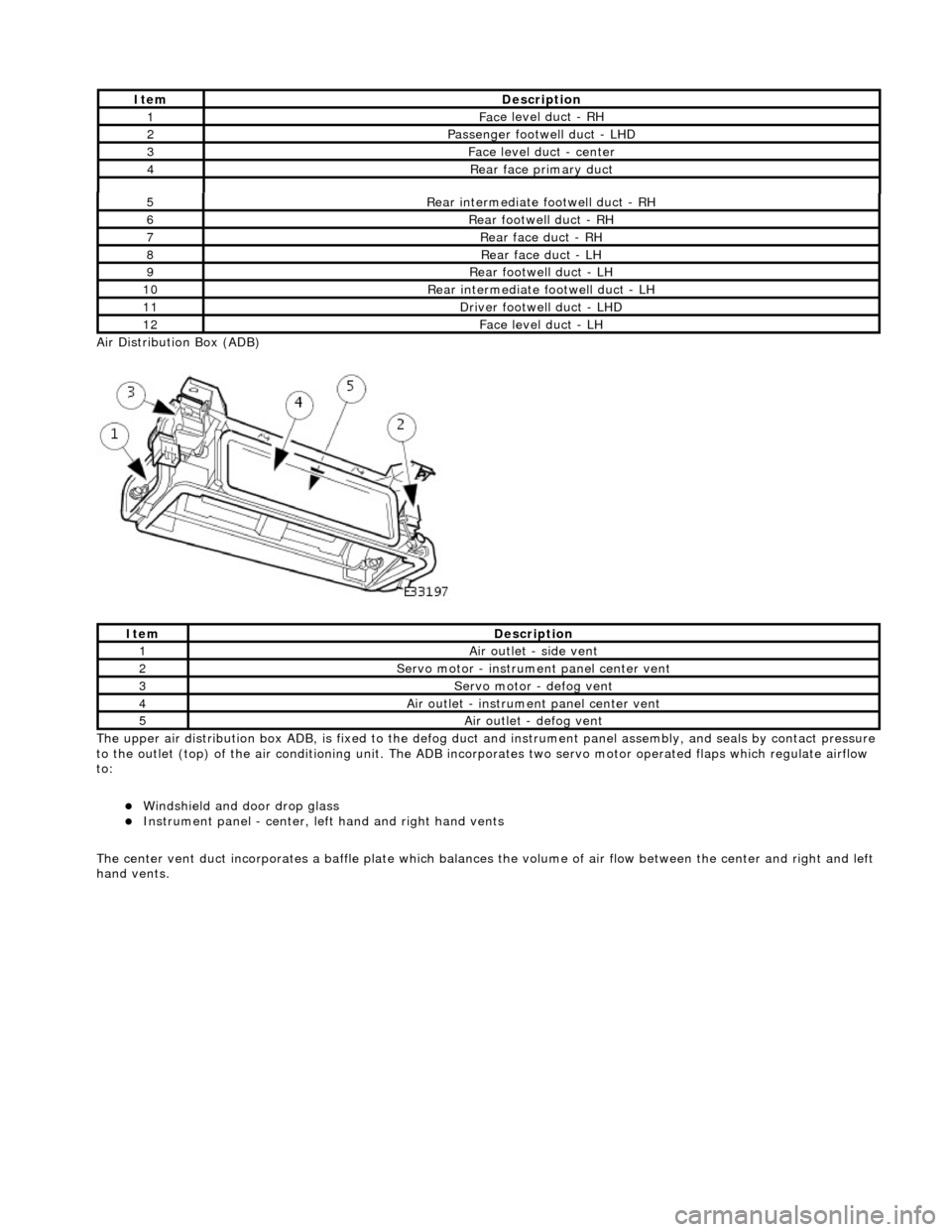
r Distribution Box (ADB)
The upper air distribution box ADB, is fixed to the defog duct and instrument panel assembly, and seals by contact pressure
to the outlet (top) of the air conditioning unit. The ADB inco rporates two servo motor operated flaps which regulate airflow
to:
Windshield and door drop
glass
Instrument panel
- center, left
hand and right hand vents
The center vent duct incorporat es a baffle plate which balances the volume of air flow between the center and right and left
hand vents.
5R
ear intermediate footwell duct - RH
6R
ear footwell duct - RH
7R
ear face duct - RH
8R
ear face duct - LH
9R
ear footwell duct - LH
10R
ear intermediate footwell duct - LH
11D
river footwell duct - LHD
12Fac
e level duct -
LH
It
em
De
scription
1Ai
r outlet - side vent
2Servo motor -
instrume
nt panel center vent
3Servo motor -
defog vent
4Ai
r outlet - instrume
nt panel center vent
5Ai
r outlet - defog vent
It
em
De
scription
1Fac
e level duct - RH
2Passenger footwel
l duct - LHD
3Fac
e level duct - center
4Rear
face primary duct
Page 1774 of 2490
I n
strument Pane
l Air Outlets
Ite
m
De
scr
iption
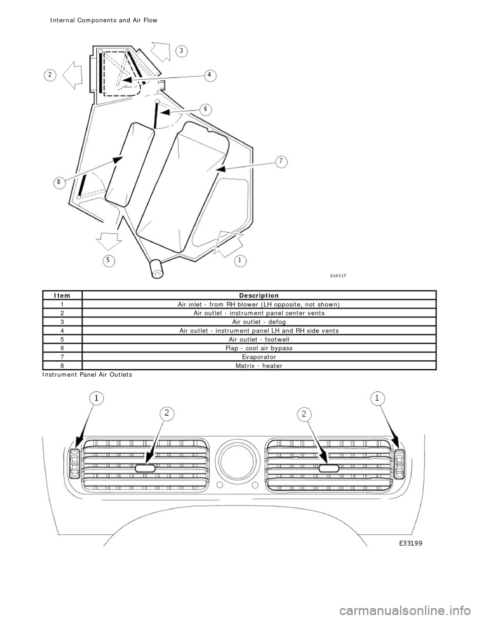
1Ai
r i
nlet - from RH blower (LH opposite, not shown)
2Ai
r outl
et - instrument
panel center vents
3Air ou
tlet - defog
4Ai
r outl
et - instru
ment panel LH and RH side vents
5Air outl
et - footwell
6Flap -
cool air
bypass
7Evaporator
8Matrix -
heater
Internal Components and Ai
r Fl
ow
Page 1775 of 2490
Ai
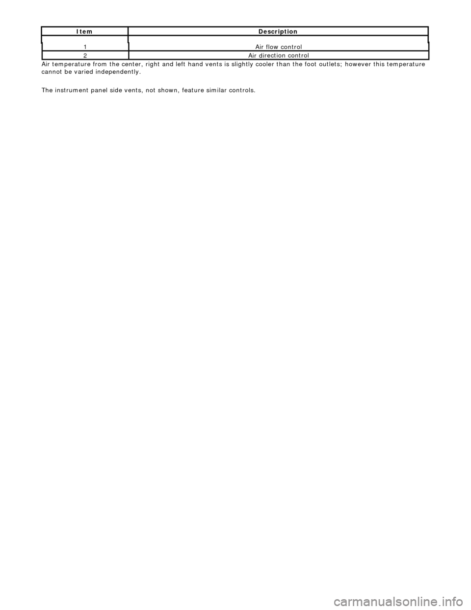
r temperature from the center, right and left
hand vents is slightly cooler than the foot outlets; however this temperature
cannot be varied independently.
The instrument panel side vents, not shown, feature similar controls.
1Ai
r flow control
2Air di
rection control
It
em
De
scription
Page 1776 of 2490
Air Distribution and Filtering - Air Distribution and Filtering
Diagnosis and Testing
Refer to section 412-00.
Page 1777 of 2490
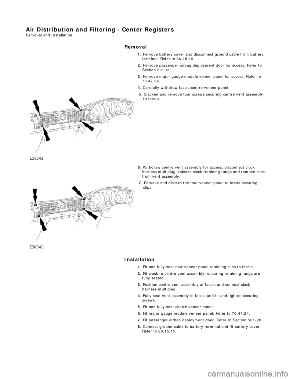
Air Distribution and Filtering - Center Registers
Removal and Installation
Removal
Installation
1.
Remove battery cover and disconnect ground cable from battery
terminal. Refer to 86.15.19.
2. Remove passenger airbag deployment door for access. Refer to
Section 501-20.
3. Remove major gauge module veneer panel for access. Refer to
76.47.24.
4. Carefully withdraw fascia centre veneer panel.
5. Slacken and remove four screws securing centre vent assembly
to fascia.
6. Withdraw centre vent assembly for access, disconnect clock
harness multiplug, release clock retaining tangs and remove clock
from vent assembly.
7. Remove and discard the four veneer panel to fascia securing
clips.
1. Fit and fully seat new veneer panel retaining clips to fascia.
2. Fit clock to centre vent assemb ly, ensuring retaining tangs are
fully seated.
3. Position centre vent assembly at fascia and connect clock
harness multiplug.
4. Fully seat vent assembly in fascia and fit and tighten securing
screws.
5. Fit and fully seat centre veneer panel.
6. Fit major gauge module veneer panel. Refer to 76.47.24.
7. Fit passenger airbag deployment door. Refer to Section 501-20.
8. Connect ground cable to battery terminal and fit battery cover.
Refer to 86.15.15.
Page 1778 of 2490
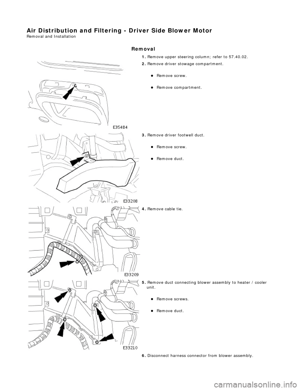
Air Distribution and Filtering - Driver Side Blower Motor
Removal and Installation
Removal
1. Remove upper steering co lumn; refer to 57.40.02.
2. Remove driver stowage compartment.
Remove screw.
Remove compartment.
3. Remove driver footwell duct.
Remove screw.
Remove duct.
4. Remove cable tie.
5. Remove duct connecting blower assembly to heater / cooler
unit.
Remove screws.
Remove duct.
6. Disconnect harness connector from blower assembly.
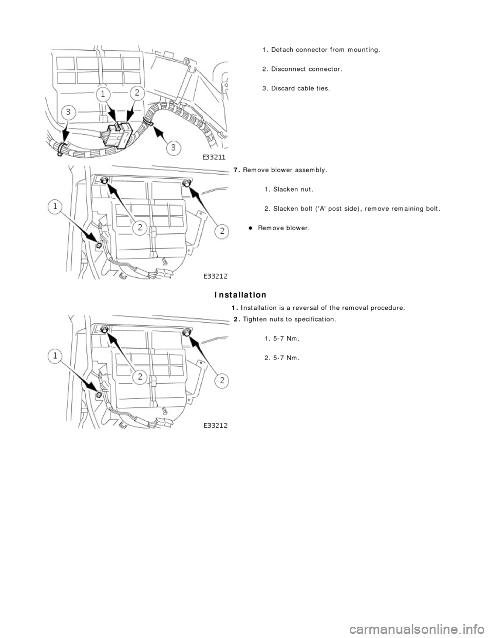
Page 1779 of 2490
Installation
1. Detach connector from mounting.
2. Disconnect connector.
3. Discard cable ties.
7. Remove blower assembly.
1. Slacken nut.
2. Slacken bolt ('A' post si de), remove remaining bolt.
Remove blower.
1. Installation is a reversal of the removal procedure.
2. Tighten nuts to specification.
1. 5-7 Nm.
2. 5-7 Nm.
Page 1780 of 2490
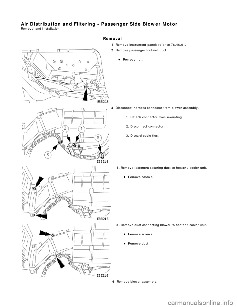
Air Distribution and Filtering - Passenger Side Blower Motor
Removal and Installation
Removal
1. Remove instrument panel; refer to 76.46.01.
2. Remove passenger footwell duct.
Remove nut.
3. Disconnect harness connector from blower assembly.
1. Detach connector from mounting.
2. Disconnect connector.
3. Discard cable ties.
4. Remove fasteners securing duct to heater / cooler unit.
Remove screws.
5. Remove duct connecting blower to heater / cooler unit.
Remove screws.
Remove duct.
6. Remove blower assembly.
Trending: roof rack, Seat, supercharger belt, rear brakes, subframe removal, driveshaft, Transmission Control Module
