JAGUAR X308 1998 2.G Workshop Manual
X308 1998 2.G
JAGUAR
JAGUAR
https://www.carmanualsonline.info/img/21/7640/w960_7640-0.png
JAGUAR X308 1998 2.G Workshop Manual
Trending: headlamp, fuel cap, vapour, component location, engine dtc, 19.60.04, Engine general
Page 1811 of 2490
Installation
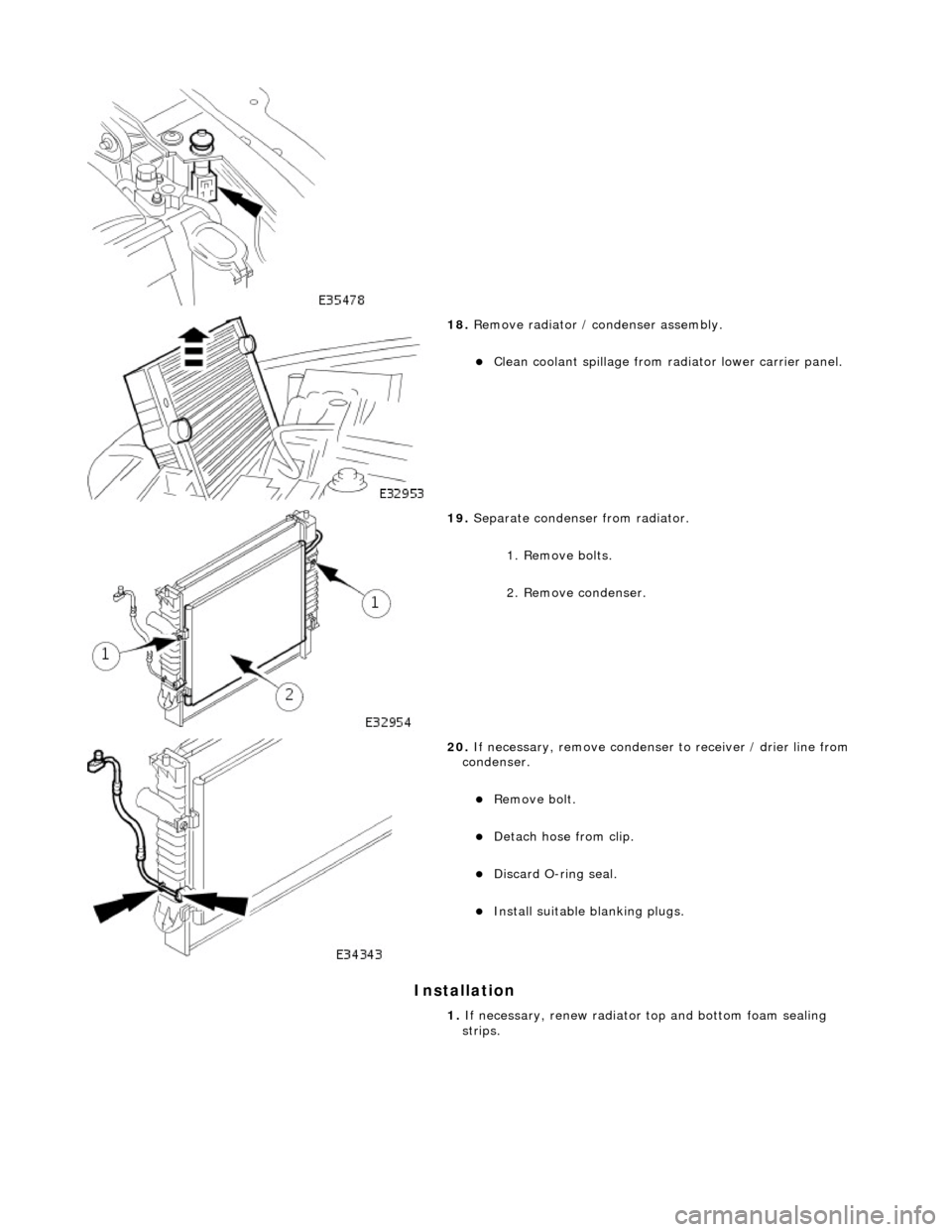
18. Remove radiator / condenser assembly.
Clean coolant spillage from radiator lower carrier panel.
19. Separate condenser from radiator.
1. Remove bolts.
2. Remove condenser.
20. If necessary, remove condenser to receiver / drier line from
condenser.
Remove bolt.
Detach hose from clip.
Discard O-ring seal.
Install suitable blanking plugs.
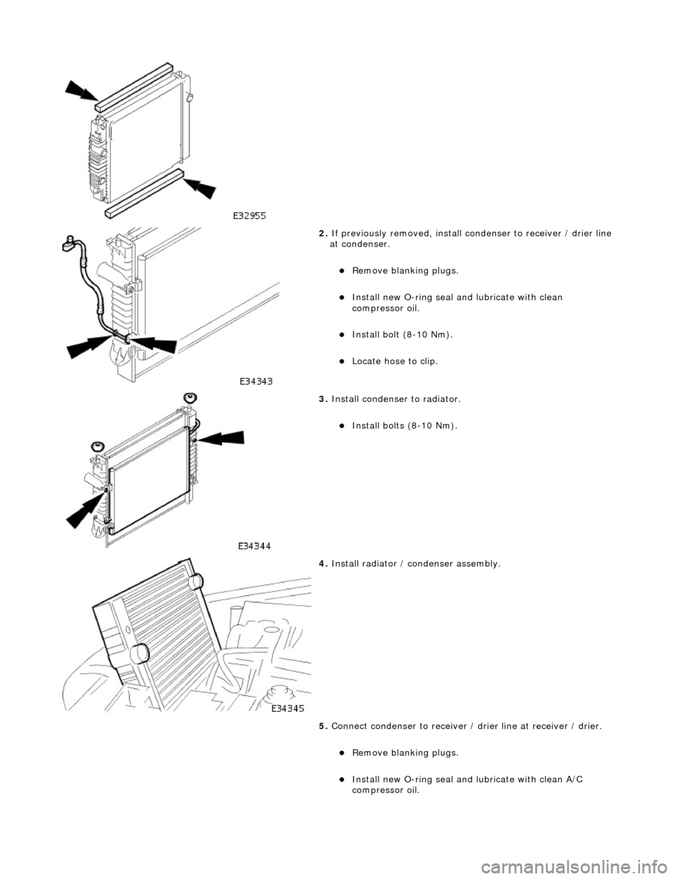
1. If necessary, renew radiator top and bottom foam sealing
strips.
Page 1812 of 2490
2. If previously removed, install condenser to receiver / drier line
at condenser.
Remove blanking plugs.
Install new O-ring seal and lubricate with clean
compressor oil.
Install bolt (8-10 Nm).
Locate hose to clip.
3. Install condenser to radiator.
Install bolts (8-10 Nm).
4. Install radiator / condenser assembly.
5. Connect condenser to receiver / dr ier line at receiver / drier.
Remove blanking plugs.
Install new O-ring seal and lubricate with clean A/C
compressor oil.
Page 1813 of 2490
Connect hose.
Install bolt (8-10 Nm).
6. Connect compressor to condenser discharge line at condenser.
Remove blanking plugs.
Install new O-ring seal an d lubricate with clean A/C
compressor oil.
Connect hose.
Install bolt (8-10 Nm).
7. Connect transmission o il cooler upper pipe.
Remove blanking plugs.
Install new O-ring seal and lu bricate with clean automatic
transmission fluid.
Connect union nut to radiator and tighten.
8. Connect transmission oil cooler lower pipe.
Remove blanking plugs.
Install new O-ring seal and lu bricate with clean automatic
transmission fluid.
9. Connect radiator blee d hose to radiator.
Page 1814 of 2490
10. Connect radiator top hose to radiator.
1. Connect top hose.
2. Reposition and tighten hose clip.
11. Install radiator retaining panel.
Install bolts and sequenti ally tighten from center
outwards.
12. Connect radiator bottom hose to radiator.
1. Connect bottom hose.
2. Reposition and tighten hose clip.
13. Install twin fan and motor as sembly; refer to 26.25.12.
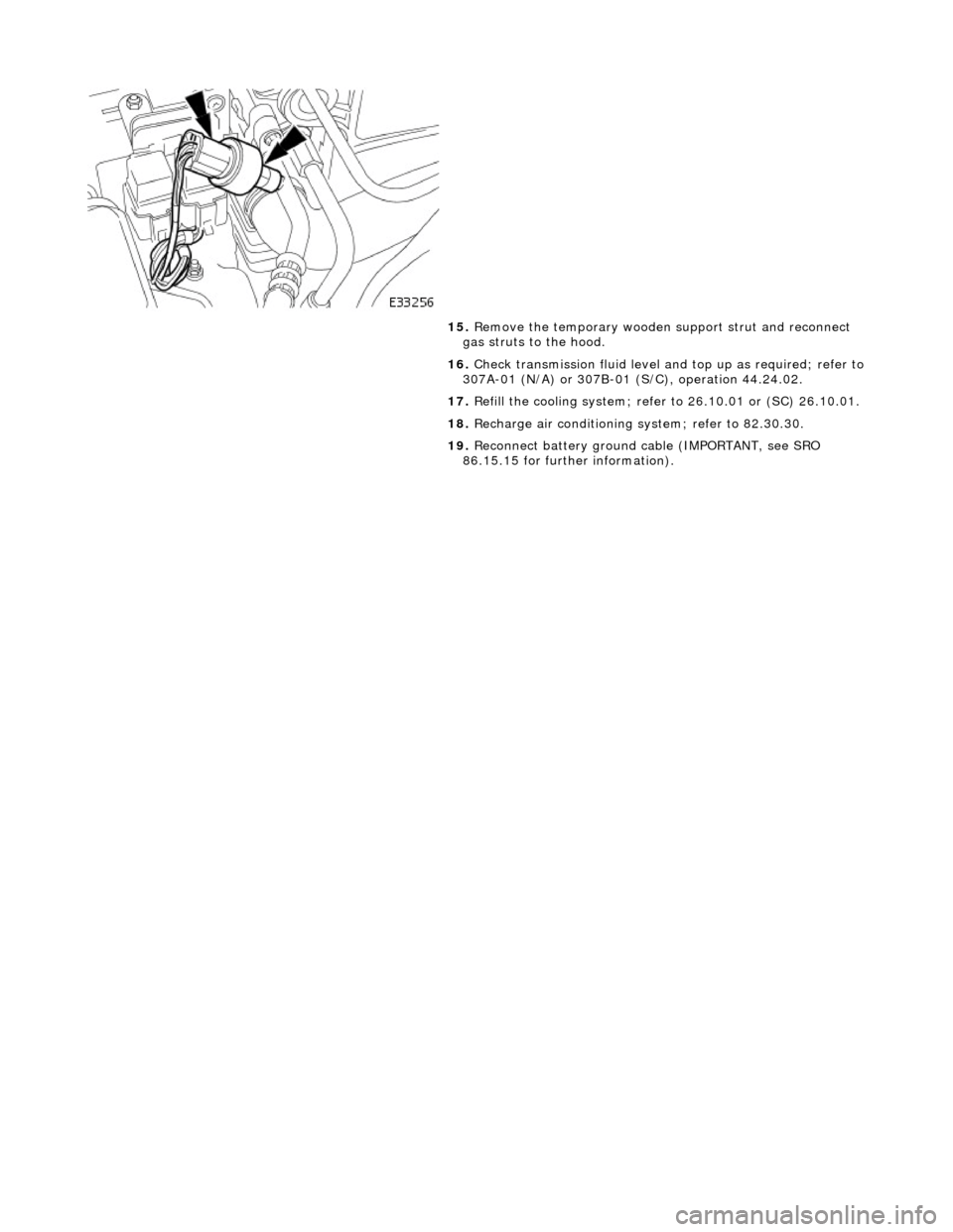
14. Connect pressure switch.
Page 1815 of 2490
15. Remove the temporary wooden support strut and reconnect
gas struts to the hood.
16. Check transmission fluid level an d top up as required; refer to
307A-01 (N/A) or 307B-01 (S/C), operation 44.24.02.
17. Refill the cooling system; refer to 26.10.01 or (SC) 26.10.01.
18. Recharge air conditioning system; refer to 82.30.30.
19. Reconnect battery ground cable (IMPORTANT, see SRO
86.15.15 for further information).
Page 1816 of 2490
Air Conditioning - Evaporator Core
Removal and Installation
Removal
1. Remove heater / cooler unit; refer to 82.25.21.
2. Remove air conditioning control module from heater / cooler
unit.
Slacken upper fixing.
Remove lower fixings.
3. Remove evaporator pipe firewall seal plate.
Remove screws.
Remove plate.
4. Disconnect heater matrix temperature sensor.
Detach heater matrix temperature sensor connector from
unit.
Disconnect connector.
5. Remove footwell servo motor from heater / cooler unit.
Disconnect connector.
Remove screws.
Remove motor complete with bracket.
6. Disconnect evaporator sensor connector.
Page 1817 of 2490
Installation
Detach heater / cooler unit connector.
Detach evaporator sensor connector.
Disconnect connector.
7. Remove heater / cooler unit upper case from lower case.
Remove screw.
Remove 15 clips.
Remove upper case from lower case.
8. Remove evaporator from case.
Remove sensor and clip.
Remove evaporator.
1. Installation is the reverse of removal.
Page 1818 of 2490
Air Conditioning - Pressure Cutoff Switch
Removal and Installation
Removal
Installation
1. Remove pressure switch.
Disconnect connector.
• NOTE: Discard O-ring seal.
Remove switch.
1. NOTE: Clean mating faces, instal l new O-ring seal and lubricate with clean compressor oil.
Installation is a reversal of the removal procedure.
Page 1819 of 2490
Air Conditioning - Receiver Drier
Removal and Installation
Removal
Installation
1. Disconnect battery ground cable (IMPORTANT, see SRO
86.15.19 for further information).
2. Remove air cleaner assemb ly; refer to 19.10.05.
3. Recover refrigerant from air co nditioning system; refer to
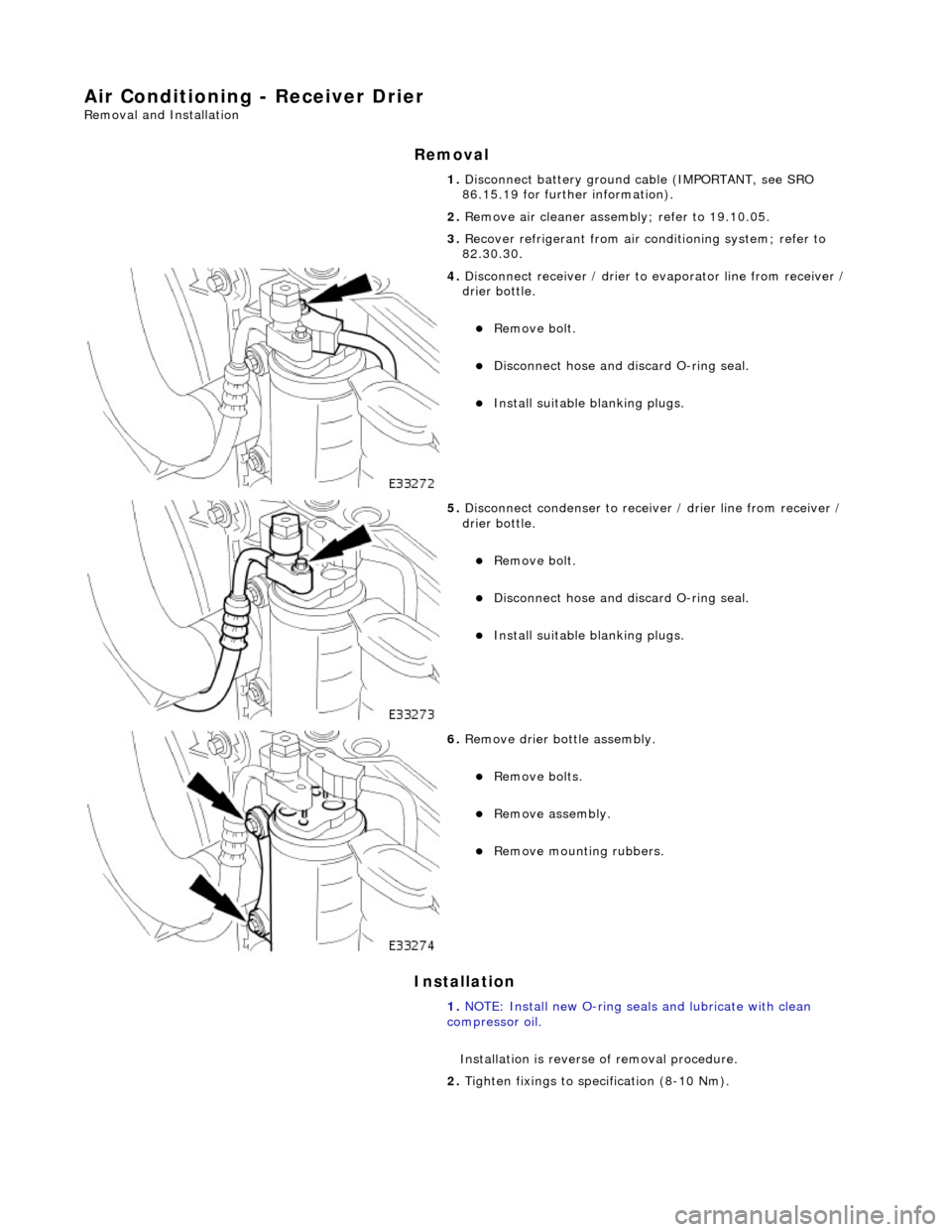
82.30.30.
4. Disconnect receiver / drier to evaporator line from receiver /
drier bottle.
Remove bolt.
Disconnect hose and discard O-ring seal.
Install suitable blanking plugs.
5. Disconnect condenser to receiver / drier line from receiver /
drier bottle.
Remove bolt.
Disconnect hose and discard O-ring seal.
Install suitable blanking plugs.
6. Remove drier bottle assembly.
Remove bolts.
Remove assembly.
Remove mounting rubbers.
1. NOTE: Install new O-ring seals and lubricate with clean
compressor oil.
Installation is reverse of removal procedure.
2. Tighten fixings to specification (8-10 Nm).
Page 1820 of 2490
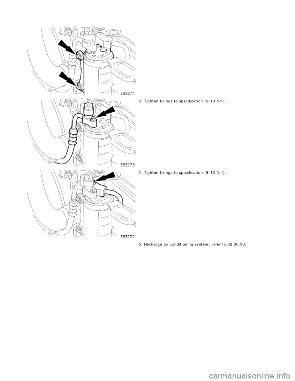
3. Tighten fixings to specification (8-10 Nm).
4. Tighten fixings to specification (8-10 Nm).
5. Recharge air conditioning system; refer to 82.30.30.
Trending: parking brake, trunk, fault code, reservoir, 310-01, 12.65.63, drawings
