lock JAGUAR X308 1998 2.G User Guide
[x] Cancel search | Manufacturer: JAGUAR, Model Year: 1998, Model line: X308, Model: JAGUAR X308 1998 2.GPages: 2490, PDF Size: 69.81 MB
Page 47 of 2490
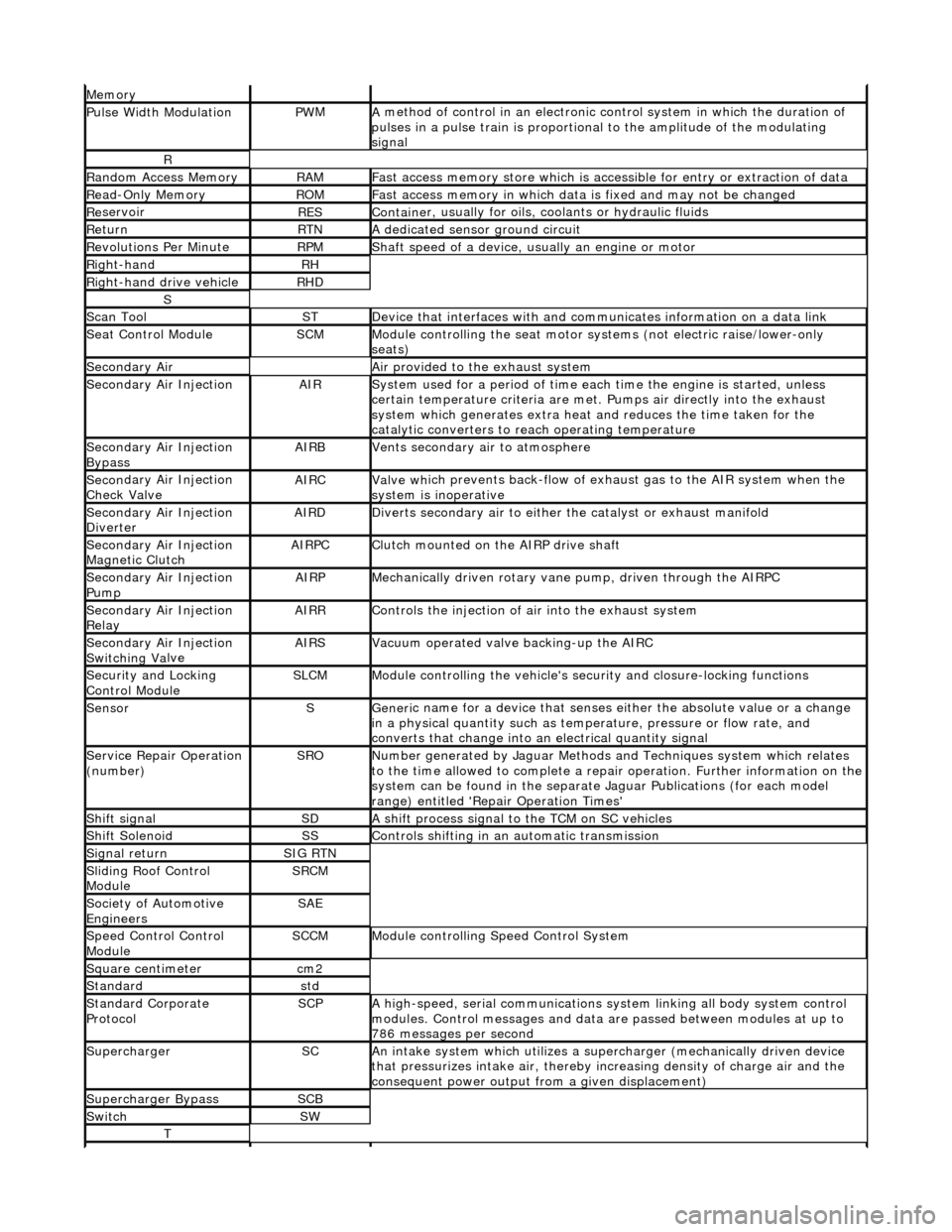
Mem
ory
Pulse Width ModulationPW
M
A
method of control in an electronic co
ntrol system in which the duration of
pulses in a pulse train is proportional to the amplitude of the modulating
signal
R
Ran
dom Access Memory
RAMF
ast access memory store which is accessible for entry or extraction of data
Re
ad-Only Memory
RO
M
F
ast access memory in which data
is fixed and may not be changed
Re
servoir
RESContaine
r, usually for oils,
coolants or hydraulic fluids
Re
turn
RTNA
dedicated sensor ground circuit
R
evolutions Per Minute
RP
M
Shaft speed o
f a device, us
ually an engine or motor
R
ight-hand
RH
Right-hand drive veh
icle
RHD
S
Scan T
ool
STDe
vice that interfaces with and comm
unicates information on a data link
Se
at Control Module
SCMModule
controlling the seat motor systems (not electric raise/lower-only
seats)
Secon
dary Air
Air pro
vided to the exhaust system
Secon
dary Air Injection
AIRSy
stem used for a period of time each
time the engine is started, unless
certain temperature criter ia are met. Pumps air directly into the exhaust
system which generates extra heat and reduces the time taken for the
catalytic converters to reach operating temperature
Secon
dary Air Injection
Bypass
AIRBVents secon
dary air to atmosphere
Secon
dary Air Injection
Check Valve
AIRCValve wh
ich prevents back-flow of exhaust gas to the AIR system when the
system is inoperative
Secon
dary Air Injection
Diverter
AIRDD
iverts secondary air to either
the catalyst or exhaust manifold
Secon
dary Air Injection
Magnetic Clutch
AIRP
C
Clu
tch mounted on the AIRP drive shaft
Secon
dary Air Injection
Pump
AIRPMe
chanically driven rotary vane
pump, driven through the AIRPC
Secon
dary Air Injection
Relay
AIRRCont
rols the injection of air into the exhaust system
Secon
dary Air Injection
Switchin
g Va
lve
AIRSV
acuum operated valve backing-up the AIRC
Secu
rity and Locking
Control Module
SLCMModul
e controlling the vehicle's security and closure-locking functions
SensorSGeneri
c name for a device
that senses either the absolute value or a change
in a physical quantity su ch as temperature, pressure or flow rate, and
converts that change into an electrical quantity signal
Servic
e Repair Operation
(number)
SRONu
mber generated by Jaguar Methods
and Techniques system which relates
to the time allowed to complete a repair operation. Further information on the
system can be found in the separate Jaguar Publications (for each model
range) entitled 'Repair Operation Times'
Shif
t signal
SDA
shift process signal to the TCM on SC vehicles
Shif
t Solenoid
SSControls shi
fting in an automatic transmission
Si
gnal return
SIG RTN
Slidin
g Roof Control
Module
SRCM
Society of Automotive
Engineers
SAE
Speed
Control Control
Module
SCCMModule con
trolling Speed Control System
Square c
entimeter
cm
2
Stan
dard
std
Stan
dard Corporate
Protocol
SCPA
high-speed, serial communications system linking all body system control
modules. Control messages and data ar e passed between modules at up to
786 messages per second
SuperchargerSCAn in
take system which utilizes a supercharger (mechanically driven device
that pressurizes intake air, thereby in creasing density of charge air and the
consequent power output from a given displacement)
Supercharger
Bypass
SCB
SwitchSW
T
Page 49 of 2490
Identification
Codes -
Identification Codes
Descr
iption and Operation
En
gine Number
The en
gine number (10 digits) is stamped on a raised pad on th
e front of the engine block near the thermostat housing. The
piston grade reference (8 digits) is also shown.
Automatic Transmission
Number
The
serial number of the transmission unit is displayed on
a metal or bar code label attached to the LH side of the
transmission casing.
Veh
icle Identification
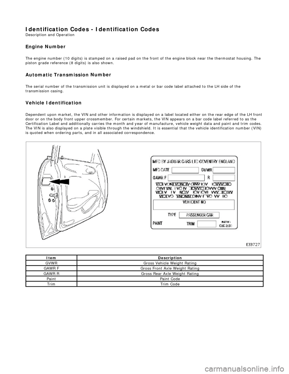
Dependent
upon market, the VIN and other info
rmation is displayed on a label located ei ther on the rear edge of the LH front
door or on the body front upper crossmember. For certain mark ets, the VIN appears on a bar code label referred to as the
Certification Label and additionally carries the month and year of manufacture, vehicle weight data and paint and trim codes.
The VIN is also displayed on a plate visible through the windshie ld. It is essential that the vehicle identification number (VIN)
is quoted when ordering parts, and in all associated correspondence.
ItemDe
scription
GVW
R
G
ross Vehicle Weight Rating
GAW
R F
Gros
s Front Axle Weight Rating
GAW
R R
Gros
s Rear Axle Weight Rating
Pai
nt
Pai
nt Code
TrimTrim
Code
Page 53 of 2490
Jacking and Lifting - Vehicle Recovery
Description an
d Operation
• NOTE: Prior to recovery, ensure that the vehicle keys are available and the security system disarmed.
Vehicle recovery methods are:
By fl
at-bed transporter.
By rear suspended tow.
By emergency to
wing for
very short distances.
Gears
hift Interlock
The
gear selector lever can only be moved
from the Park position by turning the igni tion key to position II and depressing
the brake pedal.
To remove the key from the ignition switch, the gear select or lever must be moved to the Park position. With the key
removed, the gear selector is locked in the Park position.
The selector lever can be manually unlocked from the Park position in the event of electrical failure or when moving the
vehicle without power. Refer to the general procedure in this section.
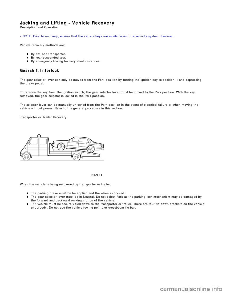
Transporter or Trailer Recovery
When the vehicle is being recove red by transporter or trailer:
The parking brake must be
be applied and the wheels chocked.
The
gear selector lever must be in Ne
utral. Do not select Park as the park ing lock mechanism may be damaged by
the forward and backward rocking motion of the vehicle.
The ve
hicle must be securely tied down to the transporter or
trailer. There are four tie-down brackets on the vehicle
underbody. Do not use the vehicle towing points or crossbeam tie bar.
Page 54 of 2490
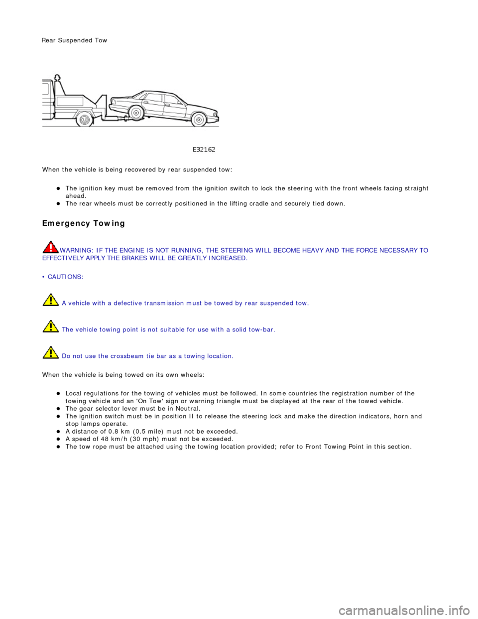
Wh en t
he vehicle is being reco
vered by rear suspended tow:
The ignition key must be remo ved from the ig
nition switch to lock the stee
ring with the front wheels facing straight
ahead.
The re ar
wheels must be
correctly positioned in the lifting cradle and securely tied down.
Em
ergency Towing
WARNING: IF THE
ENGINE IS NOT
RUNNING, THE STEERING WILL BECOME HEAVY AND THE FORCE NECESSARY TO
EFFECTIVELY APPLY THE BRAKES WILL BE GREATLY INCREASED.
• CAUTIONS:
A vehicle with a defective transmission must be towed by rear suspended tow.
The vehicle towing point is not suit able for use with a solid tow-bar.
Do not use the crossbeam tie bar as a towing location.
When the vehicle is being towed on its own wheels:
Loc a
l regulations for the towing of ve
hicles must be followed. In some co untries the registration number of the
towing vehicle and an 'On Tow' sign or warning triangle must be displayed at the rear of the towed vehicle.
The gear s
elector lever
must be in Neutral.
The
ignition switch must be in positi
on II to release the steering lock and make the direction indicators, horn and
stop lamps operate.
A di
stance of 0.8 km (0.5 mi
le) must not be exceeded.
A spe
ed of 48 km/h (30 mph) must not be exceeded.
The tow rope must be attached using th
e towi
ng location provided; refer to Front Towing Point in this section.
Rear Su
spended
Tow
Page 55 of 2490
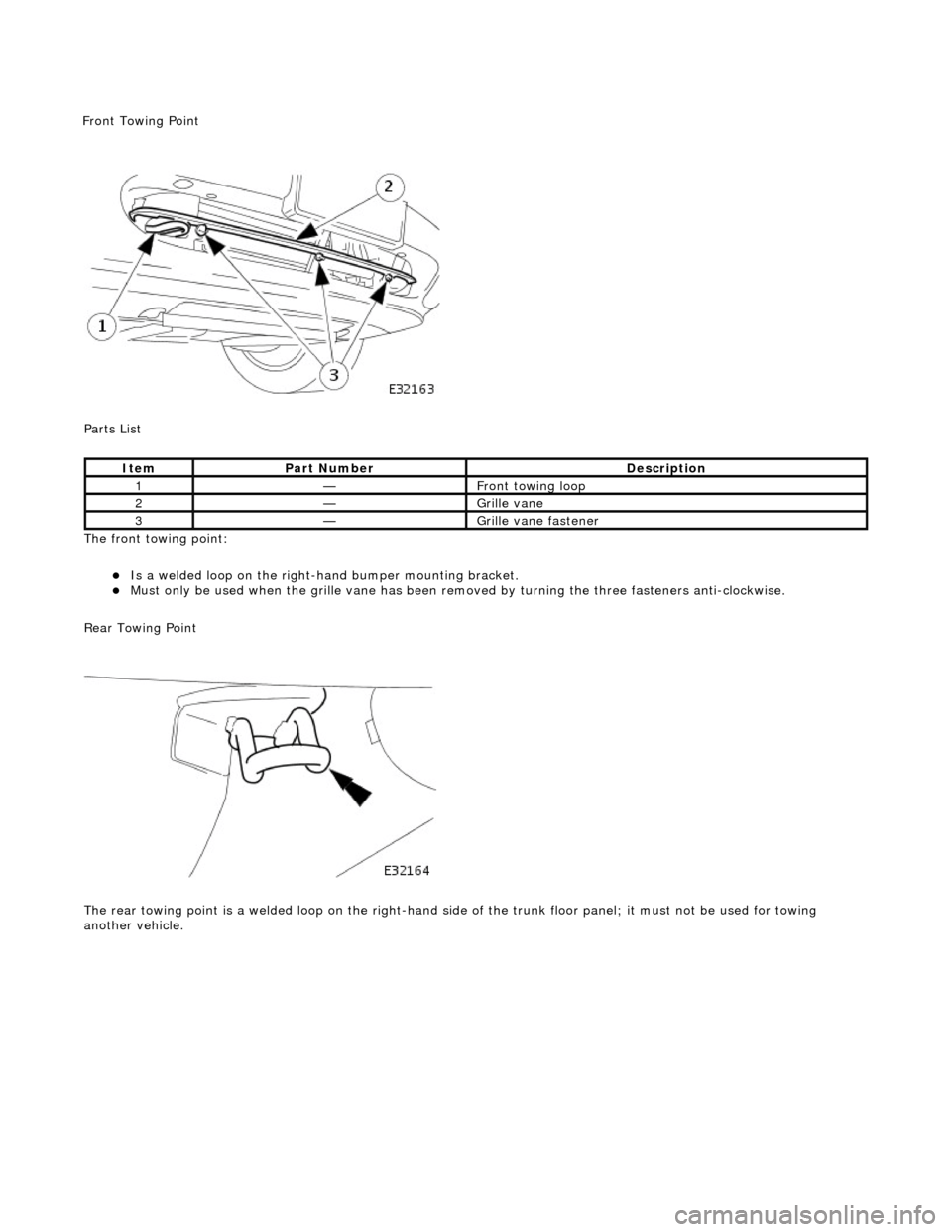
P
arts List
The front towing point:
Is a welded loop on the ri
ght-ha
nd bumper mounting bracket.
Mus
t only be used when the grille
vane has been removed by turning the three fasteners anti-clockwise.
Rear Towing Point
The rear towing point is a welded loop on the right-hand side of the trunk floor panel; it must not be used for towing
another vehicle.
It
em
Par
t Number
De
scription
1—Fr
ont towing loop
2—Gr
ille vane
3—Gr
ille vane fastener
F
ront Towing Point
Page 57 of 2490
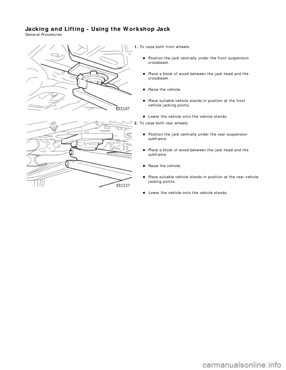
Jacking and Lifting - Using the Workshop Jack
Gen
eral Procedures
1.
To raise
both
front wheels:
P
osition the jack centrally
under the front suspension
crossbeam.
Pla
ce a block of wood between the jack head and the
crossbeam.
R
aise the vehicle.
P
lace suitable vehicle stands
in position at the front
vehicle jacking points.
Lo
wer the vehicle onto the vehicle stands.
2. To raise
both rear wheels:
P
osition the jack centrally
under the rear suspension
subframe.
Pla
ce a block of wood between the jack head and the
subframe.
R
aise the vehicle.
P
lace suitable vehicle stands in
position at the rear vehicle
jacking points.
Lo
wer the vehicle onto the vehicle stands.
Page 61 of 2490
Suspension System - General Information - Front Camber and Caster
Adjust
ment
Gen
eral Procedures
• NOTE: Before any work is commenced, th e vehicle must be checked to establish that it conforms to the Jaguar original
specification, e.g. wheels, ti res, tire pressures, etc.
• NOTE: The vehicle must be unladen and the fuel tank full when measuring suspension geometry.
1.
Road test the vehicle to establish the exact nature of the
complaint, e.g. pulling to one side, wander.
2. Measure the suspension geometry, fill in the 'Suspension
Geometry Record Form', and co ntact Jaguar Technical Support
for assistance.
3. Technical Support will give advice on the course of action to be
taken to rectify the problem.
4. Each lower wishbone pivots on and is secured to the front
crossbeam by two fulcrum bolts. A circular eccentric flange
formed under the hexagonal head of each fulcrum bolt, has
raised graduation marks to indicate radial position. A washer
with a 'D' shaped hole locates on a flat on the threaded section
of each bolt. This ensures that the washer rotates with the bolt,
maintaining an eccentric position corresponding with the
flanged head. The outer face of the washer is punch marked,
ensuring correct instal lation with the chamfered face inwards.
This permits the washer to rotate freely in the crossbeam cam
reaction plate during a djustm ent. Each fulcrum bolt and
washer are secured by a self locking nut.
On rotation of the bolt, lateral movement of the eccentric flange
and washer is restricted by the cam plate faces, forcing the bolt
shank to move laterally in the crossbeam slots. Lateral
movement of the bolt shank re sults in corresponding inward
and outward movement of th e wishbone arm, effecting
adjustment of wh eel alignment.
Rotation of the front fulcrum bolt principally adjusts wheel
caster angle, with a small amount of camber angle change.
Adjustment of the rear fulcrum bo lt mainly alters wheel camber
angle with a small amount of caster angle change.
On vehicles with VIN up to 833124, fulcrum bolt eccentric
flanges have raised graduation marks representing 15 degree
increments of bolt rotati on from 0 to 90 degrees.
On vehicles with VIN from 833125, the fulcrum bolt graduation
marks represent bolt shank ho rizontal movement in 1mm
increments from 0 to 3mm.
The upper wishbone and fulcrum shaft are not adjustable and
play no part in steering geometry adjustment.
Page 70 of 2490
Upper
Wishbones
Each
upper wi
shbone assembly is a on
e-piece steel forging incorporating:
A pres
s-fit ball joint.
Press-fi
t bushes for location of the upper fulcrum bolt.
Lower Wishbones
Each l
o
wer wishbone comprising
forged steel front and rear arms bolted together, incorporates:
A p
ress-fit ball joint in the outer extremity of the rear arm.
Press-f
i
t bushes for location of the lower fulcrum bolts
Locati
on for the shock absor
b
er lower mounting plates.
Vertica l Links
The vertical
links are of forged steel
wi
th integral steering arms. Each is suppo rted between the upper and lower wishbones
by two ball joints and carries:
Front hub
Brake ca
liper and disc shield assembly
ABS se
nsor
.
Front Hub
s
Each f
o
rged steel front hub accommodates sealed for life cartridge
type wheel bearings, and carries:
The brake rotor assembl
y.
A
h
ub nut with toothed, integral ABS rotor.
Su
s
pension spring pi
n locking device.
Front Road
Springs
The road spri
ng
s are of coil type with their
rating dependent upon vehicle specification
Ea
ch spring is installed between the suspension crossbeam location and the lower wishbone spring pan.
Ru
bber seats ar
e installed betw
een the spring and the crossb eam and the spring pan.
Front Shock A
bsorbers
Th
e
shock absorbers are telescopic hydrau
lically operated units. Optional adaptive damping units incorporate a solenoid-
operated control valve at their upper extremity.
Each shoc
k absorber is installed between the lowe
r wishbone rear arm and a recess in the body.
The l
o
wer end of the shock absorber is se
cured to plates on the wishbone by a bolt that also serves as a pivot.
The u
pper en
d of each shock absorber is secured to the body location by a single nut.
Front Sta
b
ilizer Bar
A
front stabil
izer bar installed on all vehicles
is rated according to suspension specification.
Opera
tion
As each road wheel r
i
ses, move
ment is transmitted through the vertical link assembly to the lower wishbone. The resulting
rise of the wishbone compresses the road spring and partially telescopes the shock absorber. During this action, the spring
absorbs associated shocks and the shock absorber minimizes sprin
g os c
illation.
Du
ring cornering, vehicle weight
is transferred to the outer road wheel with a resulting tendency for the inner wheel to lift.
The stabilizer bar assists in minimizing this tendency by transf erring a proportion of potential lift of the inner wheel to the
outer wheel. This result s in enhanced body stability with improved corner ing capabilities.
Page 71 of 2490

Front Suspension - Ba
ll Joint
Re
moval and Installation
Remov
al
• C
AUTIONS:
Replacement of nuts and bolts: Various thread-locking de vices are used on nuts and bolts throughout the vehicle.
These devices restrict the number of times a nut or bolt can be used. See section 100-00 for information.
The ball joint must be returned for wa rranty purposes, care must therefore be exercised to avoid damaging it during
removal. Any damage incurred during removal must be noted and recorded.
S
pecial Tool(s)
Ball
Joint Taper Separator
204-192 (JD 219)
Front Camber Tie-do
wn Link
204-114 (JD 133)
B
all Joint Remover
204-200 (JD 240)
B
all Joint Installer
204-199 (JD 239)
1. R
aise front of vehicle.
Refer to Section 100-02.
2. F
ully slacken adjuster nut of special tool 204-114 and position
tool in center of road spring .
Page 72 of 2490
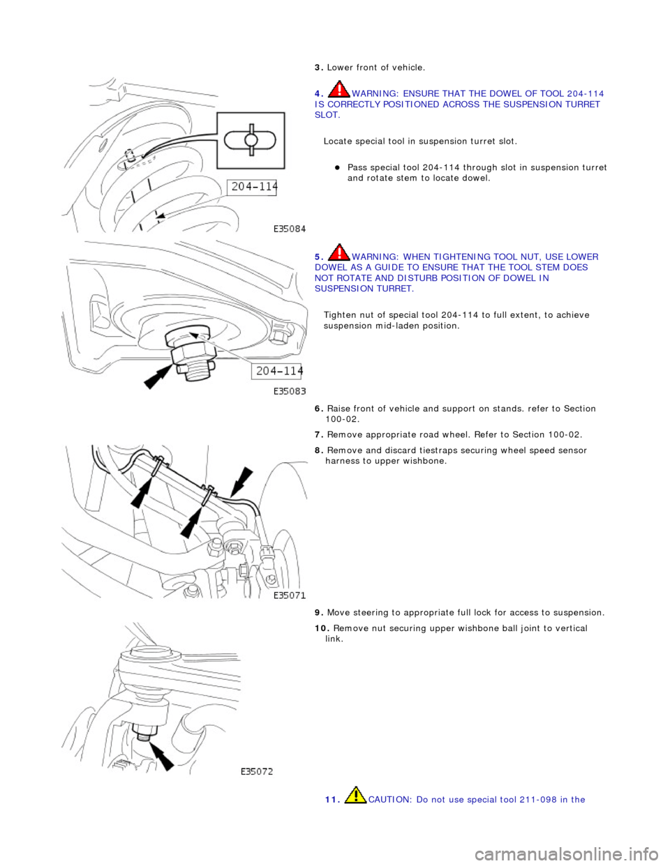
3. Lower front of vehicl
e.
4. W
A
RNING: ENSURE THAT THE DOWEL OF TOOL 204-114
IS CORRECTLY POSITIONED ACROSS THE SUSPENSION TURRET
SLOT.
Locate special tool in suspension turret slot.
Pas s
special tool 204-114 thro
ugh slot in suspension turret
and rotate stem to locate dowel.
5. WARNING: WHE N
TIGHTENING
TOOL NUT, USE LOWER
DOWEL AS A GUIDE TO ENSURE THAT THE TOOL STEM DOES
NOT ROTATE AND DISTURB POSITION OF DOWEL IN
SUSPENSION TURRET.
Tighten nut of special tool 204-114 to full extent, to achieve
suspension mid-laden position.
6. Ra
ise front of vehicle and support
on stands. refer to Section
100-02.
7. Remove appropriate road wheel. Refer to Section 100-02.
8. Remove an d discard tiestraps se
curing wheel speed sensor
harness to upper wishbone.
9. Move steering to appropriate full lock for access to suspension.
10 . R
emove nut securing upper wish
bone ball joint to vertical
link.
11. CAUTION: Do not use special tool 211-098 in the