box JAGUAR XFR 2010 1.G Workshop Manual
[x] Cancel search | Manufacturer: JAGUAR, Model Year: 2010, Model line: XFR, Model: JAGUAR XFR 2010 1.GPages: 3039, PDF Size: 58.49 MB
Page 1791 of 3039
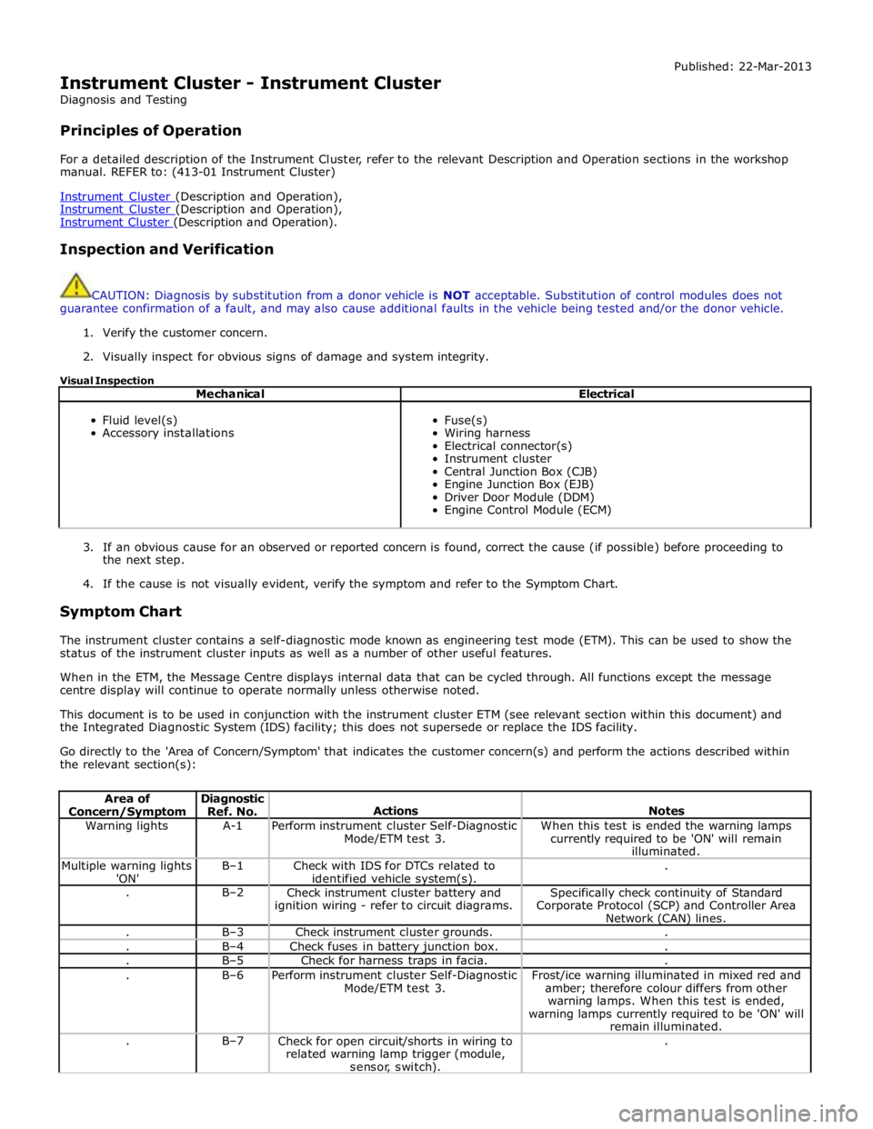
Instrument Cluster - Instrument Cluster
Diagnosis and Testing
Principles of Operation Published: 22-Mar-2013
For a detailed description of the Instrument Cluster, refer to the relevant Description and Operation sections in the workshop
manual. REFER to: (413-01 Instrument Cluster)
Instrument Cluster (Description and Operation), Instrument Cluster (Description and Operation), Instrument Cluster (Description and Operation).
Inspection and Verification
CAUTION: Diagnosis by substitution from a donor vehicle is NOT acceptable. Substitution of control modules does not
guarantee confirmation of a fault, and may also cause additional faults in the vehicle being tested and/or the donor vehicle.
1. Verify the customer concern.
2. Visually inspect for obvious signs of damage and system integrity.
Visual Inspection
Mechanical Electrical
Fluid level(s)
Accessory installations
Fuse(s)
Wiring harness
Electrical connector(s)
Instrument cluster
Central Junction Box (CJB)
Engine Junction Box (EJB)
Driver Door Module (DDM)
Engine Control Module (ECM)
3. If an obvious cause for an observed or reported concern is found, correct the cause (if possible) before proceeding to
the next step.
4. If the cause is not visually evident, verify the symptom and refer to the Symptom Chart.
Symptom Chart
The instrument cluster contains a self-diagnostic mode known as engineering test mode (ETM). This can be used to show the
status of the instrument cluster inputs as well as a number of other useful features.
When in the ETM, the Message Centre displays internal data that can be cycled through. All functions except the message
centre display will continue to operate normally unless otherwise noted.
This document is to be used in conjunction with the instrument cluster ETM (see relevant section within this document) and
the Integrated Diagnostic System (IDS) facility; this does not supersede or replace the IDS facility.
Go directly to the 'Area of Concern/Symptom' that indicates the customer concern(s) and perform the actions described within
the relevant section(s):
Area of Concern/Symptom Diagnostic
Ref. No.
Actions
Notes Warning lights A-1
Perform instrument cluster Self-Diagnostic
Mode/ETM test 3. When this test is ended the warning lamps
currently required to be 'ON' will remain
illuminated. Multiple warning lights
'ON' B–1
Check with IDS for DTCs related to
identified vehicle system(s). . . B–2
Check instrument cluster battery and
ignition wiring - refer to circuit diagrams. Specifically check continuity of Standard
Corporate Protocol (SCP) and Controller Area
Network (CAN) lines. . B–3 Check instrument cluster grounds. . . B–4 Check fuses in battery junction box. . . B–5 Check for harness traps in facia. . . B–6
Perform instrument cluster Self-Diagnostic
Mode/ETM test 3. Frost/ice warning illuminated in mixed red and
amber; therefore colour differs from other
warning lamps. When this test is ended,
warning lamps currently required to be 'ON' will
remain illuminated. . B–7
Check for open circuit/shorts in wiring to
related warning lamp trigger (module,
sensor, switch). .
Page 1797 of 3039
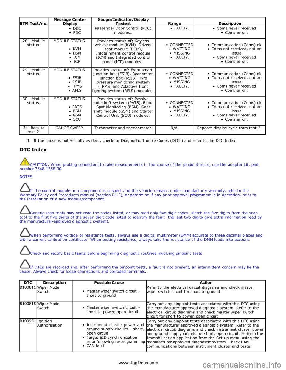
ETM Test/no. Message Center Display Gauge/Indicator/Display
Tested.
Range
Description DDC
PDC Passenger Door Control (PDC)
modules.. FAULTY.
Coms never received
Coms error . 28 - Module MODULE STATUS. Provides status of; Keyless
CONNECTED
Communication (Coms) ok status. vehicle module (KVM), Drivers KVM
seat module (DSM), WAITING Coms not received, not an DSM
Infotainment control module MISSING issue ICM
(ICM) and Integrated control FAULTY. Coms never received ICP
panel (ICP) modules.. Coms error . 29 - Module MODULE STATUS. Provides status of; Front smart
CONNECTED
Communication (Coms) ok status. junction box (FSJB), Rear smart FSJB
junction box (RSJB), Tyre WAITING Coms not received, not an RSJB
pressure monitoring system MISSING issue TPMS
(TPMS) and Adaptive front FAULTY. Coms never received AFLS
lighting system (AFLS) modules. Coms error . 30 - Module MODULE STATUS. Provides status of; Passive
CONNECTED
Communication (Coms) ok status. anti-theft system (PATS), Blind PATS
Spot Monitoring (BSM), Gear WAITING Coms not received, not an BSM
shift module (GSM) and Starter MISSING issue GSM
Control Unit (SCU) modules. FAULTY. Coms never received SCU Coms error . 31- Back to
test 2. GAUGE SWEEP. Tachometer and speedometer. N/A. Repeats display cycle from test 2.
1. If the cause is not visually evident, check for Diagnostic Trouble Codes (DTCs) and refer to the DTC Index.
DTC Index
CAUTION: When probing connectors to take measurements in the course of the pinpoint tests, use the adaptor kit, part
number 3548-1358-00
NOTES:
If the control module or a component is suspect and the vehicle remains under manufacturer warranty, refer to the
Warranty Policy and Procedures manual (section B1.2), or determine if any prior approval programme is in operation, prior to
the installation of a new module/component.
Generic scan tools may not read the codes listed, or may read only five digit codes. Match the five digits from the scan
tool to the first five digits of the seven digit code listed to identify the fault (the last two digits give extra information read by
the manufacturer-approved diagnostic system).
When performing voltage or resistance tests, always use a digital multimeter (DMM) accurate to three decimal places and
with a current calibration certificate. When testing resistance, always take the resistance of the DMM leads into account.
Check and rectify basic faults before beginning diagnostic routines involving pinpoint tests.
If DTCs are recorded and, after performing the pinpoint tests, a fault is not present, an intermittent concern may be the
cause. Always check for loose connections and corroded terminals.
DTC Description Possible Cause Action B100811
Wiper Mode
Switch
Master wiper switch circuit -
short to ground Refer to the electrical circuit diagrams and check master
wiper switch circuit for short to ground B100815
Wiper Mode
Switch
Master wiper switch circuit -
short to power, open circuit Carry out any pinpoint tests associated with this DTC using
the manufacturer approved diagnostic system. Refer to the
electrical circuit diagrams and check master wiper switch
circuit for short to power, open circuit B100951
Ignition
Authorisation
Instrument cluster power and
ground supply circuits - short,
open circuit
Target SID synchronization
error following re-programming
CAN fault Carry out any pinpoint tests associated with this DTC using
the manufacturer approved diagnostic system. Refer to the
electrical circuit diagrams and check instrument cluster power
and ground supply circuits for short, open circuit. Perform the
Immobilisation application from the Set-up menu using the
manufacturer approved diagnostic system. Check CAN
communications between instrument cluster and tester www.JagDocs.com
Page 1799 of 3039

DTC Description Possible Cause Action B100C67
Column Lock
Supply
Authorisation
Instrument cluster power and
ground supply circuits - short,
open circuit
LS CAN fault
CJB power and ground supply
circuits - short, open circuit
Vehicle speed present when
attempting to power ESCL
Engine speed present when
attempting to power ESCL
PowerMode status > 4 when
attempting to perform lock
action Carry out any pinpoint tests associated with this DTC using
the manufacturer approved diagnostic system. Refer to the
electrical circuit diagrams and check CJB power and ground
supply circuits for short, open circuit and instrument cluster
power and ground supply circuits for short, open circuit.
Check CAN communications between CJB and instrument
cluster. Check for invalid vehicle speed signal from
ABS/instrument cluster gateway. Check for invalid engine
speed signal from ECM/instrument cluster gateway. Check for
invalid signal from CJB B100C87
Column Lock
Supply
Authorisation
Instrument cluster power and
ground supply circuits - short,
open circuit
LS CAN fault
CJB power and ground supply
circuits - short, open circuit Carry out any pinpoint tests associated with this DTC using
the manufacturer approved diagnostic system. Refer to the
electrical circuit diagrams and check CJB power and ground
supply circuits for short, open circuit and instrument cluster
power and ground supply circuits for short, open circuit.
Check CAN communications between CJB and instrument
cluster B100D62
Column Lock
Authorisation
CAN fault
ESCL power and ground supply
circuits - short, open circuit
Instrument cluster power and
ground supply circuits - short,
open circuit
Incorrect ESCL or instrument
cluster installed
Target SID synchronization
error following re-programming
Noise/EMC related error Carry out any pinpoint tests associated with this DTC using
the manufacturer approved diagnostic system. Check CAN
communication between Electronic Steering Column Lock and
instrument cluster. Refer to the electrical circuit diagrams
and check Electronic Steering Column Lock power and ground
supply circuits for short, open circuit and Instrument cluster
power and ground supply circuits for short, open circuit.
Check correct Electronic Steering Column Lock and instrument
cluster installed. Perform the Immobilisation application from
the Set-up menu using the manufacturer approved diagnostic
system. Check CAN network for interference/EMC related
issues B100D64
Column Lock
Authorisation
Algorithm based failure-signal
plausibility failure
CAN fault
ESCL power and ground supply
circuits - short, open circuit
Instrument cluster power and
ground supply circuits - short,
open circuit If the customer has not reported a non start issue, clear the
DTC and check vehicle starts correctly. If a non start issue
has been reported run the manufacturers approved
diagnostic system Start Authorisation Application and follow
the actions required for this DTC. Carry out any pinpoint
tests associated with this DTC using the manufacturer
approved diagnostic system. Check CAN communication
between Electronic Steering Column Lock and instrument
cluster (check transmission out speed, vehicle speed, engine
speed, gear position and powermode signals to Electronic
Steering Column Lock). Refer to the electrical circuit
diagrams and check Electronic Steering Column Lock power
and ground supply circuits for short, open circuit and
Instrument cluster power and ground supply circuits for
short, open circuit. B100D87
Column Lock
Authorisation -
Missing message
Missing message
CAN fault
No response from electric
steering column lock control
module, instrument cluster,
central junction box Battery
voltage at electric
steering column lock control
module too low
Electric steering column lock
control module, instrument
cluster, central junction box
fault
Clear DTC, repeatedly lock and unlock car using the
key fob and retest. Check for related DTCs and refer
to the relevant DTC index
If the fault is cleared, notify the customer that the
steering column lock may fail to unlock if the vehicle
is parked with a high steering angle or with the road
wheel against a curb. If the column lock is failing to
disengage, the customer may be able to rectify this
by rotating the steering wheel while pressing the
engine start button
If fault persists, complete a CAN network integrity
test using the manufacturers approved diagnostic
system. Alternatively, refer to the electrical circuit
diagrams and check CAN circuits between the central
junction box, the instrument cluster and the
electronic steering column lock. Refer to the electrical
circuit diagrams and check the central junction box,
the instrument cluster and the electronic steering
column lock power and ground supply circuits for short
circuit to ground, short circuit to power, open circuit,
high resistance. Repair circuit(s) as required. Clear
DTC, perform an on demand self-test and retest
If fault persists, check that the vehicle battery supply
voltage is between 9-16 volts. Rectify as required
Page 1800 of 3039

DTC Description Possible Cause Action B100D96
Column Lock
Authorisation -
Component
internal failure
Battery voltage at electric
steering column lock control
module too low
Torque load on steering
column
CAN fault
Electric steering column lock
control module - Internal
failure
Clear DTC, repeatedly lock and unlock car using the
key fob and retest
If fault persists, check that the vehicle battery supply
voltage is between 9-16 volts. Rectify as required
Ensure the column lock bolt movement is not
obstructed or restricted (the parked position of the
road wheels may be exerting a turning force through
the steering column, preventing the lock from
releasing. The steering wheel may need to be held
against the force to allow the column lock to
release). Clear DTC, repeatedly lock and unlock car
using the key fob and retest
If fault persists, complete a CAN network integrity
test using the manufacturers approved diagnostic
system. Alternatively, refer to the electrical circuit
diagrams and check CAN circuits between the central
junction box, the instrument cluster and the
electronic steering column lock. Refer to the electrical
circuit diagrams and check the central junction box,
the instrument cluster and the electronic steering
column lock power and ground supply circuits for short
circuit to ground, short circuit to power, open circuit,
high resistance. Repair circuit(s) as required. Clear
DTC, perform an on demand self-test and retest
If fault persists, check and install a new electric
steering column lock control module as required B102487 Start Control Unit
Smart card docking station
failure - slave node not
responding Carry out any pinpoint tests associated with this DTC using
the manufacturer approved diagnostic system. Refer to the
electrical circuit diagrams and check the smart card docking
station LIN circuit for short, open circuit. Suspect the smart
card docking station, check and install a new docking station
as required, refer to the new module/component installation
note at the top of the DTC Index B104611
Front Fog Lamp
Control Switch
Fog lamp switch circuit - short
to ground Refer to the electrical circuit diagrams and check fog lamp
switch circuit for short to ground B104615
Front Fog Lamp
Control Switch
Fog lamp switch circuit - short
to power, open circuit Refer to the electrical circuit diagrams and check fog lamp
switch circuit for short to power, open circuit B104811
Brake Fluid Level
Switch
Brake fluid level switch circuit
- short to ground Refer to the electrical circuit diagrams and check brake fluid
level switch circuit for short to ground B10A011
Wiper/ Washer
Switch
Wash/wipe circuit - short to
ground Refer to the electrical circuit diagrams and check wash/wipe
circuit for short to ground B10A015
Wiper/ Washer
Switch
Wash/wipe circuit - short to
power, open circuit Carry out any pinpoint tests associated with this DTC using
the manufacturer approved diagnostic system. Refer to the
electrical circuit diagrams and check wash/wipe circuit for
short to power, open circuit B10A611 Main Light Switch
Master lighting switch circuit -
short to ground Refer to the electrical circuit diagrams and check master
lighting switch circuit for short to ground B10A615 Main Light Switch
Master lighting switch circuit -
short to power, open circuit Carry out any pinpoint tests associated with this DTC using
the manufacturer approved diagnostic system. Refer to the
electrical circuit diagrams and check master lighting switch
circuit for short to power, open circuit B112B87
Steering Wheel
Module
Steering wheel module failure
- slave node not responding Carry out any pinpoint tests associated with this DTC using
the manufacturer approved diagnostic system. Refer to the
electrical circuit diagrams and check the clockspring LIN
circuit for short, open circuit. Suspect the clockspring, check
and install a new clockspring as required, refer to the new
module/component installation note at the top of the DTC
Index B115C7A
Transfer Fuel
Pump
Fuel pump system fault Check for fuel system jet pump or jet pump fuel level sensor
fault B1A8515
Ambient Light
Sensor
Autolamp sensor circuit - short
to power, open circuit Carry out any pinpoint tests associated with this DTC using
the manufacturer approved diagnostic system. Refer to the
electrical circuit diagrams and check autolamp sensor circuit
for short to power, open circuit
Page 1825 of 3039
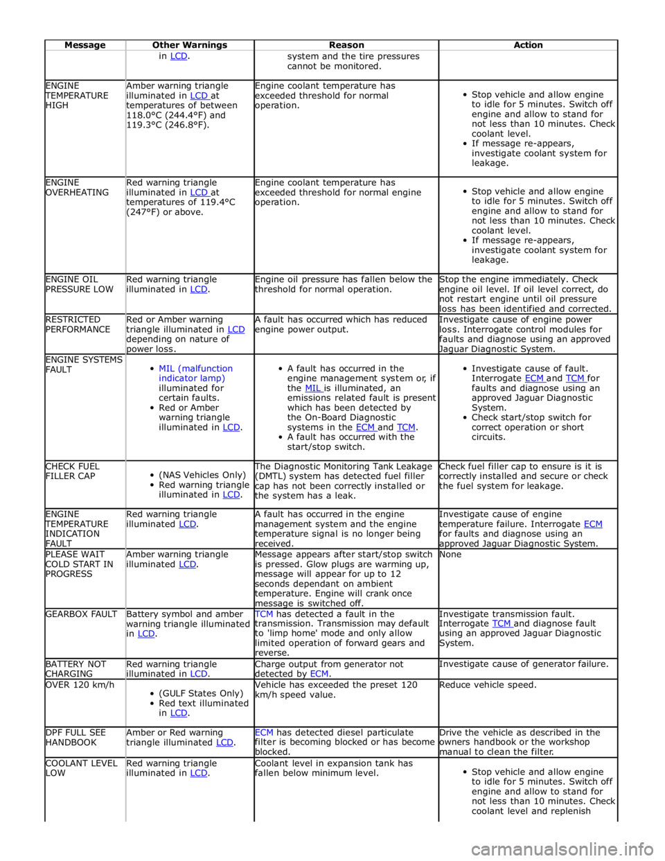
Message Other Warnings Reason Action in LCD. system and the tire pressures
cannot be monitored. ENGINE TEMPERATURE
HIGH Amber warning triangle
illuminated in LCD at temperatures of between
118.0°C (244.4°F) and
119.3°C (246.8°F). Engine coolant temperature has
exceeded threshold for normal
operation.
Stop vehicle and allow engine
to idle for 5 minutes. Switch off
engine and allow to stand for
not less than 10 minutes. Check
coolant level.
If message re-appears,
investigate coolant system for
leakage. ENGINE
OVERHEATING Red warning triangle
illuminated in LCD at temperatures of 119.4°C
(247°F) or above. Engine coolant temperature has
exceeded threshold for normal engine
operation.
Stop vehicle and allow engine
to idle for 5 minutes. Switch off
engine and allow to stand for
not less than 10 minutes. Check
coolant level.
If message re-appears,
investigate coolant system for
leakage. ENGINE OIL
PRESSURE LOW Red warning triangle
illuminated in LCD. Engine oil pressure has fallen below the
threshold for normal operation. Stop the engine immediately. Check
engine oil level. If oil level correct, do
not restart engine until oil pressure
loss has been identified and corrected. RESTRICTED
PERFORMANCE Red or Amber warning
triangle illuminated in LCD depending on nature of power loss. A fault has occurred which has reduced
engine power output. Investigate cause of engine power
loss. Interrogate control modules for
faults and diagnose using an approved Jaguar Diagnostic System. ENGINE SYSTEMS
FAULT
MIL (malfunction
indicator lamp)
illuminated for
certain faults.
Red or Amber
warning triangle
illuminated in LCD.
A fault has occurred in the
engine management system or, if
the MIL is illuminated, an emissions related fault is present
which has been detected by
the On-Board Diagnostic
systems in the ECM and TCM. A fault has occurred with the
start/stop switch.
Investigate cause of fault.
Interrogate ECM and TCM for faults and diagnose using an
approved Jaguar Diagnostic
System.
Check start/stop switch for
correct operation or short
circuits. CHECK FUEL
FILLER CAP
(NAS Vehicles Only)
Red warning triangle
illuminated in LCD. The Diagnostic Monitoring Tank Leakage
(DMTL) system has detected fuel filler
cap has not been correctly installed or
the system has a leak. Check fuel filler cap to ensure is it is
correctly installed and secure or check
the fuel system for leakage. ENGINE TEMPERATURE
INDICATION
FAULT Red warning triangle
illuminated LCD. A fault has occurred in the engine
management system and the engine
temperature signal is no longer being
received. Investigate cause of engine
temperature failure. Interrogate ECM for faults and diagnose using an approved Jaguar Diagnostic System. PLEASE WAIT
COLD START IN
PROGRESS Amber warning triangle
illuminated LCD. Message appears after start/stop switch
is pressed. Glow plugs are warming up,
message will appear for up to 12
seconds dependant on ambient
temperature. Engine will crank once message is switched off. None GEARBOX FAULT
Battery symbol and amber
warning triangle illuminated
in LCD. TCM has detected a fault in the Investigate transmission fault. transmission. Transmission may default
to 'limp home' mode and only allow
limited operation of forward gears and
reverse. Interrogate TCM and diagnose fault using an approved Jaguar Diagnostic
System. BATTERY NOT
CHARGING Red warning triangle
illuminated in LCD. Charge output from generator not
detected by ECM. Investigate cause of generator failure. OVER 120 km/h
(GULF States Only)
Red text illuminated
in LCD. Vehicle has exceeded the preset 120
km/h speed value. Reduce vehicle speed. DPF FULL SEE
HANDBOOK Amber or Red warning
triangle illuminated LCD. ECM has detected diesel particulate Drive the vehicle as described in the filter is becoming blocked or has become
blocked. owners handbook or the workshop
manual to clean the filter. COOLANT LEVEL
LOW Red warning triangle
illuminated in LCD. Coolant level in expansion tank has
fallen below minimum level.
Stop vehicle and allow engine
to idle for 5 minutes. Switch off
engine and allow to stand for
not less than 10 minutes. Check
coolant level and replenish
Page 1827 of 3039
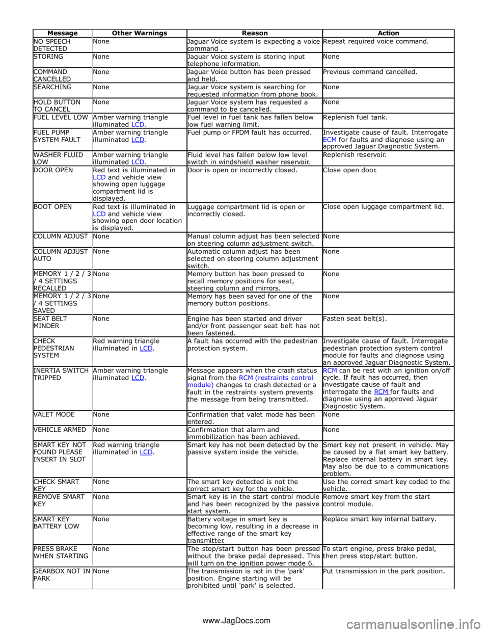
NO SPEECH
DETECTED None
Jaguar Voice system is expecting a voice
command . Repeat required voice command. STORING None
Jaguar Voice system is storing input telephone information. None COMMAND
CANCELLED None
Jaguar Voice button has been pressed
and held. Previous command cancelled. SEARCHING None
Jaguar Voice system is searching for requested information from phone book. None HOLD BUTTON TO CANCEL None
Jaguar Voice system has requested a
command to be cancelled. None FUEL LEVEL LOW
Amber warning triangle
illuminated LCD. Fuel level in fuel tank has fallen below
low fuel warning limit. Replenish fuel tank. FUEL PUMP
SYSTEM FAULT Amber warning triangle
illuminated LCD. Fuel pump or FPDM fault has occurred.
Investigate cause of fault. Interrogate
ECM for faults and diagnose using an approved Jaguar Diagnostic System. WASHER FLUID
LOW Amber warning triangle
illuminated LCD. Fluid level has fallen below low level
switch in windshield washer reservoir. Replenish reservoir. DOOR OPEN
Red text is illuminated in
LCD and vehicle view Door is open or incorrectly closed. Close open door. showing open luggage
compartment lid is
displayed. BOOT OPEN
Red text is illuminated in
LCD and vehicle view Luggage compartment lid is open or incorrectly closed. Close open luggage compartment lid. showing open door location
is displayed. COLUMN ADJUST None
Manual column adjust has been selected
on steering column adjustment switch. None COLUMN ADJUST
AUTO None
Automatic column adjust has been
selected on steering column adjustment
switch. None MEMORY 1 / 2 / 3 / 4 SETTINGS
RECALLED None
Memory button has been pressed to
recall memory positions for seat, steering column and mirrors. None MEMORY 1 / 2 / 3 / 4 SETTINGS
SAVED None
Memory has been saved for one of the
memory button positions. None SEAT BELT
MINDER None
Engine has been started and driver
and/or front passenger seat belt has not
been fastened. Fasten seat belt(s). CHECK
PEDESTRIAN
SYSTEM Red warning triangle
illuminated in LCD. A fault has occurred with the pedestrian
protection system. Investigate cause of fault. Interrogate
pedestrian protection system control
module for faults and diagnose using
an approved Jaguar Diagnostic System. INERTIA SWITCH TRIPPED Amber warning triangle
illuminated LCD. Message appears when the crash status
signal from the RCM (restraints control
module) changes to crash detected or a
fault in the restraints system prevents
the message from being transmitted. RCM can be rest with an ignition on/off cycle. If fault has occurred, then
investigate cause of fault and
interrogate the RCM for faults and diagnose using an approved Jaguar
Diagnostic System. VALET MODE None
Confirmation that valet mode has been
entered. None VEHICLE ARMED None
Confirmation that alarm and
immobilization has been achieved. None SMART KEY NOT
FOUND PLEASE
INSERT IN SLOT Red warning triangle
illuminated in LCD. Smart key has not been detected by the
passive system inside the vehicle. Smart key not present in vehicle. May
be caused by a flat smart key battery.
Replace internal battery in smart key.
May also be due to a communications problem. CHECK SMART
KEY None The smart key detected is not the
correct smart key for the vehicle. Use the correct smart key coded to the
vehicle. REMOVE SMART
KEY None
Smart key is in the start control module
and has been recognized by the passive
start system. Remove smart key from the start
control module. SMART KEY
BATTERY LOW None
Battery voltage in smart key is
becoming low, resulting in a decrease in
effective range of the smart key
transmitter. Replace smart key internal battery. PRESS BRAKE
WHEN STARTING None The stop/start button has been pressed
without the brake pedal depressed. This
will turn on the ignition power mode 6. To start engine, press brake pedal,
then press stop/start button. GEARBOX NOT IN
PARK None The transmission is not in the 'park'
position. Engine starting will be prohibited until 'park' is selected. Put transmission in the park position. www.JagDocs.com
Page 1828 of 3039
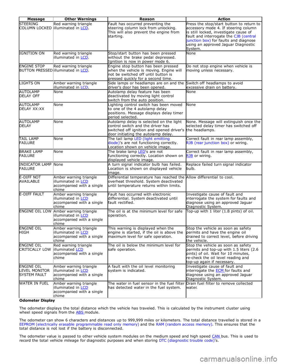
STEERING
COLUMN LOCKED Red warning triangle
illuminated in LCD. Fault has occurred preventing the
steering column lock from unlocking. This will also prevent the engine from
starting. Press the stop/start button to return to
accessory mode 4. If steering column
is still locked, investigate cause of
fault and interrogate the CJB (central junction box) for faults and diagnose
using an approved Jaguar Diagnostic System. IGNITION ON
Red warning triangle
illuminated in LCD. Stop/start button has been pressed
without the brake pedal depressed. Ignition is now in power mode 6. None ENGINE STOP
BUTTON PRESSED Red warning triangle
illuminated in LCD. Engine stop button has been pressed
when the vehicle is moving. Engine will
not be switched off until button is pressed quickly for a second time. Do not stop engine when vehicle is
moving unless necessary. LIGHTS ON
Amber warning triangle
illuminated in LCD. Side lamps or headlamps are on and the
driver's door has been opened. Switch off headlamps to avoid
excessive drain on battery. AUTOLAMP
DELAY OFF None
Autolamp delay feature has been
deactivated by moving light control
switch from the auto position. None AUTOLAMP
DELAY XX:XX None
Lighting control switch has been moved
to one of the 4 autolamp delay
positions. Message displays delay timer period selected. None AUTOLAMP
DELAY None
Autolamp delay is selected on the light
control switch and the driver has
switched off ignition and opened driver's
door initiating the autolamp delay. None. Message will extinguish once the
selected delay timer has switched off
the headlamps. TAIL LAMP
FAILURE None The tail lamp LED (light emitting
diode)'s are not functioning correctly.
Location shown on vehicle image. Correct fault in rear lamp assembly,
RJB (rear junction box) or wiring. BRAKE LAMP
FAILURE None The brake lamp LED's are not functioning correctly. Location shown on displayed vehicle image. Correct fault in rear lamp assembly,
RJB or wiring. INDICATOR LAMP
FAILURE None
A turn signal indicator bulb has failed.
Location is shown on displayed vehicle image. Replace failed turn signal indicator
bulb. E-DIFF NOT
AVAILABLE Amber warning triangle
illuminated in LCD accompanied with a single
chime Differential temperature has reached the
overheat threshold. System deactivated
until temperature returns within limits. Allow differential to cool. E-DIFF FAULT
Amber warning triangle
illuminated in LCD accompanied with a single
chime Fault has occurred with electronic
differential. System deactivated until
fault rectified. Investigate cause of fault and
interrogate the system for faults and
diagnose using an approved Jaguar Diagnostic System. ENGINE OIL LOW
Amber warning triangle
illuminated in LCD accompanied with a single
chime The oil is at the minimum level for safe
operation. Top-up with 1 liter (1.8 pints) of oil. ENGINE OIL
HIGH Amber warning triangle
illuminated in LCD accompanied with a single
chime This warning is displayed when the
engine is started, if the oil is above the
maximum level for safe operation. Stop the vehicle as soon as safety
permits and have the engine oil
drained to correct level, before driving
the vehicle. ENGINE OIL
CRITICALLY LOW Red warning triangle
illuminated LCD accompanied with a single
chime The oil is below the minimum level for
safe operation. Stop the vehicle as soon as safety
permits and top-up with 1.5 liters (2.6
pints) of oil. Wait for 10 minutes,
re-check the oil level reading and top-up again if necessary. ENGINE OIL
LEVEL MONITOR
SYSTEM FAULT Amber warning triangle
illuminated in LCD accompanied with a single
chime A fault with the oil level monitoring
system is indicated. Investigate cause of fault and
interrogate the ECM for faults and diagnose using an approved Jaguar Diagnostic System. WATER IN FUEL
Amber warning triangle
illuminated in LCD accompanied with a single
chime The water in fuel sensor in the fuel filter
has detected water in the fuel system. Drain fuel filter to remove collected
water. Odometer Display
The odometer displays the total distance which the vehicle has traveled. This is calculated by the instrument cluster using
wheel speed signals from the ABS module.
The odometer can show 6 characters and distances up to 999,999 miles or kilometers. The total distance travelled is stored in a
EEPROM (electrically erasable programmable read only memory) and the RAM (random access memory). This ensures that the
total distance is not lost if the battery is disconnected.
The odometer value is passed to other vehicle system modules on the medium speed and high speed CAN bus. This is used to record the total vehicle mileage for diagnostic purposes and when storing DTC (diagnostic trouble code)'s.
Page 1833 of 3039

1 Battery 2 LH (left-hand) door mirror 3 RH (right-hand) door mirror 4 RH blind spot monitoring module 5 LH blind spot monitoring module 6 RJB (rear junction box)
Page 1841 of 3039

1 Touch Screen Display (TSD) 2 RJB (rear junction box) 3 Parking aid camera COMPONENT LOCATION - PARKING AID CAMERA
Page 1843 of 3039

1 Battery 2 Megafuses 3 RJB (rear junction box) 4 Entertainment system control module 5 Integrated audio module 6 Audio amplifier 7 Audio system speakers