box JAGUAR XFR 2010 1.G Owners Manual
[x] Cancel search | Manufacturer: JAGUAR, Model Year: 2010, Model line: XFR, Model: JAGUAR XFR 2010 1.GPages: 3039, PDF Size: 58.49 MB
Page 1690 of 3039
Published: 11-May-2011
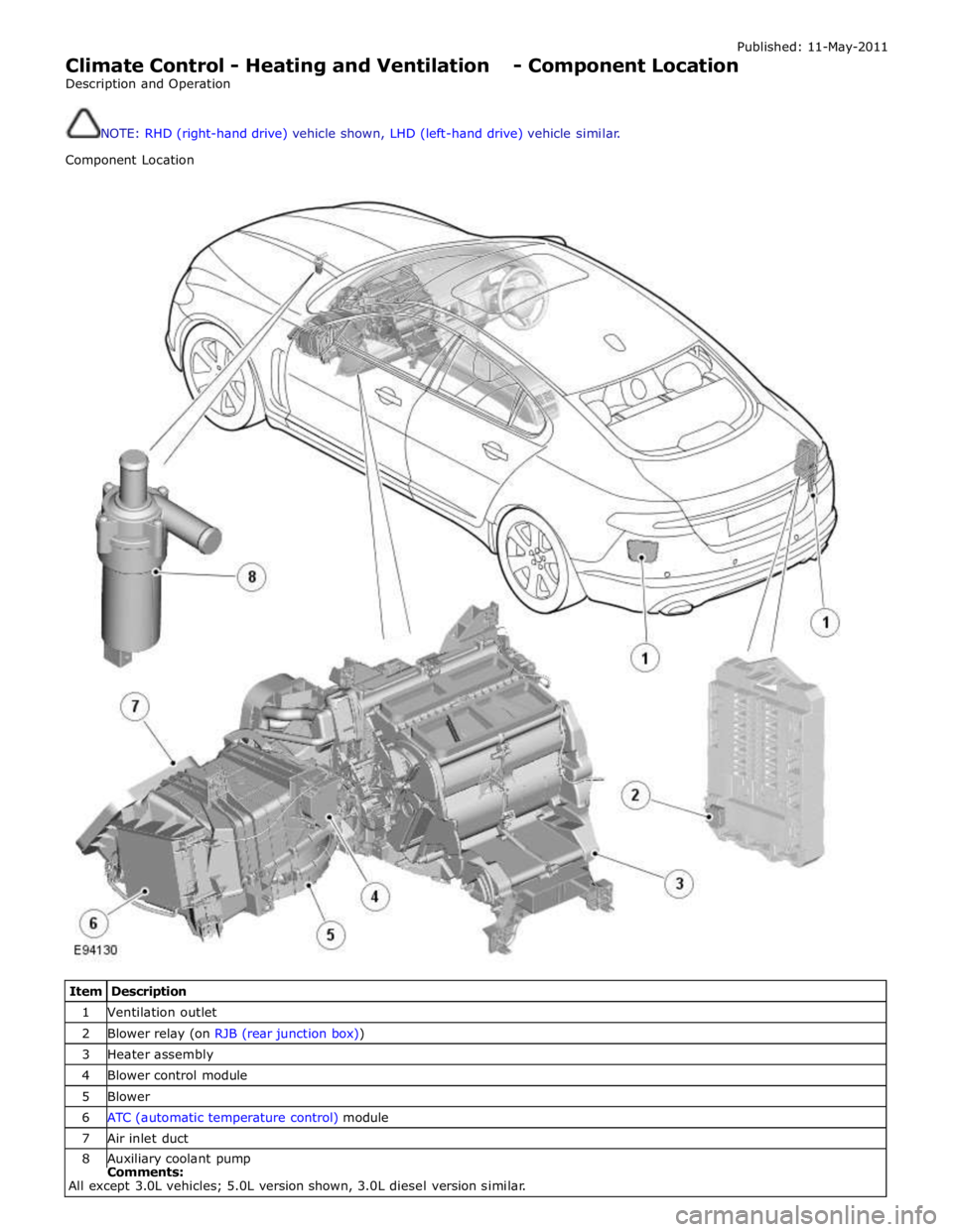
Climate Control - Heating and Ventilation - Component Location
Description and Operation
NOTE: RHD (right-hand drive) vehicle shown, LHD (left-hand drive) vehicle similar.
Component Location
Item Description 1 Ventilation outlet 2 Blower relay (on RJB (rear junction box)) 3 Heater assembly 4 Blower control module 5 Blower 6 ATC (automatic temperature control) module 7 Air inlet duct 8 Auxiliary coolant pump Comments:
All except 3.0L vehicles; 5.0L version shown, 3.0L diesel version similar.
Page 1692 of 3039
Published: 11-May-2011
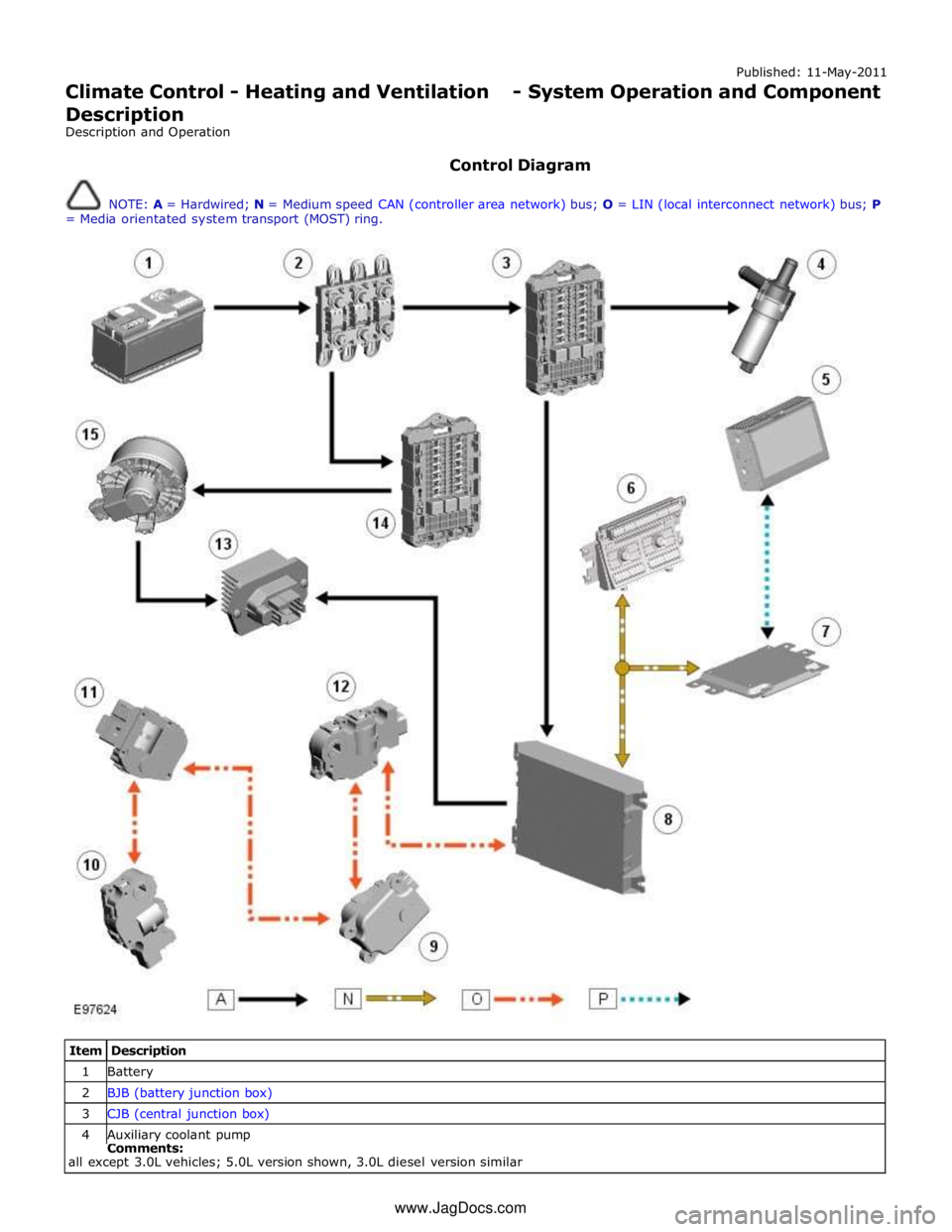
Climate Control - Heating and Ventilation - System Operation and Component Description
Description and Operation
Control Diagram
NOTE: A = Hardwired; N = Medium speed CAN (controller area network) bus; O = LIN (local interconnect network) bus; P
= Media orientated system transport (MOST) ring.
Item Description 1 Battery 2 BJB (battery junction box) 3 CJB (central junction box) 4 Auxiliary coolant pump Comments:
all except 3.0L vehicles; 5.0L version shown, 3.0L diesel version similar www.JagDocs.com
Page 1693 of 3039
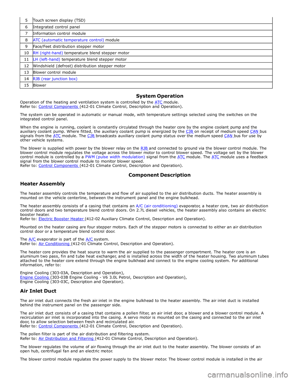
Touch screen display (TSD) 6 Integrated control panel 7 Information control module 8 ATC (automatic temperature control) module 9 Face/Feet distribution stepper motor 10 RH (right-hand) temperature blend stepper motor 11 LH (left-hand) temperature blend stepper motor 12 Windshield (defrost) distribution stepper motor 13 Blower control module 14 RJB (rear junction box) 15 Blower
System Operation
Operation of the heating and ventilation system is controlled by the ATC module. Refer to: Control Components (412-01 Climate Control, Description and Operation).
The system can be operated in automatic or manual mode, with temperature settings selected using the switches on the
integrated control panel.
When the engine is running, coolant is constantly circulated through the heater core by the engine coolant pump and the
auxiliary coolant pump. Where fitted, the auxiliary coolant pump is energized by the CJB on receipt of medium speed CAN bus signals from the ATC module. The CJB broadcasts auxiliary coolant pump status over the medium speed CAN bus for use by other vehicle systems.
The blower is supplied with power by the blower relay on the RJB and connected to ground via the blower control module. The blower control module regulates the voltage across the blower motor to control blower speed. The voltage set by the blower
control module is controlled by a PWM (pulse width modulation) signal from the ATC module. The ATC module uses a feedback signal from the blower control module to monitor blower speed.
Refer to: Control Components (412-01 Climate Control, Description and Operation).
Heater Assembly Component Description
The heater assembly controls the temperature and flow of air supplied to the air distribution ducts. The heater assembly is
mounted on the vehicle centerline, between the instrument panel and the engine bulkhead.
The heater assembly consists of a casing that contains an A/C (air conditioning) evaporator, a heater core, two air distribution
control doors and two temperature blend control doors. On 2.7L diesel vehicles, the heater assembly also contains an electric
booster heater.
Refer to: Electric Booster Heater (412-02 Auxiliary Climate Control, Description and Operation).
Mounted on the heater casing are four stepper motors. Each of the stepper motors is connected to either an air distribution
control door or a temperature blend control door.
The A/C evaporator is part of the A/C system. Refer to: Air Conditioning (412-01 Climate Control, Description and Operation).
The heater core provides the heat source to warm the air supplied to the passenger compartment. The heater core is an
aluminum two pass, fin and tube heat exchanger, and is installed across the width of the heater housing. Two aluminum tubes
attached to the heater core extend through the engine bulkhead and connect to the engine cooling system. For additional
information, refer to:
Engine Cooling (303-03A, Description and Operation),
Engine Cooling (303-03B Engine Cooling - V6 3.0L Petrol, Description and Operation), Engine Cooling (303-03C, Description and Operation).
Air Inlet Duct
The air inlet duct connects the fresh air inlet in the engine bulkhead to the heater assembly. The air inlet duct is installed
behind the instrument panel on the passenger side.
The air inlet duct consists of a casing that contains a pollen filter, an air inlet door, a blower and a blower control module. A
recirculation air inlet is incorporated into the casing. A servo motor is mounted on the casing and connected to the air inlet
door, to allow selection between fresh and recirculated air.
Refer to: Control Components (412-01 Climate Control, Description and Operation). The pollen filter is part of the air distribution and filtering system.
Refer to: Air Distribution and Filtering (412-01 Climate Control, Description and Operation).
The blower regulates the volume of air flowing through the air inlet duct to the heater assembly. The blower consists of an
open hub, centrifugal fan and an electric motor.
The blower control module regulates the power supply to the blower motor. The blower control module is installed in the air
Page 1708 of 3039
Published: 11-May-2011
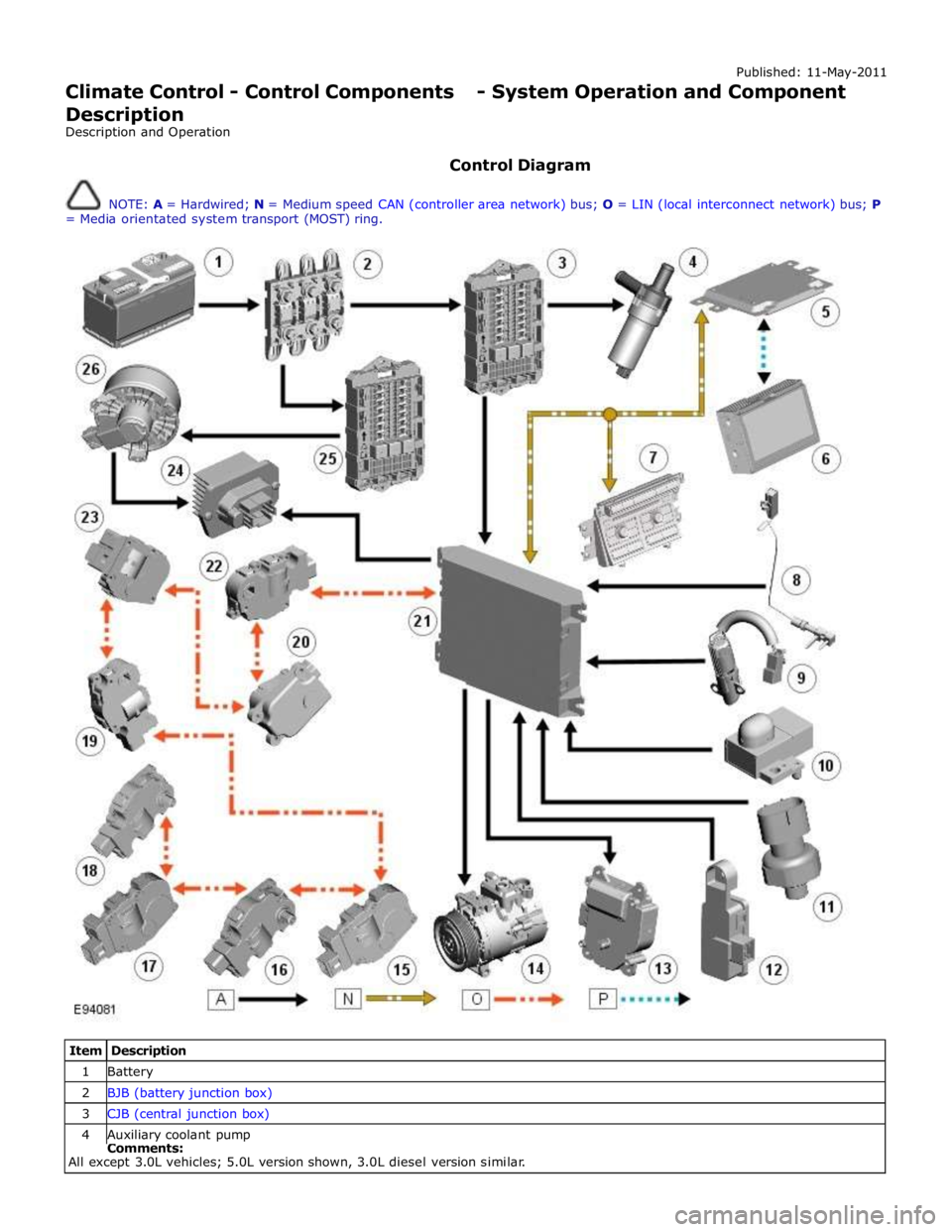
Climate Control - Control Components - System Operation and Component Description
Description and Operation
Control Diagram
NOTE: A = Hardwired; N = Medium speed CAN (controller area network) bus; O = LIN (local interconnect network) bus; P
= Media orientated system transport (MOST) ring.
Item Description 1 Battery 2 BJB (battery junction box) 3 CJB (central junction box) 4 Auxiliary coolant pump Comments:
All except 3.0L vehicles; 5.0L version shown, 3.0L diesel version similar.
Page 1709 of 3039
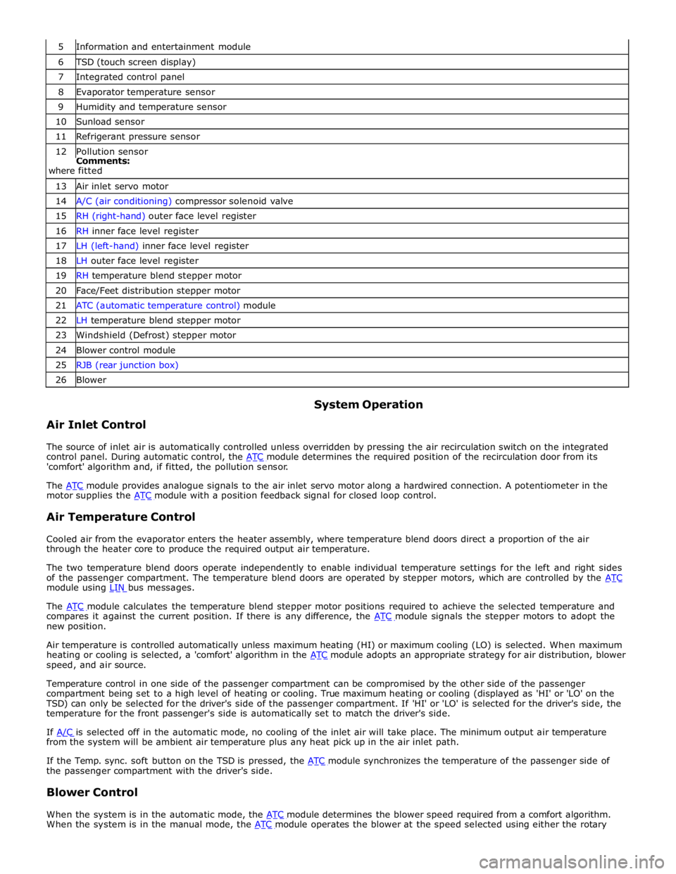
6 TSD (touch screen display) 7 Integrated control panel 8 Evaporator temperature sensor 9 Humidity and temperature sensor 10 Sunload sensor 11 Refrigerant pressure sensor 12 Pollution sensor Comments:
where fitted 13 Air inlet servo motor 14 A/C (air conditioning) compressor solenoid valve 15 RH (right-hand) outer face level register 16 RH inner face level register 17 LH (left-hand) inner face level register 18 LH outer face level register 19 RH temperature blend stepper motor 20 Face/Feet distribution stepper motor 21 ATC (automatic temperature control) module 22 LH temperature blend stepper motor 23 Windshield (Defrost) stepper motor 24 Blower control module 25 RJB (rear junction box) 26 Blower
Air Inlet Control System Operation
The source of inlet air is automatically controlled unless overridden by pressing the air recirculation switch on the integrated
control panel. During automatic control, the ATC module determines the required position of the recirculation door from its 'comfort' algorithm and, if fitted, the pollution sensor.
The ATC module provides analogue signals to the air inlet servo motor along a hardwired connection. A potentiometer in the motor supplies the ATC module with a position feedback signal for closed loop control.
Air Temperature Control
Cooled air from the evaporator enters the heater assembly, where temperature blend doors direct a proportion of the air
through the heater core to produce the required output air temperature.
The two temperature blend doors operate independently to enable individual temperature settings for the left and right sides
of the passenger compartment. The temperature blend doors are operated by stepper motors, which are controlled by the ATC module using LIN bus messages.
The ATC module calculates the temperature blend stepper motor positions required to achieve the selected temperature and compares it against the current position. If there is any difference, the ATC module signals the stepper motors to adopt the new position.
Air temperature is controlled automatically unless maximum heating (HI) or maximum cooling (LO) is selected. When maximum
heating or cooling is selected, a 'comfort' algorithm in the ATC module adopts an appropriate strategy for air distribution, blower speed, and air source.
Temperature control in one side of the passenger compartment can be compromised by the other side of the passenger
compartment being set to a high level of heating or cooling. True maximum heating or cooling (displayed as 'HI' or 'LO' on the
TSD) can only be selected for the driver's side of the passenger compartment. If 'HI' or 'LO' is selected for the driver's side, the
temperature for the front passenger's side is automatically set to match the driver's side.
If A/C is selected off in the automatic mode, no cooling of the inlet air will take place. The minimum output air temperature from the system will be ambient air temperature plus any heat pick up in the air inlet path.
If the Temp. sync. soft button on the TSD is pressed, the ATC module synchronizes the temperature of the passenger side of the passenger compartment with the driver's side.
Blower Control
When the system is in the automatic mode, the ATC module determines the blower speed required from a comfort algorithm. When the system is in the manual mode, the ATC module operates the blower at the speed selected using either the rotary
Page 1711 of 3039
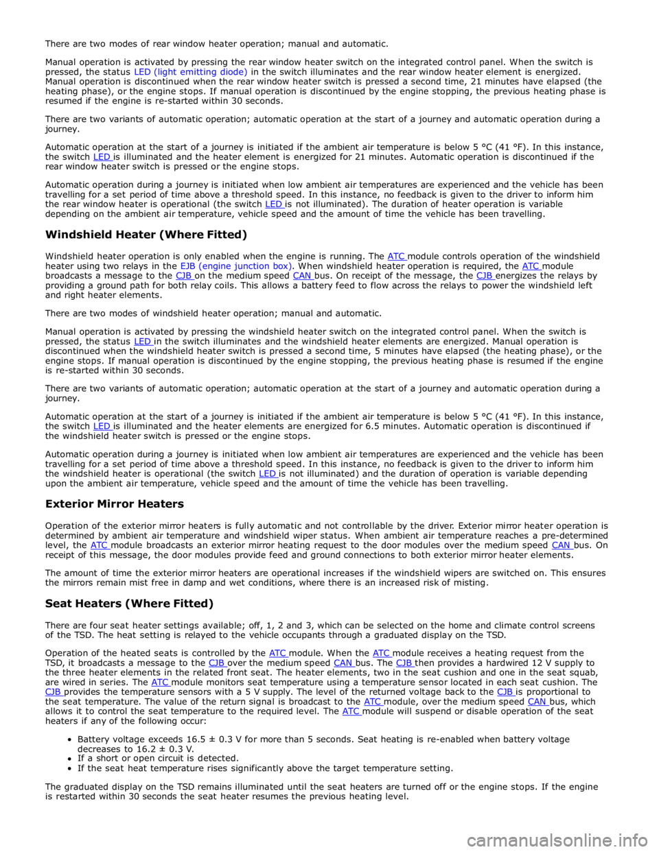
rear window heater switch is pressed or the engine stops.
Automatic operation during a journey is initiated when low ambient air temperatures are experienced and the vehicle has been
travelling for a set period of time above a threshold speed. In this instance, no feedback is given to the driver to inform him
the rear window heater is operational (the switch LED is not illuminated). The duration of heater operation is variable depending on the ambient air temperature, vehicle speed and the amount of time the vehicle has been travelling.
Windshield Heater (Where Fitted)
Windshield heater operation is only enabled when the engine is running. The ATC module controls operation of the windshield heater using two relays in the EJB (engine junction box). When windshield heater operation is required, the ATC module broadcasts a message to the CJB on the medium speed CAN bus. On receipt of the message, the CJB energizes the relays by providing a ground path for both relay coils. This allows a battery feed to flow across the relays to power the windshield left
and right heater elements.
There are two modes of windshield heater operation; manual and automatic.
Manual operation is activated by pressing the windshield heater switch on the integrated control panel. When the switch is
pressed, the status LED in the switch illuminates and the windshield heater elements are energized. Manual operation is discontinued when the windshield heater switch is pressed a second time, 5 minutes have elapsed (the heating phase), or the
engine stops. If manual operation is discontinued by the engine stopping, the previous heating phase is resumed if the engine
is re-started within 30 seconds.
There are two variants of automatic operation; automatic operation at the start of a journey and automatic operation during a
journey.
Automatic operation at the start of a journey is initiated if the ambient air temperature is below 5 °C (41 °F). In this instance,
the switch LED is illuminated and the heater elements are energized for 6.5 minutes. Automatic operation is discontinued if the windshield heater switch is pressed or the engine stops.
Automatic operation during a journey is initiated when low ambient air temperatures are experienced and the vehicle has been
travelling for a set period of time above a threshold speed. In this instance, no feedback is given to the driver to inform him
the windshield heater is operational (the switch LED is not illuminated) and the duration of operation is variable depending upon the ambient air temperature, vehicle speed and the amount of time the vehicle has been travelling.
Exterior Mirror Heaters
Operation of the exterior mirror heaters is fully automatic and not controllable by the driver. Exterior mirror heater operation is
determined by ambient air temperature and windshield wiper status. When ambient air temperature reaches a pre-determined
level, the ATC module broadcasts an exterior mirror heating request to the door modules over the medium speed CAN bus. On receipt of this message, the door modules provide feed and ground connections to both exterior mirror heater elements.
The amount of time the exterior mirror heaters are operational increases if the windshield wipers are switched on. This ensures
the mirrors remain mist free in damp and wet conditions, where there is an increased risk of misting.
Seat Heaters (Where Fitted)
There are four seat heater settings available; off, 1, 2 and 3, which can be selected on the home and climate control screens
of the TSD. The heat setting is relayed to the vehicle occupants through a graduated display on the TSD.
Operation of the heated seats is controlled by the ATC module. When the ATC module receives a heating request from the TSD, it broadcasts a message to the CJB over the medium speed CAN bus. The CJB then provides a hardwired 12 V supply to the three heater elements in the related front seat. The heater elements, two in the seat cushion and one in the seat squab,
are wired in series. The ATC module monitors seat temperature using a temperature sensor located in each seat cushion. The CJB provides the temperature sensors with a 5 V supply. The level of the returned voltage back to the CJB is proportional to the seat temperature. The value of the return signal is broadcast to the ATC module, over the medium speed CAN bus, which allows it to control the seat temperature to the required level. The ATC module will suspend or disable operation of the seat heaters if any of the following occur:
Battery voltage exceeds 16.5 ± 0.3 V for more than 5 seconds. Seat heating is re-enabled when battery voltage
decreases to 16.2 ± 0.3 V.
If a short or open circuit is detected.
If the seat heat temperature rises significantly above the target temperature setting.
The graduated display on the TSD remains illuminated until the seat heaters are turned off or the engine stops. If the engine
is restarted within 30 seconds the seat heater resumes the previous heating level.
Page 1766 of 3039
Published: 11-May-2011
Auxiliary Climate Control - Electric Booster Heater - System Operation and
Component Description
Description and Operation
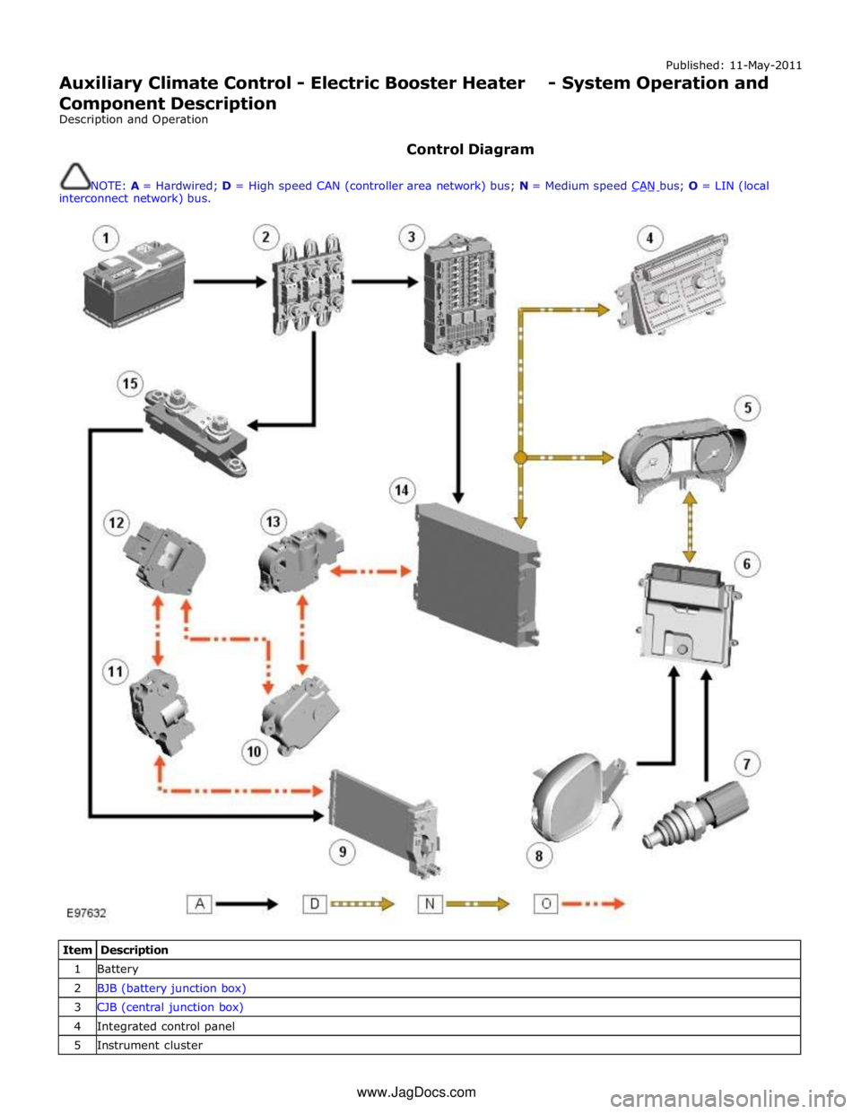
Control Diagram
NOTE: A = Hardwired; D = High speed CAN (controller area network) bus; N = Medium speed CAN bus; O = LIN (local interconnect network) bus.
Item Description 1 Battery 2 BJB (battery junction box) 3 CJB (central junction box) 4 Integrated control panel 5 Instrument cluster www.JagDocs.com
Page 1783 of 3039
Published: 11-May-2011
Instrument Cluster - Instrument Cluster - System Operation and Component Description
Description and Operation
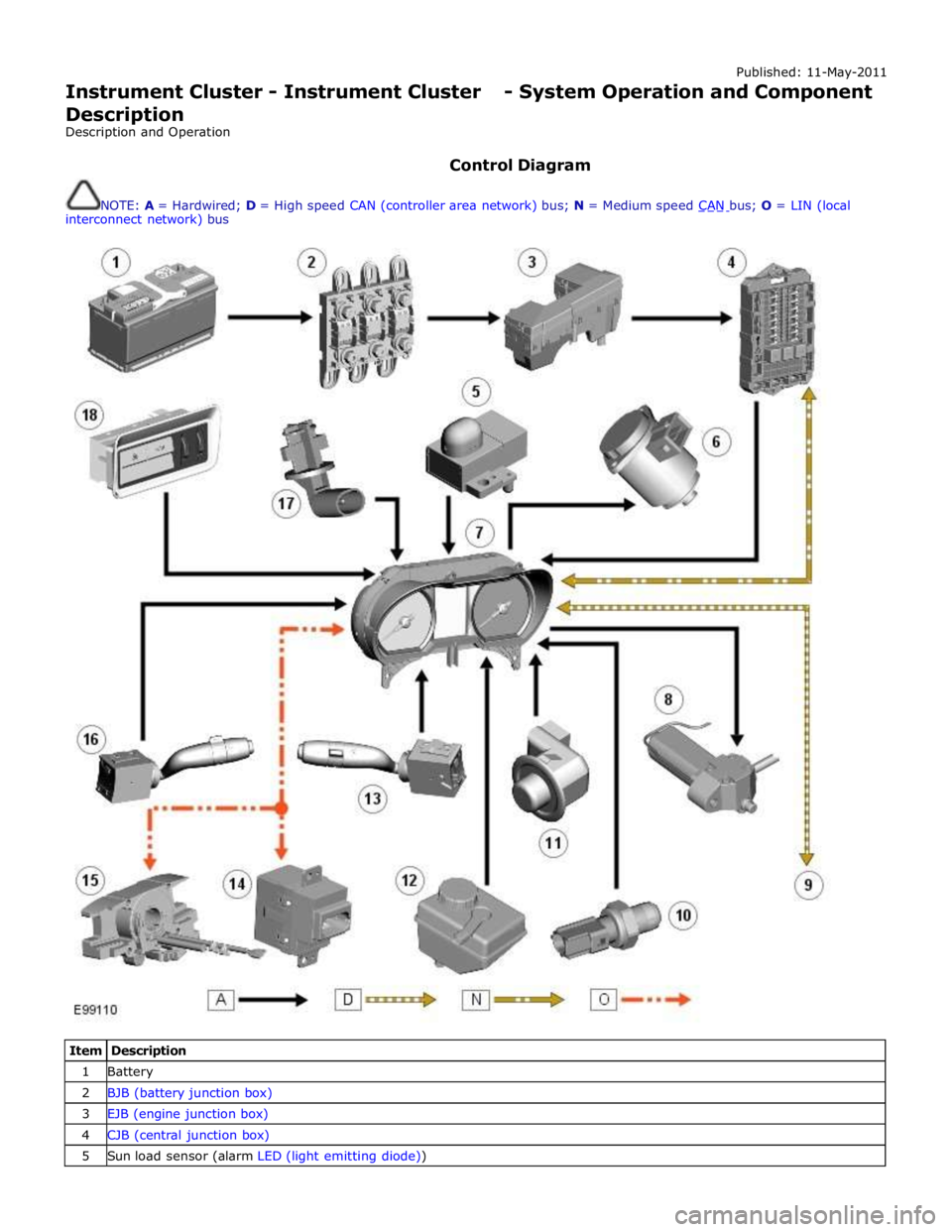
Control Diagram
NOTE: A = Hardwired; D = High speed CAN (controller area network) bus; N = Medium speed CAN bus; O = LIN (local interconnect network) bus
Item Description 1 Battery 2 BJB (battery junction box) 3 EJB (engine junction box) 4 CJB (central junction box) 5 Sun load sensor (alarm LED (light emitting diode))
Page 1785 of 3039
The functionality for each of the above warning indicators is described in the following sections:
1 and 2. Turn Signal Indicators
The turn signal indicators are controlled by the CJB on receipt of medium speed CAN bus signals from the instrument cluster.
The instrument cluster outputs a voltage to the turn signal indicator switch. The switch contains resistors of different values.
When the switch is operated in either the LH or RH direction, the voltage is passed to a ground connection in the instrument cluster which detects the reduced voltage supplied via the resistors. When the turn signal indicator switch is operated in the
LH or RH direction, the instrument cluster detects the ground voltage and determines whether a LH or RH selection is made.
The instrument cluster transmits a medium speed CAN message to the CJB for operation of the applicable turn signal indicators. The message can contain a number of states for each possible switch position and also an out of range low and
high state for circuit faults and an initial value for the switch neutral position. The turn signal indicators are not subject to the
3 second indicator check when the ignition is switched on.
The RJB (rear junction box) software controls the flash rate of the warning indicator which sends 'ON' and 'OFF' signals to the
instrument cluster which flashes the indicators in a green color. During normal operation, the warning indicator flashes slowly,
accompanied simultaneously by a sound from the instrument cluster sounder. If a fault exists, the RJB transmits a message to the instrument cluster which responds by displaying an appropriate message in the message center.
The hazard warning indicators are controlled by the CJB on receipt of a completed ground path from the hazard warning indicator switch. The CJB outputs a medium speed CAN message to the instrument cluster which operates both the LH and RH turn signal indicators simultaneously. The hazard warning indicators can operate with the ignition switched off, therefore the
CAN message from the CJB will also carry a 'wake-up' message for the instrument cluster. 3. Brake Warning Indicator
This warning indicator is displayed in a red or amber color (dependant on market) as a brake symbol in all markets except
United States of America (USA) which have the word 'BRAKE' in place of the symbol. The indicator is controlled by high speed
CAN messages from the ABS module and the parking brake control module. The indicator is illuminated in a red color for a 3 second indicator check when the ignition is switched on.
The instrument cluster monitors the fluid level in the brake fluid reservoir using a hardwired level switch. If the fluid level falls
to below a determined level, the switch contact is broken and the ABS module detects the low fluid level condition. The instrument cluster illuminates the warning indicator and simultaneously displays a 'BRAKE FLUID LOW' message in the
message center.
NOTE: If both the brake warning indicator and the ABS warning indicator illuminate simultaneously, a major fault in the brake system will have occurred.
The warning indicator also displays parking brake status. When the parking brake is applied, the warning indicator will be
illuminated by the instrument cluster and, if the vehicle is moving, the message 'PARK BRAKE APPLIED' will be also displayed
in the message center in response to a CAN message from the parking brake control module.
If a condition exists where the parking brake cannot be applied, the parking brake control module issues a CAN message to the instrument cluster which flashes the warning lamp on and off and is accompanied with a message 'CANNOT APPLY PARK BRAKE'.
If a fault occurs in the parking brake system, the parking brake control module issues a CAN message to the instrument cluster which illuminates the warning indicator and displays the message 'PARK BRAKE FAULT' in the message
center.
4. Forward Alert Indicator
The forward alert system uses the components of the adaptive speed control system to alert the driver of the presence of a
vehicle ahead. The system can be turned on and off using a switch located in the auxiliary lighting switch when the adaptive
speed control system is off. The indicator is illuminated in an amber color for a 3 second indicator check when the ignition is
switched on.
The forward alert system is controlled by the adaptive speed control module. When the switch is pressed, the forward alert
system is activated and the adaptive speed control module issues a forward alert active message on the high speed CAN bus to the instrument cluster. The forward alert icon in the instrument cluster will illuminate in an amber color and a 'FORWARD
ALERT' message will be displayed in the message center. When the button is pressed a second time, the module issues a
forward alert off CAN message. The forward alert system will be deactivated, the forward alert icon will go off and a message 'FORWARD ALERT OFF' will be displayed in the message center.
5. Automatic Speed Limiter (ASL) Indicator
The ASL is controlled by the ECM (engine control module). An ASL switch is located in the floor console, adjacent to the gear
selector lever. When the ASL switch is pressed, this is sensed by the ECM which issues a high speed CAN message to the instrument cluster. The instrument cluster illuminates the ASL warning indicator in an amber color to show the driver that ASL
is active. The driver sets the required speed using the speed control SET +/- switches on the steering wheel. The selected
speed is shown by the message ' LIMITER SET XXX MPH / K/MH' in the message center. The indicator is illuminated in an
amber color for a 3 second indicator check when the ignition is switched on. ASL can be deselected by pressing the ASL switch,
by depressing the throttle pedal initiating kick-down or by pressing the 'cancel' switch on the steering wheel. The ASL indicator
will go off and the message center will display the message 'limiter cancelled' for 4 seconds. If a fault occurs in the ASL
system, the ECM will send a message to the instrument cluster to illuminate the ASL indicator and display the message 'LIMITER NOT AVAILABLE'.
Page 1787 of 3039
the RCM and illuminated by the instrument cluster on receipt of high speed CAN bus messages. The safety belt warning indicator is not subject to the 3 second indicator check when the ignition is switched on.
The operation of the passenger seat buckle switch is as described below with the exception that the instrument cluster must
receive a hardwired signal from the belt minder control module to indicate that a passenger is occupying the seat.
The safety belt warning indicator is subject to a timer. The warning indicator is activated when the following conditions exist:
Ignition is switched on
One of the front seat belts is unbuckled
USA market only - 75 seconds has elapsed after ignition on mode is selected
Vehicle is not in reverse gear
Vehicle speed is more than 8 km/h (5 mph).
Once the above parameters are met, the instrument cluster flashes the warning indicator at 2 Hz for 10 seconds accompanied
by a simultaneous chime. After 10 seconds the chime ceases and the warning indicator is permanently illuminated for 20
seconds. This sequence is repeated every 30 seconds until one of the following events occurs:
300 seconds has elapsed
The safety belt of the occupied front seats is fastened
The ignition is switched to off mode
The vehicle speed decreases to below 5 km/h (3 mph).
NOTE: On USA market vehicles, the warning indicator in not permanently illuminated.
The safety belt minder function cannot be disabled. The seat belt minder function can be disabled.
Refer to: Safety Belt System (501-20A Safety Belt System, Description and Operation). 14. Side Lamp Indicator
The instrument cluster controls the green colored side lamp indicator on receipt of a side lamp status message on the medium
speed CAN bus from the CJB and the auxiliary junction box. The lighting switch on the LH steering column multifunction switch is connected to the instrument cluster. Selections using this switch are detected by the cluster which requests the side or
headlamp operation via a message to the CJB and the RJB. The CJB and the RJB responds with a side lamp active message and the cluster illuminates the side lamp indicator. The side lamp indicator is not subject to the 3 second indicator check when
the ignition is switched on.
15. High Beam Indicator
The instrument cluster controls the blue colored high beam indicator on receipt of a high beam status message on the medium
speed CAN bus from the CJB. The lighting switch on the LH steering column multifunction switch is connected to the instrument cluster. High beam or flash selections using this switch are detected by the cluster which requests the light
operation via a CAN message to the CJB. The CJB responds with a high beam active message and the cluster illuminates the high beam indicator. The high beam indicator is not subject to the 3 second indicator check when the ignition is switched on.
16. Rear Fog Lamp Indicator
The amber colored rear fog lamp indicator is controlled by the auxiliary junction box and illuminated by the instrument cluster
on receipt of a rear fog lamp on message on the medium speed CAN bus from the RJB. The indicator is illuminated for as long as the rear fog lamps are active. The rear fog lamp indicator is not subject to the 3 second indicator check when the ignition is
switched on.
SPEEDOMETER
The speedometer is driven by high speed CAN signals transmitted by the ABS module. The wheel speeds are measured by sensors reading the rotational speed of the rear wheels from toothed targets on the hubs. An average of the two wheel speeds
are passed from the sensors to the ABS module in the form of pulsed signals. The ABS module converts these signals into a speed output on the high speed CAN to the instrument cluster. The same speed outputs from the wheel speed sensors are also used to calculate the distance the vehicle has travelled.
TACHOMETER
The tachometer is driven by an engine speed signal transmitted on the high speed CAN from the ECM. The signal is derived from the CKP (crankshaft position) sensor. The signal is received by the instrument cluster microprocessor and the output from
the microprocessor drives the tachometer.
FUEL GAGE
The fuel gage is controlled by CAN messages from the RJB. The RJB reads the values output by the fuel level sensors every 131 ms and transmits a fuel tank contents value, corrected for battery voltage, in a CAN message to the instrument cluster. A fuel pump symbol is displayed to the left of the linear gage. An arrow above the symbol shows the driver on which side of the
vehicle the fuel filler cap is located. Above the linear fuel gage, is a LCD (liquid crystal display) area which displays odometer
and trip readouts. When a trip computer function is selected, these are replaced by a trip computer display for the trip function
selected.
LIQUID CRYSTAL DISPLAY
In the area above and below the message center is a LCD display. The area below the message center displays a linear fuel www.JagDocs.com